SEE QUICK SET UP GUIDE ON REAR SIDE CONTENTS VIDEO CASSETTE RECORDER HR-DD845EK SAFETY FIRST 2 Safety Precautions ...................... 2 Some Do's And Don'ts ............... 3 INSTALLING YOUR NEW RECORDER 4 Basic Connections ..................... 4 INITIAL SETTINGS 6 Video Channel Set ..................... 6 Auto Set Up ............................... 8 Video Plus+ Setup .................... 10 PLAYBACK 12 Basic Playback ......................... 12 Playback Features ....................
SAFETY FIRST Safety Precautions The rating plate and the safety caution are on the rear of the unit. WARNING: DANGEROUS VOLTAGE INSIDE WARNING: TO PREVENT FIRE OR SHOCK HAZARD, DO NOT EXPOSE THIS UNIT TO RAIN OR MOISTURE. IMPORTANT IMPORTANT Connection to the mains supply in the United Kingdom. DO NOT cut off the mains plug from this equipment.
Some Do's And Don'ts On The Safe Use Of Equipment This equipment has been designed and manufactured to meet international safety standards but, like any electrical equipment, care must be taken if you are to obtain the best results and safety is to be assured. DO read the operating instructions before you attempt to use the equipment.
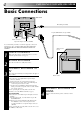
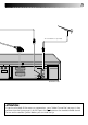
INSTALLING YOUR NEW RECORDER Basic Connections Back of TV RF Cable (provided) 21-pin SCART Cable (not provided) Aerial connector 21-pin AV input connector (SCART) It's essential that your video recorder be properly connected. Follow these steps carefully. THESE STEPS MUST BE COMPLETED BEFORE ANY VIDEO OPERATION CAN BE PERFORMED. 1 2 3 Mains Power Cord CHECK CONTENTS Make sure the package contains all of the accessories listed in “Specifications” (Z pg. 53).
TV Aerial Cable (not provided) ANT. IN R AUDIO L OUT AV1 IN / OUT AV2 IN PAUSE RF OUT Back of Recorder ATTENTION If you have finished all the necessary connections, go to "Video Channel Set" on page 6, then button on the recorder/remote control perform Auto Set Up on page 8; do NOT press the to turn on the recorder's power before you start Auto Set Up.
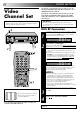
INITIAL SETTINGS If you have connected the video recorder to your TV via the provided RF cable only (RF connection) – Go to "With RF Connection" below. Video Channel Set If you have connected the video recorder to your TV via both the provided RF cable and a 21-pin SCART cable (AV connection) – Go to "With AV Connection" on next page. Video Channel (RF Output Channel) is the channel on which your TV receives picture and sound signals from the video recorder through the RF cable.
4 IMPORTANT: Before performing the following steps, make sure the recorder's power is off and there is no cassette inserted in the recorder. With AV Connection 2 STOP TV PROG+/– q 1 4 2 1 2 3 4 5 6 7 8 9 0 2 4 3 Press and hold down STOP on the recorder until the display panel shows the following. SET VIDEO CHANNEL Press TV PROG – until the display panel shows "–OUT– –". ● Now the video channel is set to off.
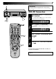
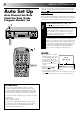
INITIAL SETTINGS (cont.) The Auto Set Up function sets the tuner channels, clock and Video Plus+ assigned Guide Program numbers automatically when the button on the recorder/remote is first pressed to power on the recorder after you plug the mains power cord into a mains outlet.
Auto Set Up results appear on the display panel ● When both auto channel set and auto clock set have been completed successfully the correct current time will be displayed. ● When auto channel set has been completed successfully but auto clock set has not, "CH" will be displayed. ● When neither auto channel set nor auto clock set has been completed successfully, "--:--" will be displayed. * See "Video Plus+ Setup" on page 10 to check if the Guide Program numbers have been set correctly.
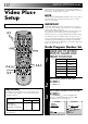
INITIAL SETTINGS (cont.) Video Plus+ Setup With Video Plus+, timer programming is greatly simplified because each TV programme has a corresponding code number which your recorder is able to recognise. NOTE: “Guide Program (GUIDE PROG) number" refers to the assigned TV station numbers, according to broadcast area, for Video Plus+ timer recording. Turn on the TV and select the VIDEO channel (or AV mode).
4 5 4 ENTER PLUSCODE NUMBER Press OK, and a cursor GUIDE PROG SET appears above “GUIDE 12345 PROG”. Then, using the NUMBER keys, input the GUIDE PROG TV PROG 1 1 PlusCode number (found in most TV listings) of a program scheduled to be broadcast on each station [0-9] = [MENU] : EXIT on the list from step 1, starting at the top. If you enter the wrong number, press CANCEL to backspace and input the correct number.
PLAYBACK The easiest, most basic operation possible with your video recorder is tape playback. Already-recorded signals on a video tape are read by your video recorder and displayed on your TV just like a TV programme. Basic Playback Turn on the TV and select the VIDEO channel (or AV mode). 1 LOAD A CASSETTE Make sure the window side is up, the rear label side is facing you and the arrow on the front of the cassette is point toward the recorder. Don’t apply too much pressure when inserting.
Take advantage of special functions possible with the recorder’s controls or the remote control. Playback Features Still Picture/Frame-By-Frame Playback N CA ES M TI 1 LE JO TT G U SH 7 PLAY PAUSE TV PROG q 9 8 0 2 PAUSE DURING PLAYBACK Press PAUSE. If there is vertical jitter, use the TV PROG buttons to correct the picture. ● During still picture, the sound from the previous 3 seconds (approx.
PLAYBACK (cont.) Your video recorder is equipped with automatic tracking control. During playback, you can override this and adjust the tracking manually by pressing the TV PROG buttons. 3R PI CT U RE COUNTER RESET Manual Tracking 1 C. M EM O RY STOP TV PROG q REVIEW 2 2 1 2 3 4 5 6 7 8 9 0 C.RESET 4 TV PROG 3 OVERRIDE AUTOMATIC TRACKING Press on the remote to engage manual tracking. ADJUST TRACKING MANUALLY Press TV PROG + or – to adjust tracking.
3R Picture Instant ReView 3R(= Resolution and Response Recovery technology) maximises sense of resolution and sharpens image edges to make playback picture look better focused. Simply by pressing a single button, the recorder power comes on, rewinds, and begins playback of the last timer-recorded programme. If you have several programmes recorded, you can easily access any of them. 1 ACTIVATE 3R PICTURE NOTE: Press 3R PICTURE. The button will light.
PLAYBACK (cont.) SpatializerW SPATIALIZER This feature expands sound field when you play back any stereo source or view a stereo programme while recording it. *SpatializerW has no effect on recording quality. 1 PLAY O ST C. M RY O EM 2 1 2 3 4 5 6 7 8 9 0 Press SPATIALIZER; the current setting will be displayed on the screen for about 5 seconds. Pressing SPATIALIZER while the screen shows the display changes the setting.
Scene Finder Repeat Playback This function helps you check contents of unlabeled recorded tapes at the touch of a single button. Your video recorder can automatically play back the whole tape 20 times repeatedly. Search Search FF REW FF 5 seconds 10 minutes on counter Search REW FF 5 seconds 10 minutes on counter REW 5 seconds NOTE: Scene Finder cannot be used when the recorder is in the Record mode. 1 ACTIVATE SCENE FINDER Press SCENE FINDER.
PLAYBACK (cont.) TIME SCAN SHUTTLE TimeScan PLAY q Your recorder is equipped with the TimeScan function. TimeScan allows noise free pictures to be displayed on your TV screen in the forward and reverse search modes. Audio will be played back at normal speed during any of the TimeScan modes (Z pg. 19). TimeScan allows you to view a program in search mode while listening to the audio. The default setting for TimeScan audio is ON. (Z pg.
TimeScan Reverse Names of special-effects playback Speed SP Forward Search Play Slow-Motion *Still -9x -7x -5x -3x -1x -1/6x -1/18x 0 1/18x -1/6x -1/18x 0 1/18x Audio is not output. Audio is output. Speed LP -7x Audio output -3x Audio is output. Slow-Motion Play Search 1/6x 1x 2x 3x 5x 7x 9x 1/6x 1x 2x Audio is not output. 5x 9x Audio is output. * Still mode cannot be engaged using the remote control's PUSH JOG button.
RECORDING TV signals being received by the recorder’s built-in tuner can be recorded onto a video tape. You can “capture” a TV programme using your video recorder. Basic Recording 1 TV PROG Turn on the TV and select the VIDEO channel (or AV mode).
Record One Programme While Watching Another Recording Features COUNTER RESET 1 2 C.RESET 2 3 4 5 6 7 8 9 0 1 2 SET COUNTER DISPLAY Press DISPLAY until a counter reading appears on the dispay panel. RESET COUNTER Press C. (COUNTER) RESET before starting recording or playback. ● The counter is reset to “0:00:00” and shows the exact elapsed time as the tape runs.
RECORDING (cont.) B.E.S.T. Picture System Turn on the TV and select the VIDEO channel (or AV mode). Recording 1 2 RE CO RD q The B.E.S.T. (Biconditional Equalised Signal Tracking) system checks the condition of the tape in use during recording and playback, and compensates to provide the highest-possible recording and playback pictures. The default setting for both recording and playback is “ON”. 3 2 1 2 3 4 5 6 7 8 9 0 Insert a cassette with the record safety tab intact.
NOTES: RE ● The B.E.S.T. system works for both SP and LP modes only after a tape has been inserted and the Record mode is first initiated. It does not work during recording. ● In the case of timer recording, the B.E.S.T. system works before recording is initiated. ● Once the cassette is ejected, the B.E.S.T. data is cancelled. The next time the cassette is used for recording, B.E.S.T. is reperformed. CO RD 2 1 2 3 4 5 6 7 8 9 0 PLAY PAUSE q ATTENTION: Since the B.E.S.T.
TIMER RECORDING Video Plus+ Timer Recording 1 : PDC 3 4 5 6 7 8 9 0 CANCEL ENTER PLUSCODE NUMBER Press the NUMBER keys to enter the PlusCode number of a programme you wish to record. ● If you make a mistake, press CANCEL to backspace and then input the correct number.
6 TIMER 4 5 6 q ADD TIME 1 2 4 5 3 LY I DA 6 7 8 9 WEEKLY 4 TIMER 6 RETURN TO NORMAL SCREEN Press OK. ● Repeat steps 1 – 5 for each additional programme. ENGAGE RECORDER’S TIMER MODE Press TIMER. The recorder turns off automatically. To Timer-Record Weekly Or Daily Serials . . . . . . after pressing OK in step 3, press WEEKLY (NUMBER key “9”) for weekly serials or DAILY (NUMBER key “8”) for daily serials (Monday – Friday). Either "WEEKLY" or "DAILY" appears on the screen.
TIMER RECORDING(cont.) Regular Timer Programming Remember, the clock must be set before you can progamme the timer (Z pg. 48). Before performing the following steps: ● Insert a cassette with the safety tab in place. The recorder will come on automatically. ● Turn on the TV and select the VIDEO channel (or AV mode). If you don’t know the PlusCode number for the programme you wish to record, use the following procedure to set your recorder to timer-record the programme.
9 TIMER 6 ENTER PRESET POSITION Press TV PROG +/–. – P1 – START 21:00 = STOP 22:00 SP DATE 25.12 q [+/–] = [MENU] : EXIT OFF TV PROG 1 BBC 1 SP IMPORTANT : PDC LY 2 2 3 4 5 6 7 8 9 D AI 1 0 7 Be sure to confirm the setting of PDC recording. ● If " ON" is displayed on the screen or " " is lit on the display panel, PDC is set to ON. ● If " OFF" is displayed on the screen or " " is not lit on the display panel, PDC is set to OFF.
TIMER RECORDING(cont.) TIMER Check And Cancel Programmes 1 AU TO SP /L P TI M ER q 2 1 2 3 4 5 6 7 8 9 0 CANCEL TIMER 4 TV PROG START+/– REVISE PROGRAMME INFORMATION Input the appropriate data using the START +/–, STOP +/–, DATE +/– and TV PROG +/– buttons on the remote control. STOP+/– /– PUSH JOG ● The display panel shows the programme start time. Pressing OK changes the display to the programme stop time, then the date and preset position.
Auto Timer Auto SP/LP Timer When the Auto Timer is set to ON the timer is automatically engaged when the recorder power is turned off and automatically disengaged when the recorder is powered back on. If, when recording in SP mode, there is not enough tape to record the entire programme, the recorder automatically switches to LP mode to allow complete recording. 1 2 ACCESS MAIN MENU SCREEN Press MENU twice.
EDITING You can use your video recorder as the source player or the recording deck. Edit To Or From Another 1 Video Recorder . 2 2 1 2 3 4 5 6 7 8 9 0 NUMBER "0" 4 TV PROG 3 4 MAKE CONNECTIONS Connect the player’s 21-pin SCART connector to the recorder’s 21-pin SCART connector as illustrated on the below. When Using Your Video Recorder As The Source Player . . . . . . connect its AV1 IN/OUT connector to the recording deck. When Using Your Video Recorder As The Recording Deck . . . . .
Edit From A Camcorder You can use a camcorder as the source player and your video recorder as the recorder. MAKE CONNECTIONS 1 Connect the camcorder’s AUDIO/VIDEO OUT connectors to the recorder’s front panel AUDIO/VIDEO input connectors. ● When using a monaural camcorder, connect its AUDIO OUT connector to the AUDIO L input connector on your recorder. ● When a Master Edit Control-equipped JVC camcorder is used, the camcorder is capable of controlling the recorder.
EDITING (cont.) STOP TV PROG Audio Dubbing Audio dubbing replaces the normal audio sound of a previously recorded tape with a new soundtrack. Normal audio track Video/Hi-Fi audio track Audio-dubbed tape PLAY A. PAUSE D U B q 1 2 3 4 CD Player CD Player Mixer output Pre-recorded tape Audio mixer Original sound AUDIO OUT q 5 MAKE CONNECTIONS Connect an audio component to the AUDIO IN L + R connectors on the recorder's front panel.
SYSTEM CONNECTIONS Connection To A Stereo System These instructions enable you to connect your video recorder to your Hi-Fi stereo system (if you have one) and listen to the soundtrack through the stereo. FM Tuner CD Player Stereo Amplifier AUX IN or TAPE MONITOR I I I I I I I I I I I I I I I I I I I I I I I I I I I I I I I I I I I I I I I I I I I Audio Cable (not provided) Mains outlet Speaker Television Speaker ANT.
SYSTEM CONNECTIONS (cont.) The AV2 IN connector on the rear panel of your recorder allows simple connection to a satellite receiver. Connection To A Satellite Receiver Aerial Outdoor Unit Satellite Cable TV Aerial cable Satellite Receiver Unit ANT.
Aerial connector Back of TV 21-pin AV input connectors (SCART) EXT.2 ANT. IN PAUSE RF OUT EXT.
SPECIAL FEATURES Turn on the TV and select the VIDEO channel (or AV mode). On-Screen Dispiay You can choose whether or not to have various operational indicators appear on screen, by setting this function ON or OFF. A/B CODE 1 2 IO D AU 1 2 3 4 5 6 7 8 9 0 2 4 M O IT N R O FF REW 3 OK 3 MENU 1 PUSH JOG 4 TURN ON THE RECORDER Press . ACCESS MAIN MENU SCREEN Press MENU twice.
Tape Position Indicator The tape position indicator appears on screen when, from the Stop mode, you press FF, REW or perform an Index Search. The position of “5” in relation to “0” (beginning) or “+” (end) shows you where you are on the tape. ”O.S.D.” (Z pg. 36) must be set to “ON”, or the indicator will not appear. Receiving NICAM Stereo And Bilingual Programmes Your recorder is equipped with a Digital stereo sound decoder (NICAM), making reception of stereo and bilingual broadcasts possible.
SPECIAL FEATURES (cont.) TV Multi-brand Remote Control M U N Your remote control can operate the basic functions of your TV set. In addition to JVC TVs, other manufacturer’s TVs can also be controlled by setting the appropriate switch on the remote control. Before you start . . . ● Turn on the TV using its remote control. ● Set the remote control’s TV/SAT/VCR switch to TV. BE 2 R 4 5 6 7 8 9 0 AY 3 PL 2 IS D 1 4 TV PROG 1 TV/SAT/VCR TV R C /V 3 1 Refer to the chart below.
Satellite Receiver MultiBrand Remote Control M U N Your remote control can operate the basic functions of your satellite receiver set. In addition to JVC satellite receivers, other manufacturer’s satellite receivers can also be controlled by setting the appropriate switch on the remote control. Before you start . . . ● Turn on the satellite receiver using its remote control.
TUNER SET Auto Channel Set Turn on the TV and select the VIDEO channel (or AV mode). IMPORTANT Perform the following steps only if auto channel set has not been set correctly by Auto Set Up function (Z pg. 8) or if you have moved to a different area or if a new station starts broadcasting in your area. Your recorder needs to memorise all necessary stations in preset positions in order to record TV programmes. Auto Channel Set automatically assigns all receivable stations in your area.
4 4 5 6 7 8 9 0 % 3 5 2 % 1 The stations your recorder PR CH ID PR CH ID located appear on a 01 26 BBC1 08 –––– 02 33 BBC2 09 –––– Confirmation screen — 03 23 ITV 10 –––– preset positions (PR), 04 30 CH4 11 –––– 05 37 CH5 12 –––– channels (CH) and station 06 –––– 13 –––– names (ID – Z pg. 46). To 07 –––– 14 –––– view the next page of the ] [5∞ = : EDIT listing, press PUSH JOG = [CANCEL] : DELETE %fi .
TUNER SET (cont.) 4 5 6 7 8 9 0 4 Press MENU twice. ACCESS CONFIRMATION SCREEN Press PUSH JOG%fi to move the highlight bar (pointer) to “MANUAL CH SET”, then press OK. The Confirmation screen appears. SELECT POSITION Press PUSH JOG% fi until an open position in which you want to store a channel begins blinking, then press OK. The Manual Ch. Set screen appears. % 3 ACCESS MAIN MENU INPUT CHANNEL The number "21" appears blinking to the right of "CH".
Perform steps 1 and 2 of "Storing Channels Manually" on page 42 to access the Confirmation screen before continuing. Delete A Channel 3 4 5 6 7 8 9 0 CANCEL 4 3 MENU 1 1 2 OK 3 SELECT ITEM Press PUSH JOG%fi delete begins blinking. until the item you want to % 2 % 2 1 DELETE CHANNEL Press CANCEL. ● The item directly beneath the cancelled one moves up one line. ● Repeat steps 1 and 2 as necessary. CLOSE CONFIRMATION SCREEN Press MENU.
TUNER SET (cont.) Perform steps 1 and 2 of "Storing Channels Manually" on page 42 to access the Confirmation screen before continuing. Set Stations (A) 4 5 6 7 8 9 0 1 2 4 3 PUSH JOG 1 OK 4 Press PUSH JOG%fi until the item you want begins blinking. Then press OK twice and the station’s name (ID) begins blinking. SELECT NEW STATION Press PUSH JOG%fi until the new station’s name (ID) you want to store begins blinking. Registered station names (Z pg. 46) appear as you press PUSH JOG%fi.
Perform steps 1 and 2 of "Storing Channels Manually" on page 42 to access the Confirmation screen before continuing. Fine-Tuning Channels Already Stored 3 4 5 6 7 8 9 0 3 MENU PUSH JOG 1 1 4 OK 2 3 4 SELECT CHANNEL TO FINE-TUNE Press PUSH JOG%fi tune begins blinking. % 2 % 2 1 until the channel you want to ACCESS MANUAL CH. SET SCREEN Press OK three times. The Manual Ch. Set screen appears. PERFORM TUNING Press PUSH JOG%fi until the picture is its clearest. Then press OK.
TUNER SET (cont.
TV Station Channel Number Guide Only the main stations are listed. There are in addition many relay stations, and full lists are available from BBC and ITC. BBC1 BBC2 ITV CH4 London & South-East Bluebell Hill .............................. Crystal Palace ............................ Dover ........................................ Heathfield ................................. Oxford ......................................
CLOCK SET IMPORTANT Clock Set Perform the following steps only if Auto Clock Set has not been performed correctly by Auto Set Up ( Z pg. 8) or Auto Channel Set (Z pg. 40) or if the recorder's memory backup has expired. Turn on the TV and select the VIDEO channel (or AV mode). 2 1 2 3 4 5 6 7 8 9 0 If you performed Auto Set Up or Auto Channel Set without ever having set the clock previously, the recorder’s built-in clock is also set automatically.
Auto Clock Set 2 3 4 5 6 7 8 9 0 1 AUTO CLOCK PLEASE WAIT JUST CLOCK: ON TV PR. : 1 ● If "TV PR." isn't set to the preset position on which Auto Clock Set data is received, "ERROR" appears, and then the screen from step 3 reappears. To set "TV PR.", press OK to place the cursor next to it, then cycle through the numbers by pressing PUSH JOG%fi until the number representing the position in which the station transmitting clock setting data (BBC1, BBC2, etc.) is stored appears.
TROUBLESHOOTING Before requesting service for a problem, use this chart and see if you can repair the trouble yourself. Small problems are often easily corrected, and this can save you the trouble of sending your video recorder off for repair. POWER SYMPTOM POSSIBLE CAUSE CORRECTIVE ACTION 1. No power is applied to the recorder. ● The mains power cord is disconnected. Connect the mains power cord. 2. The clock is functioning properly, but the recorder cannot be powered.
4. Camcorder recording is not possible. ● The camcorder has not been properly connected. ● The input mode is not correct. Confirm that the camcorder is properly connected. Set the input mode to “AU”. TIMER RECORDING SYMPTOM POSSIBLE CAUSE CORRECTIVE ACTION 1. Timer recording won’t work. ● The clock and/or the timer have been set incorrectly. ● The timer is not engaged. Re-perform the clock and/or timer settings. Press TIMER and confirm that “‰“ is displayed on the display panel. 2.
QUESTIONS AND ANSWERS PLAYBACK RECORDING Q. What happens if the end of the tape is reached during playback or search? A. The tape is automatically rewound to the beginning. Q. When I pause and then resume a recording, the end of the recording before the pause is overlapped by the beginning of the continuation of recording. Why does this happen? A. This is normal. It reduces distortion at the pause and resume points.
SPECIFICATIONS GENERAL Power requirement : Power consumption : Temperature Operating : Storage : Operating position : Dimensions (WxHxD) : Weight : Format : Maximum recording time (SP) : (LP) VIDEO/AUDIO Signal system Recording system Signal-to-noise ratio Horizontal resolution Frequency range Input/Output AC 220 – 240 V`, 50/60 Hz 24 W 5°C to 40°C –20°C to 60°C Horizontal only 400 x 94 x 340 mm 4.3 kg VHS PAL standard 240 min. with E-240 video cassette : 480 min.
INDEX FRONT VIEW 3 4 1 2 5 6 7 REW SLOW 8 SLOW FF STANDBY/ON TIMER – TV PROG + COUNTER RESET q 3R PICTURE TV PROG/ JOG SPATIALIZER SHUTTLE AUTO SP/LP TIMER A. DUB VIDEO (MONO)L – AUDIO – R 90! @ # $ % ^ & * ( ) * Remove the cap to use the front panel connectors. 1 TIMER Button engages timer standby mode. Z pg. 25, 27 2 STANDBY/ON Button turns recorder on/off (loading a cassette also turns power on). Z pg. 8 3 TV PROG +/– Buttons select a preset position. Z pg.
REAR VIEW 4 1 2 ANT. IN R AUDIO L AV1 IN / OUT OUT AV2 IN PAUSE RF OUT 7 6 5 3 1 Mains Power Cord supplies power to recorder. Z pg. 4 2 ANT. IN Connector enables connection of aerial. Z pg. 4 3 AV2 IN Connector enables connection of second recorder or satellite receiver; input recordable when "AU-2" selected. Z pg. 30, 34 4 AV1 IN/OUT Connector enables AV connection to TV or second recorder; input recordable when "AU1" selected. Z pg.
INDEX (cont.) A B C.MEMORY DISPLAY 1 2 2 3 ADD TIME 5 6 DAILY WEEKLY 9 4 7 8 C.RESET AUX CANCEL 0 START STOP TIMER 4 TV PROG. DATE EXPRESS PROGRAMMING AUDIO MONITOR TV/VCR TV SCE N E F IN VCR SAT (MONITOR) DER PROG C HEC K /MENU ROG TV 1P 3 VOL. OK PUSH JOG & * ( ) q w e r t y u i o p Q W E MULTI BRAND REMOTE CONTROL UNIT Buttons with a small dot on the left side of the name can also be used to operate your TV with the TV/SAT/VCR switch set to "TV". Z pg.
( ADD TIME Button adds time to end of Video Plus+ timer recording (5 minutes each time button is pressed.) Z pg. 25 ) DAILY Button enables timer recording of daily serials. Z pg. 25, 27 q WEEKLY Button enables timer recording of weekly serials. Z pg. 25, 27 w AUX Button selects recorder's auxiliary input mode. Z pg. 30 e TIMER Button — same as button on recorder. Z pg. 25, 27 r TV PROG +/– Button — same as button on recorder. Z pg. 20 t DATE +/– Button inputs date of program for timer recording. Z pg.
MEMO
MEMO
VICTOR COMPANY OF JAPAN, LIMITED