VIDEO CASSETTE RECORDER HR-DD865EK CONTENTS SAFETY FIRST 2 Safety Precautions ............................. 2 Some Do's And Don'ts ..................... 3 QUICK SET UP GUIDE 4 CHECK THE CONTENTS .................. 4 INSTALLATION ................................ 5 AUTO SET UP .................................. 6 T-V LINK 9 T-V LINK Functions ........................... 9 BASIC OPERATIONS 10 Playback ......................................... 10 Recording .......................................
SAFETY FIRST Safety Precautions The rating plate and the safety caution are on the rear of the unit. WARNING: DANGEROUS VOLTAGE INSIDE WARNING: TO PREVENT FIRE OR SHOCK HAZARD, DO NOT EXPOSE THIS UNIT TO RAIN OR MOISTURE. CAUTION IMPORTANT n Please read the various precautions on p. 2 – 3 of this instruction manual before installing or operating the recorder.
Some Do's And Don'ts On The Safe Use Of Equipment This equipment has been designed and manufactured to meet international safety standards but, like any electrical equipment, care must be taken if you are to obtain the best results and safety is to be assured. DO read the operating instructions before you attempt to use the equipment.
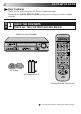
QUICK SET UP GUIDE Dear Customer, CHECK THE CONTENTS CHECK ALL THE CONTENTS SHOWN BELOW 1 Video Cassette Recorder REW SLO W SLOW VCR FF TV CABLE /SAT TIMER 1 LCD PROG AUDIO – –:– – TV/VCR STANDBY/ON JOG SYNCHRO EDIT VIDEO (MONO)L –AUDIO– R TV PROG REC LINK TV PROG SHUTTLE +8 4 0 6 SP 15dB NORM VPS/PDC REVIEW INSERT ENTER/ENTREE 2 1 2 3 4 5 6 A.DUB 30 SEC VCR VPS/PDC DAILY/QTDN.
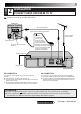
STEP 5 2 INSTALLATION CONNECT VIDEO RECORDER TO TV Place the recorder on a stable, flat surface. Back of TV RF Cable (provided) 21-pin SCART Cable (not provided) Aerial connector 21-pin AV input connector (SCART) TV Aerial Cable (not provided) Make this connection if your TV has a 21-pin AV input connector (SCART) in order to reduce the possibility of interference. And if you are using a stereo TV, you will need this cable in order to enjoy stereo playback of videotapes.
STEP 6 QUICK SET UP GUIDE (cont.) 3 AUTO SET UP SET THE TUNER CHANNELS, CLOCK, GUIDE PROGRAM NUMBERS AND VIDEO CHANNEL* The Auto Set Up function sets the tuner channels, clock, VIDEO Plus+ assigned Guide Program numbers and the video channel* automatically the first time the button on the recorder or on the remote is pressed to turn on the recorder after the mains power cord has been plugged into a mains outlet. * Useful if you have connected the video recorder to your TV via RF connection (Z pg. 5).
PRESET DOWNLOAD SET THE TUNER CHANNELS BY DOWNLOADING FROM YOUR TV, CLOCK AND GUIDE PROGRAM NUMBERS When you connect the recorder and your TV via fully-wired 21-pin SCART cable (Z pg. 5), you can set the recorder's tuner channels by downloading preset data from your TV instead of using the Auto Set Up function (Z pg. 6). After downloading is completed, the recorder sets the clock and VIDEO Plus+ assigned Guide Program numbers automatically. For details, refer to the instruction manual for your TV.
QUICK SET UP GUIDE (cont.) Auto Set Up results appear on the display panel A When both auto channel set and auto clock set have been completed successfully the correct current time will be displayed after the OK button is pressed in item 3 on page 6 or after performing the item 1 on page 7. B When auto channel set has been completed successfully but auto clock set has not, "(PR)1" will be displayed after the OK button is pressed in item 3 on page 6 or after performing the item 1 on page 7.
T-V LINK T-V Link Functions When you connect the recorder and your TV via a fully-wired 21-pin SCART cable (Z pg. 5), the following functions are available. You can use these functions only with a TV offering T-V Link, etc.* For details, refer to the instruction manual for your TV. * Compatible with TVs offering T-V Link, EasyLink, Megalogic, SMARTLINK, Q-Link, DATA LOGIC or NEXTVIEWLINK via fullywired 21-pin SCART cable. The degree of compatibility and available functions may differ by system.
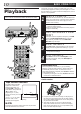
BASIC OPERATIONS The easiest, most basic operation possible with your video recorder is tape playback. Already-recorded signals on a video tape are read by your video recorder and displayed on your TV just like a TV programme. Playback Turn on the TV and select the VIDEO channel (or AV mode).
Still Picture/Frame-By-Frame Playback 1 2 PAUSE DURING PLAYBACK Press PAUSE. If there is vertical jitter, use the TV PROG buttons to correct the picture. ● During still picture, the sound from the previous 3 seconds (approx.) will be played back repeatedly (provided there was at least 6 seconds of normal playback prior to engaging the still picture mode). ● "TIME SCAN AUDIO" must be set to "ON", or the sound will not be heard. (Z pg.
BASIC OPERATIONS (cont.) TV signals being received by the recorder’s built-in tuner can be recorded onto a video tape. You can “capture” a TV programme using your video recorder. Recording Turn on the TV and select the VIDEO channel (or AV mode).
Record One Programme While Watching Another TV RECORD PR O G 1 SELECT PRESET TO WATCH Once recording is in progress, all you need to do is to set the preset controls on the TV for the station you wish to view. ● The programme selected with the TV’s preset controls appears on the TV screen while the one selected with the recorder's TV PROG buttons is recorded on the tape. Elapsed Recording Time Indication You can check the exact time of a recording.
BASIC OPERATIONS (cont.) With VIDEO Plus+, timer programming is greatly simplified because each TV programme has a corresponding code number which your recorder is able to recognise. VIDEO Plus+ Timer 1 Programming – –:– – 1 LCD PROG NUMBER 6 5 PDC 7 8 9 3 1 P+ O ST 4 You can use the remote control with LCD panel to enter the PlusCode number.
4 5 SET TAPE SPEED Press SP/LP ( ) to set the tape speed. SET PDC MODE Press PDC to select "ON" or "OFF". If "VPS/PDC ON" is displayed on the screen or "VPS/ PDC" is lit on the display panel, PDC is set to ON. If "VPS/PDC OFF" is displayed on the screen or "VPS/ PDC" is not lit on the display panel, PDC is set to OFF. Z "PDC Recording" in the column below. ● VPS (Video Programme System) recording is not currently available in the U.K. and not possible with this recorder.
BASIC OPERATIONS (cont.) Express Timer Programming Before performing Express Timer Programming: ● Make sure that the recorder's built-in clock is set properly. ● Insert a cassette with the safety tab in place. The recorder will come on automatically. ● Turn on the TV and select the VIDEO channel (or AV mode). If you don’t know the PlusCode number for the programme you wish to record, use the following procedure to set your recorder to timer-record the programme.
6 ENTER PRESET POSITION Press TV PROG +/– to enter the preset position corresponding to the broadcasting station you wish to record. – P1 – START 21:00 STOP 22:00 = SP VPS/PDC OFF DATE 25.12 TV PROG 1 BBC 1 [+/–] = [PROG] : EXIT SP 7 8 SET TAPE SPEED Press SP/LP ( ) to set the tape speed. SET PDC MODE Press PDC to select "ON" or "OFF". If "VPS/PDC ON" is displayed on the screen or "VPS/ PDC" is lit on the display panel, PDC is set to ON.
BASIC OPERATIONS (cont.) Check, Cancel And Replace Programmes 1 – –:– – 1 2 PDC 1 2 3 4 5 6 7 8 9 SP /L P 2 DISENGAGE TIMER MODE Press ‰, then press . ACCESS PROGRAMME CHECK SCREEN/DISPLAY Press . 3 PR START STOP 1 8:00 10:00 2 10:00 10:45 3 11:30 13:00 4 5 6 7 8 CH 3 2 1 DATE 24.12 25.12 25.12 4 4 0 [ 3 1 ] : NEXT OK 2 TV PROG+/– START+/– ST O P+ /– D AT E+ /– 3 ACCESS PROGRAMME SCREEN/ DISPLAY Press again to check more information.
ADVANCED OPERATIONS Playback Picture Adjustment 0 1 4 4 3 OK Picture Control This feature helps you to adjust the playback picture quality according to your preference. *The default setting is "AUTO." 1 MENU 2 TV PROG 2 3 Manual Tracking Your video recorder is equipped with automatic tracking control. For most tapes this will automatically adjust the tracking to suit the particular tape you are playing. In some circumstances it may be necessary to make manual tracking adjustments.
ADVANCED OPERATIONS (cont.) Playback/ Recording According To Tape Characteristics The B.E.S.T. (Biconditional Equalised Signal Tracking) system checks the condition of the tape in use during recording and playback, and compensates to provide the highest-possible recording and playback pictures. The default setting for both recording and playback is “ON”. 1 2 PLAY Turn on the TV and select the VIDEO channel (or AV mode). B.E.S.T. Picture System 3 Press . ACCESS MAIN MENU SCREEN Press MENU.
Recording 1 START RECORDING Press and hold RECORD and press PLAY on the remote, or press RECORD on the recorder. DURING B.E.S.T. B.E.S.T. COMPLETE Playback The recorder assesses the quality of the tape once you initiate playback. 1 START PLAYBACK Press PLAY. ● The recorder adjusts the playback picture quality based on the quality of the tape in use. ● B.E.S.T. is active during Auto Tracking. “BEST” appears blinking on the recorder’s display panel.
ADVANCED OPERATIONS (cont.) Looking For The Scene You Want Index Search Your recorder automatically marks index codes at the beginning of each recording. This function gives you quick access to any one of 9 index codes in either direction. NOTES: ● Before starting, make sure the recorder is in the Stop mode. ● If "O.S.D." is set to "ON" (Z pg. 41), "MARK" blinks on the screen while an index code is being marked.
Instant ReView Simply by pressing a single button, the recorder power comes on, rewinds, and begins playback of the last timer-recorded programme. If you have several programmes recorded, you can easily access any of them. NOTE: Before starting, make sure that the recorder is off and that the Timer mode is disengaged. – –:– – 1 2 1 2 3 4 5 6 7 8 9 0 1 2 REVIEW 3 4 4 3 1 ACTIVATE INSTANT REVIEW Press REVIEW.
ADVANCED OPERATIONS (cont.) Your recorder is equipped with the TimeScan function. TimeScan allows noise free pictures to be displayed on your TV screen in the forward and reverse search modes. Audio will be played back at normal speed during the TimeScan modes (Z pg. 25). TimeScan also allows you to view a programme in search mode while listening to the audio.
TimeScan Names of special-effects playback Speed SP Speed LP Audio output Reverse Forward Search Play Slow-Motion *Still -9x -7x -5x -3x -1x -1/6x -1/18x 0 1/18x -1/6x -1/18x 0 1/18x Audio is not output. Audio is output. -7x -3x Audio is output. Slow-Motion Play Search 1/6x 1x 2x 3x 5x 7x 9x 1/6x 1x 2x Audio is not output. 5x 9x Audio is output. ** To activate the Still mode from the remote control press PAUSE button.
ADVANCED OPERATIONS (cont.) Selecting The Sound You Want Hi-Fi Audio Recording LEVEL Control In most cases, setting the Hi-Fi audio recording level control to the centre position will provide satisfactory results. If necessary, you can adjust the Hi-Fi audio recording level more precisely by reffering to the audio level indicator on the front panel. 1 2 – –:– – 1 AUDIO2 1 2 3 4 5 6 7 8 9 0 1 3 4 4 3 OK 3 ACCESS MAIN MENU SCREEN Press MENU.
Receiving NICAM Stereo And Bilingual Programmes Your recorder is equipped with a Digital stereo sound decoder (NICAM), making reception of stereo and bilingual broadcasts possible. When the recorder is tuned to a different station, the type of broadcast being received will be displayed on the TV screen for a few seconds.
ADVANCED OPERATIONS (cont.) Automatic Satellite Programme Recording This facility allows you to record automatically a satellite programme which is timer-programmed on your external satellite receiver.
RE C LI N K Before performing the following steps: ● Make sure the satellite receiver is connected to the recorder's AV2 IN/DECODER connector. (Z pg. 28) ● Programme the timer on the satellite receiver. ● Insert a cassette with the safety tab in place. ATTENTION ● Be sure not to turn on the satellite receiver before the programme is executed; otherwise, the recorder will start recording when the satellite receiver's power is turned on.
ADVANCED OPERATIONS (cont.) Remote Control Functions Remote A/B Code Switching The remote control is capable of controlling two JVC video recorders independently; one set to respond to the remote control’s A code control signals and another set to respond to B code control signals. The remote control is preset to send A code signals because your video recorder is initially set to respond to A code signals. You can easily modify your video recorder to respond to B code signals.
TV Multi-brand Remote Control TV Your remote control can operate the basic functions of your TV set. In addition to JVC TVs, other manufacturer’s TVs can also be controlled. Before you start . . . ● Turn off the TV using its remote control. VCR – –:– – 1 2 2 3 4 5 6 7 8 9 0 1 CR /V TV NUMBER 1 1 3 OK 2 2 TV PROG+/– TV +/– Refer to the chart below. Press and hold TV on the recorder's remote control for over 2 seconds, enter your TV’s brand code using the NUMBER keys, then press OK.
ADVANCED OPERATIONS (cont.) CABLE/SAT Satellite Receiver MultiBrand Remote Control VCR Your remote control can operate the basic functions of your satellite receiver set. In addition to JVC satellite receivers, other manufacturer’s satellite receivers can also be controlled. Before you start . . . ● Turn off the satellite receiver using its remote control. – –:– – 1 2 1 2 3 4 5 6 7 8 9 0 1 NUMBER 3 1 4 4 3 Refer to the chart below.
Edit From A Camcorder You can use a camcorder as the source player and your video recorder as the recorder. 1 – –:– – 1 2 1 2 3 4 5 6 7 8 9 0 NUMBER "0" 3 4 4 3 1 2 TV PROG 2 3 4 5 MAKE CONNECTIONS Connect the camcorder’s AUDIO/VIDEO OUT connectors to the recorder’s front panel AUDIO/VIDEO input connectors. ● When using a monaural camcorder, connect its AUDIO OUT connector to the AUDIO L input connector on your recorder.
ADVANCED OPERATIONS (cont.) Synchro Editing The Synchro Editing function synchronizes the start of the playback and recording operations when starting an edit operation using a camcorder equipped with a LANC connector and your video recorder. 1 PAUSE SY N CH RO RE CO RD ED IT 2 3 4 – –:– – 1 2 NUMBER "0" 1 2 3 4 5 6 7 8 9 3 4 4 0 3 1 2 TV PROG Connect your recorder to camcorder (Z pg. 33), and connect your recorder's SYNCHRO EDIT connector to the camcorder's LANC connector.
You can use your video recorder as the source player or as the recording deck. Edit To Or From Another 1 Video Recorder 2 – –:– – 1 2 NUMBER "0" 1 1 2 3 4 5 6 7 8 9 0 3 4 4 3 2 TV PROG 3 4 5 MAKE CONNECTIONS Connect the player’s 21-pin SCART connector to the recorder’s 21-pin SCART connector as illustrated on page 36. A When Using Your Video Recorder As The Source Player ... ... connect its AV1 IN/OUT connector to the recording deck.
ADVANCED OPERATIONS (cont.) A B Player TV Receiver Your recorder SYNCHRO EDIT Recorder JLIP SYNCHRO EDIT ANT. IN AV1 IN/OUT AV1 IN/OUT L AUDIO OUT R R PAUSE AV2 IN/DECODER RF OUT VIDEO CHANNEL or AV mode 21-pin SCART Cable (not provided) RF Cable (provided) PAUSE RF OUT 21-pin SCART Cable (not provided) Another recorder Recorder JLIP ANT.
PLAY Audio Dubbing Audio dubbing replaces the normal audio sound of a previously recorded tape with a new soundtrack. Normal audio track Pre-recorded tape Video/Hi-Fi audio track Audio-dubbed tape STOP PAUSE TV A. D U G B O PR 1 CD Player etc. CD Player etc. Mixer output Audio mixer Original sound AUDIO OUT NOTES: ● When monitoring the sound during Audio Dubbing, the normal soundtrack is automatically selected.
ADVANCED OPERATIONS (cont.) Your recorder G O PR PA U SE TV TIME SCAN SHUTTLE Recorder JOG Insert Editing Insert editing replaces part of the recorded scene with new material. Both the picture and Hi-Fi audio soundtrack are replaced with new ones, while the normal audio soundtrack remains unchanged. If you wish to change the normal audio track as well, use the audio dubbing function simultaneously. Use your video recorder as the recorder.
PLAY 6 B IN SE U RT D A. 7 ENGAGE INSERT EDITING Press INSERT. ● Your recorder enters the Insert-Pause mode. (" ", " and " " light up on the front display panel.) ● The TV screen changes from the still picture to the input source you are going to record. START EDITING Load the source cassette and play back the segment that is to be inserted.
ADVANCED OPERATIONS (cont.) Information On J Terminal J Terminal (JLIP(Joint Level Interface Protocol) Connector) The J Terminal is used to connect the recorder to a personal computer or similar device to allow computerized control of the recorder during editing and certain other operations. Examples: With the optional JLIP VIDEO CAPTURE BOX GV-CB3E: ● Enables Random Assemble Editing of up to 99 segments, using this recorder as the playback unit.
On-Screen Display Other Functions You can choose whether or not to have various operational indicators appear on screen, by setting this function ON or OFF. Turn on the TV and select the VIDEO channel (or AV mode). 1 2 – –:– – 1 2 1 2 3 3 4 5 6 7 8 9 3 4 4 0 3 1 OK MENU 2 4 ACCESS MAIN MENU SCREEN Press MENU. ACCESS MODE SET SCREEN Move the highlight bar (pointer) to "MODE SET" by pressing %fi, then press OK or #.
ADVANCED OPERATIONS (cont.) Power Save Mode You can reduce the power consumption while the recorder is turned off. 1 2 – –:– – 1 2 1 2 3 4 5 6 7 8 9 0 1 ACCESS MAIN MENU SCREEN Press MENU. ACCESS MODE SET SCREEN Press %fi to move the highlight bar (pointer) to "MODE SET", then press OK or #.
Auto SP→LP Timer Auto Timer If, when timer-recording in SP mode, there is not enough tape to record the entire programme, the recorder automatically switches to LP mode to allow complete recording. For Example . . . Recording a programme of 210 minutes in length onto a 180minute tape Approximately 150 minutes Approximately 60 minutes SP mode LP mode Total 210 minutes Make sure you set "AUTO SP→LP TIMER" to "ON" at the Mode Set screen before the timer-recording starts.
ADVANCED OPERATIONS (cont.) Repeat Playback Your video recorder can automatically play back the whole tape 50 times repeatedly. – –:– – 1 2 1 2 3 4 5 6 7 8 9 3 4 4 0 3 1 2 AY PL FF 1 2 REW PAUSE STOP 3 START PLAYBACK Press PLAY. ACTIVATE REPEAT PLAYBACK Press PLAY and hold for over 5 seconds, then release. ● The Play indicator ( ) on the display panel blinks slowly. ● The tape plays 50 times automatically, and then stops. STOP PLAYBACK Press STOP at any time to stop playback.
SYSTEM CONNECTIONS Connection To A Stereo System These instructions enable you to connect your video recorder to your Hi-Fi stereo system (if you have one) and listen to the soundtrack through the stereo. FM Tuner CD Player Stereo Amplifier I I I I I I I I I I I I I I I I I I I I I I I I I I I I I I I I I I I I I I I AUX IN or TAPE MONITOR I I I I Audio Cable (not provided) Speaker Television Speaker SYNCHRO EDIT JLIP ANT.
SUBSIDIARY SETTINGS Video Channel Set Video Channel (RF Output Channel) is the channel on which your TV receives picture and sound signals from the video recorder through the RF cable. IMPORTANT Perform the following steps only if — — Video Channel Set has not been done correctly by the Auto Set Up function (Z pg. 6). — interference appears in the TV picture after you have moved to a different area or a new station has started broadcasting in your area.
With RF Connection Before performing the following procedure, make sure that: STOP n the mains power cord is plugged into the mains outlet. n the video recorder is turned off and there is no cassette inserted in the recorder. n the connected TV is turned on. n batteries have been installed in the remote control. 1 2 – –:– – 1 2 1 2 3 4 5 6 7 8 9 0 1 ACCESS VIDEO CHANNEL SET MODE Press and hold down STOP on the recorder until the display panel shows the following.
SUBSIDIARY SETTINGS (cont.) IMPORTANT Tuner Set Turn on the TV and select the VIDEO channel (or AV mode). Perform the following steps only if — — Auto Channel Set has not been set correctly by Auto Set Up function (Z pg. 6) or Preset Download (Z pg. 7). — you have moved to a different area or if a new station starts broadcasting in your area. Your recorder needs to memorise all necessary stations in preset positions in order to record TV programmes.
After "SCAN COMPLETED" PR CH ID PR CH ID is displayed on the screen 01 26 BBC1 08 –––– 02 33 BBC2 09 –––– for about 5 seconds, a 03 23 ITV 10 –––– Confirmation screen 04 30 CH4 11 –––– –––– looking like the one on the 05 37 CH5 12 06 –––– 13 –––– right appears. The stations 07 –––– 14 –––– [5∞ ] your recorder located : EDIT = appear on a Confirmation = [X] : DELETE screen — preset positions [MENU] : EXIT (PR), channels (CH) and station names (ID – Z pg. 53).
SUBSIDIARY SETTINGS (cont.) 4 SELECT BAND Press %fi to change the band between CH (regular) and CC (cable), then press #. PR CH ID FINE DECODER 06 CH01 – – – – +/– OFF ∞ ∞ [5∞] : SELECT [ ] : CURSOR += : OK [MENU] : EXIT – –:– – 1 2 NUMBER 1 2 3 4 5 6 7 8 9 The blueback screen and the programme currently being broadcast by the selected channel appear alternately for 8 seconds each. 3 5 4 4 0 3 1 OK MENU Press the NUMBER keys to input the channel number you want to store.
Delete A Channel Perform steps 1 and 2 of "Storing Channels Manually" on page 50 to access the Confirmation screen before continuing. 1 2 3 Perform steps 1 and 2 of "Storing Channels Manually" on page 50 to access the Confirmation screen before continuing. SELECT ITEM Press %fi @ # until the item you want to delete begins blinking. DELETE CHANNEL Press . ● The item directly beneath the cancelled one moves up one line. ● Repeat steps 1 and 2 as necessary. CLOSE CONFIRMATION SCREEN Press MENU.
SUBSIDIARY SETTINGS (cont.) Set Stations (A) Set Stations (B) Set station names that are registered in your recorder. Set station names other than the ones registered in your recorder. Perform steps 1 and 2 of "Storing Channels Manually" on page 50 to access the Confirmation screen before continuing. 5 1 Press # until the first letter of the station name begins blinking.
TV Station And ID List STATION NAME ID* STATION NAME ID* Anglia TV ARD ARTE BBC Group BBC1 BBC2 Berlin 1 Berlin 2 Border TV Bayern1 Bayern3 BRT1 BRT2 Children Ch Canal + CNN Channel TV Central TV Channel 4 Channel 5 DRS DR TV DSF Euronews Euronews Eurosports France1 France2 France3 Granada TV Grampian TV Hessen1 Hessen3 HRT HTV ITV Network Kabelkanal London MDR MTV Nord3 NDR1 NDR3 NED1 NED2 NED3 Network 2 NRK N-TV Offener Kanal ORF1 ORF2 ORF3 OWL 3 Premiere PR07 RAI1 RAI2 RAI3 RB1 RB3 Rikisutvarpid-S
SUBSIDIARY SETTINGS (cont.) TV Station Channel Number Guide For customers in the U.K. Only the main stations are listed. There are in addition many relay stations, and full lists are available from the BBC and ITV. BBC1 BBC2 ITV CH4 CH5 London & South-East Bluebell Hill ......................... Crystal Palace ....................... Dover ................................... Heathfield ............................ Oxford .................................
IMPORTANT Clock Set Turn on the TV and select the VIDEO channel (or AV mode). – –:– – 1 2 1 2 3 4 5 6 7 8 9 0 1 3 4 4 3 OK MENU 2 If you performed Auto Set Up (Z pg. 6), Preset Download (Z pg. 7) or Auto Channel Set (Z pg. 48), without ever having set the clock previously, the recorder's built-in clock is also set automatically. Perform the following steps only if — — Auto Clock Set has not been performed correctly by Auto Set Up, Preset Download or Auto Channel Set.
SUBSIDIARY SETTINGS (cont.) VIDEO Plus+ Setup IMPORTANT Normally, Auto Set Up (Z pg. 6), Preset Download (Z pg. 7) or Auto Channel Set (Z pg. 48) sets the Guide Program Numbers automatically. You need to set the Guide Program Numbers manually only in the following cases. ● When timer-programming with VIDEO Plus+, the preset position, where the station you wish to record is received on your recorder, is not selected or when you add a channel after Auto Set Up or Auto Channel Set has taken place.
SUBSIDIARY INFORMATION Questions And Answers PLAYBACK TIMER RECORDING Q. What happens if the end of the tape is reached during playback or search? A. The tape is automatically rewound to the beginning. Q. " " and "‰" remain lit on the display panel. Is there a problem? A. No. This is a normal condition for a timer recording in progress. ○ ○ ○ ○ ○ ○ ○ ○ ○ ○ ○ ○ ○ ○ ○ ○ ○ ○ ○ ○ ○ ○ ○ ○ ○ ○ ○ ○ ○ Q. Can the video recorder indefinitely remain in the still mode? A. No.
SUBSIDIARY INFORMATION (cont.) Troubleshooting Before requesting service for a problem, use this chart to see if you can correct the trouble yourself. Small problems are often easily corrected, and this can save you the trouble of sending your video recorder off for repair. POWER SYMPTOM POSSIBLE CAUSE CORRECTIVE ACTION 1. No power is applied to the recorder. ● The mains power cord is disconnected. Connect the mains power cord. 2.
4. Camcorder recording is not possible. ● The camcorder has not been properly connected. ● The input mode is not correct. Confirm that the camcorder is properly connected. Set the input mode to “L-1”,“L-2” or “F-1”. TIMER RECORDING SYMPTOM POSSIBLE CAUSE CORRECTIVE ACTION 1. Timer recording won’t work. ● The clock and/or the timer have been set incorrectly. ● The timer is not engaged. Re-perform the clock and/or timer settings. Press ‰ and confirm that “‰“ is displayed on the display panel. 2.
SUBSIDIARY INFORMATION (cont.) Index FRONT VIEW 1 23 4 5 6 7 REW W SLO SLOW FF TIMER STANDBY/ON JOG SYNCHRO EDIT VIDEO (MONO)L –AUDIO– R TV PROG REC LINK 15dB NORM TV PROG 890 ! @ # SHUTTLE +8 4 0 6 SP VPS/PDC REVIEW INSERT A.DUB VCR $ 1 STANDBY/ON Button turns recorder on/off (loading a cassette also turns power on). 2 TIMER Button engages timer-standby mode. Z pg. 15, 17 3 REVIEW Button "reviews" timer-recorded programme. Z pg.
REAR VIEW 2 1 3 4 SYNCHRO EDIT 5 JLIP ANT. IN AV1 IN/OUT L AUDIO OUT R AV2 IN/DECODER PAUSE RF OUT 6 1 Mains Power Cord supplies power to recorder. Z pg. 5 2 AV1 IN/OUT Connector enables AV connection to TV or second recorder; input recordable when "L-1" selected. Z pg. 5, 35 3 J Terminal (JLIP (Joint Level Interface Protocol) Connector) enables connection of a personal computer or similar device to allow computerized control of the recorder during editing and certain other operations.
SUBSIDIARY INFORMATION (cont.) REMOTE CONTROL 1 2 3 4 5 6 7 8 9 0 ! @ # VCR TV 1 LCD PROG AUDIO CABLE /SAT – –:– – TV/VCR ENTER/ENTREE 2 1 2 3 30 SEC 4 5 6 VPS/PDC DAILY/QTDN. WEEKLY/HEBDO 7 8 0000 AUX 9 3 4 4 0 MENU 1 PROG OK 3 2 START DEBUT STOP FIN DATE TV PROG EXPRESS $ % ^ * ( ) q w e r t y u i o p Q W 1 LCD Panel indicates which of the recorder, TV and satellite tuner the remote control can currently operate Z pg.
* CABLE/SAT Button enables remote control of connected satellite receiver. Z pg. 32, “Remote Control LCD” in the right column ( STANDBY/ON Button — same as button on recorder. ) – –:– – (DISPLAY) Button switches display between clock time, tape remaining time, counter readings and preset position*. Z pg. 13 * Preset position is not displayed during playback. q TV/VCR Button switches connected TV's mode between TV and AV. Z pg. 10 w REVIEW Button — same as button on recorder. Z pg.
SPECIFICATIONS VIDEO/AUDIO Signal system Recording system Signal-to-noise ratio Horizontal resolution Frequency range Input/Output : PAL-type colour signal and CCIR monochrome signal, 625 lines/50 fields : DA4 (Double Azimuth) helical scan system : 45 dB : 250 lines : 70 Hz to 10,000 Hz (Normal audio) 20 Hz to 20,000 Hz (Hi-Fi audio) : 21-pin SCART connectors (IN/OUT x 1, IN/DECODER x 1) RCA connectors (VIDEO IN x 1, AUDIO IN x 1, AUDIO OUT x 1) TUNER/TIMER TV channel storage capacity Tuning system Chan