ENGLISH SEE AUTO SET UP ON REAR SIDE CONTENTS SAFETY FIRST 2 Safety Precautions ................................... 2 VIDEO CASSETTE RECORDER HR-S8500E/EH INSTALLING YOUR NEW RECORDER 4 Basic Connections ................................... 4 S-VIDEO Connection .............................. 5 INITIAL SETTINGS 6 Auto Set Up ............................................ 6 Language ................................................ 9 On-Screen Displays ..............................
EN SAFETY FIRST Safety Precautions The rating plate and the safety caution are on the rear of the unit. WARNING: DANGEROUS VOLTAGE INSIDE WARNING: TO PREVENT FIRE OR SHOCK HAZARD, DO NOT EXPOSE THIS UNIT TO RAIN OR MOISTURE. CAUTION n When you are not using the recorder for a long period of time, it is recommended that you disconnect the power cord from the mains outlet. n Dangerous voltage inside. Refer internal servicing to qualified service personnel.
EN 3 For Italy: "It is declared that this product, brand JVC, conforms to the Ministry Decree n. 548 of 28 Aug.'95 published in the Official Gazette of the Italian Republic n. 301 of 28 Dec.'95" The STANDBY/ON current on and off. " button does not completely shut off mains power from the unit, but switches operating " shows electrical power standby and " " shows ON. Video tapes recorded with this video recorder in the LP (Long Play) mode cannot be played back on a singlespeed video recorder.
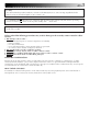
EN INSTALLING YOUR NEW RECORDER It's essential that your video recorder be properly connected. Follow these steps carefully. THESE STEPS MUST BE COMPLETED BEFORE ANY VIDEO OPERATION CAN BE PERFORMED. Basic Connections Aerial terminal Back of TV 21-pin SCART connector RF Cable (provided) TV Aerial Cable 1 2 3 The connection method you use depends on the type of TV you have.
EN 5 S-VIDEO Connection Back of TV Aerial terminal S-VIDEO IN connector S-Video cable (not provided) AUDIO IN connectors Aerial or Cable Audio cable (not provided) Mains outlet ANT. IN S VIDEO OUT AUDIO OUT Mains Power Cord ANT. IN AV1 OUT IN AV1 IN/OUT OUT S VIDEO COMP. Y/C R L AUDIO OUT RF OUT AV2 IN/DECODER PAUSE/ R.A. EDIT Back of Recorder RF OUT RF Cable (provided) ● To Connect to A TV With S-VIDEO/AUDIO IN Connectors . . .
EN INITIAL SETTINGS Auto Set Up Auto Channel Set/Auto Clock Set/Auto Guide Program Number Set/Auto Video Channel Set When the button on the recorder/remote control is pressed for the first time to power on the recorder after you plug the mains power cord into a mains outlet, the Country Set display will appear on the TV screen and the recorder's front display panel.
EN 3 SELECT LANGUAGE Press OK. The Language Set display appears on the front display panel and/or on the screen. If you are referring to the front display panel Press %fi to select your language code. Language Code ENGLISH : 01 DEUTSCH : 02 FRANCAIS : 03 ITALIANO : 04 CASTELLANO : 05 NEDERLANDS SVENSKA NORSK SUOMI DANSK : 06 : 07 : 08 : 09 : 10 Press %fi to move the highlight bar (pointer) to the language of your choice.
EN INITIAL SETTINGS (cont.) Auto Set Up results appear on the front display panel A B C When both auto channel set and auto clock set have been completed successfully the correct current time will be displayed after the OK button is pressed in step 6 on page 7. When auto channel set has been completed successfully but auto clock set has not, "1" (channel position) will be displayed after the OK button is pressed in step 6 on page 7.
EN This recorder offers you the choice to view on-screen messages in 10 different languages. Though Auto Set Up selects the language automatically (Z pg. 8), you can change the language setting manually using this procedure as required. Language Turn on the TV and select the VIDEO channel (or AV mode). – –:– – 1 2 3 4 5 6 7 8 9 1 2 3 Press %fi to move the highlight bar (pointer) to "AUTO CH SET", then press OK or . 4 . ACCESS MAIN MENU Press MENU.
EN INITIAL SETTINGS (cont.) You can choose whether or not to have various operational indicators appear on screen, by setting this function ON or OFF. Messages appear in the selected language (Z pg. 8 or 9). On-Screen Displays 1 2 3 Press MENU. 4 The default setting is “ON”, so if you want on-screen displays, leave the setting as it is and go to step 5. If you don’t want the displays to appear, press %fi to move the highlight bar (pointer) to "O.S.D." and press OK or to set “O.S.D.” to “OFF”.
EN Power Save Mode (HR-S8500E only) Turn on the TV and select the VIDEO channel (or AV mode). – –:– – 2 3 4 5 6 7 8 9 X 0 You can reduce the power consumption while the recorder is turned off. TURN ON THE RECORDER 1 Press 2 3 Press MENU. . ACCESS MAIN MENU SCREEN ACCESS MODE SET SCREEN Press %fi to move the highlight bar (pointer) to "MODE SET", then press OK or . % 1 2 MAIN MENU MODE SET AUTO CH SET MANUAL CH SET INITIAL SET REC LEVEL CTL R.A.
EN INFORMATION ON COLOUR SYSTEM Colour System Set 2 3 4 5 6 7 8 9 2 X 0 * SECAM signals will be recorded as MESECAM on this recorder; MESECAM is the designation for tapes with SECAM signals that have been recorded on a MESECAM-compatible PAL video cassette recorder. 4 TURN ON THE RECORDER Press . ACCESS MAIN MENU SCREEN Press MENU. ACCESS MODE SET SCREEN Press %fi to move the highlight bar (pointer) to "MODE SET", then press OK or .
PLAYBACK EN The easiest, most basic operation possible with your video recorder is tape playback. Already-recorded signals on a video tape are read by your video recorder and displayed on your TV just like a TV programme. Basic Playback Turn on the TV and select the VIDEO channel (or AV mode).
EN PLAYBACK (cont.) Still Picture/Frame-By-Frame Playback Playback Features PLAY JOG 1 8 5/8 1 ¡ RE FF W q TIME SCAN SHUTTLE 6 PAUSE 2 PAUSE DURING PLAYBACK Press PAUSE. ● During still picture, the sound from the previous 3 seconds (approx.) will be played back repeatedly (provided there was at least 6 seconds of normal playback prior to engaging the still picture mode). However, the TIME JOG & SCAN indicator will not light.
EN High-Speed (Turbo) Search 1 ACTIVATE HIGH-SPEED SEARCH During playback or still, press FF for forward highspeed search, or REW for reverse high-speed search. To resume normal playback, press PLAY. NOTE: Index Search Your recorder automatically marks index codes at the beginning of each recording. This function gives you quick access to any one of 9 index codes in either direction. Before starting, make sure the recorder is in the Stop mode. ACTIVATE INDEX SEARCH Press or (™ or £).
EN PL TA LT BC / AY NR PLAYBACK (cont.) Digital 3R picture system applies edge correction to the luminance signal to enhance detail. DI GI 8 Digital 3R 5/8 6 q ¡ SP AT IA LI ZE R REW 1 1 Press MENU. 2 Move the highlight bar (pointer) to "MODE SET" by pressing %fi, then press OK or .
EN 17 SpatializerW Repeat Playback This feature expands sound field when you play back any stereo source or view a stereo programme while recording it. *SpatializerW has no effect on recording quality. Your video recorder can automatically play back the whole tape 50 times repeatedly. 1 ACTIVATE SPATIALIZERW Press SPATIALIZER; the current setting will be displayed on the screen for about 5 seconds. Pressing SPATIALIZER while the screen shows the display changes the setting.
EN PLAYBACK (cont.) TIME SCAN SHUTTLE PLAY TV PROG TimeScan 8 5/8 6 PAUSE q 1 Your recorder is equipped with the TimeScan function. TimeScan allows noise free pictures to be displayed on your TV screen in the forward and reverse search modes. Audio will be played back at normal speed during the TimeScan modes (Z pg. 19). TimeScan also allows you to view a programme in search mode while listening to the audio.
EN 19 TimeScan Reverse Names of special-effects playback Speed SP Search -9x Speed LP Audio output Play Slow-Motion (Time Jog**) *Still Slow-Motion (Time Jog**) Play Search -1x -1/2x 0 1/2x 1x 1.5x 2x 3x 5x 7x 9x -1/2x 0 1/2x 1x 1.5x 2x Audio is not output. Audio is output. Audio is output. -7x -5x -3x -7x Forward -3x Audio is output. ● ● ● ● ● ● ● ● ● ● ● ● ● ● ● ● 9x Audio is output. % fi ● ● 5x ** Still mode cannot be engaged using the remote control's or button.
EN RECORDING TV signals being received by the recorder’s built-in tuner can be recorded onto a video tape. You can “capture” a TV programme using your video recorder. Basic Recording 1 2 Press TV PROG +/– or the NUMBER keys to select the channel you wish to record. 3 4 Press SP/LP ( ). Check the SP/LP indicator on the recorder display panel to confirm the selected tape speed. PLAY TV PROG Turn on the TV and select the VIDEO channel (or AV mode).
EN 21 Record One Programme While Watching Another Recording Features TV PR O G If your recorder is connected to the TV via AV connection, . . . . . . press TV/VCR. The recorder's VCR indicator and the TV broadcast being recorded disappear. 8 5/8 6 q 1 ¡ RECORD 1 – –:– – – –:– – SELECT CHANNEL TO WATCH Once recording is in progress, all you need to do is to set the channel controls on the TV for the station you wish to view.
EN RECORDING (cont.) S-VHS (Super VHS) and VHS – –:– – 1 2 3 4 5 6 7 8 9 X 0 AUDIO Your recorder can record in either S-VHS or VHS. To record in S-VHS: Perform the steps 1 – 4 below to set "S-VHS" to "AUTO". Then, insert a cassette marked "S-VHS", the S-VHS indicator will light on the display panel. The S-VHS recording mode will be selected. 2 To record in VHS: Insert a cassette marked "VHS". The VHS recording mode will be automatically selected regardless of the S-VHS mode setting.
EN 23 Hi-Fi Audio Recording Level Control Receiving Stereo And Bilingual Programmes Your recorder allows manual adjustment of the Hi-Fi audio recording level. Normally the preset audio recording level is satisfactory, but if the sound you are going to record is too loud or too low, adjust the audio recording level while referring to the recorder's audio level meters.
EN RECORDING (cont.) B.E.S.T. Picture System PLAY Turn on the TV and select the VIDEO channel (or AV mode). 8 5/8 6 PAUSE 1 ¡ RE CO RD q The B.E.S.T. (Biconditional Equalised Signal Tracking) system checks the condition of the tape in use during recording and playback, and compensates to provide the highest-possible recording and playback pictures. The default setting for both recording and playback is “ON”. Preparation TURN ON THE RECORDER 1 Press 2 3 Press MENU. .
EN Recording 1 START RECORDING Press and hold RECORD and press PLAY on the remote, or press RECORD on the recorder. DURING B.E.S.T. B.E.S.T. COMPLETE 25 Playback The recorder assesses the quality of the tape once you initiate playback. 1 START PLAYBACK Press PLAY. ● The recorder adjusts the playback picture quality based on the quality of the tape in use. ● B.E.S.T. is active during Auto Tracking. “BEST” appears blinking on the recorder’s display panel.
EN TIMER RECORDING With SHOW VIEW , timer programming is greatly simplified because each TV programme has a corresponding code number which your recorder is able to recognize. SHOWVIEW Timer 1 Programming The front display panel looks like this: 2 ENTER SHOWVIEW NUMBER Press the NUMBER keys to enter the SHOWVIEW number of a programme you wish to record. ● If you make a mistake, press and input the correct number.
EN VPS/PDC LY – –:– – 2 3 4 5 6 7 8 9 X 0 D AI 1 2 STOP+/– PROG SET TAPE SPEED 4 5 Press SP/LP ( 6 Press PROG or OK. "PROGRAM COMPLETED" appears on the screen for about 5 seconds, then normal screen appears. 7 Press ‰. The recorder turns off automatically and ‰ appears on the display panel. WEEKLY 4 27 1 ) to set the tape speed. SET VPS/PDC MODE Press VPS/PDC to select "ON" or "OFF".
EN TIMER RECORDING (cont.) Express Timer Programming Before performing Express Timer Programming: ● Make sure that the recorder's built-in clock is set properly. ● Insert a cassette with the safety tab in place. The recorder will come on automatically. ● Turn on the TV and select the VIDEO channel (or AV mode). If you don’t know the SHOW VIEW number for the programme you wish to record, use the following procedure to set your recorder to timer-record the programme.
EN 6 ENTER CHANNEL POSITION Press TV PROG +/–. – P1 – START 21:00 STOP 22:00 = SP VPS/PDC OFF DATE 25.12 TV PROG 1 ARD [+/–] = [PROG] : EXIT SP 7 8 9 SET TAPE SPEED Press SP/LP ( ) to set the tape speed. SET VPS/PDC MODE Press VPS/PDC to select "ON" or "OFF". If "VPS/PDC ON" is displayed on the screen or "VPS/ PDC" is lit on the display panel, VPS/PDC is set to ON. If "VPS/PDC OFF" is displayed on the screen or "VPS/PDC" is not lit on the display panel, VPS/PDC is set to OFF.
EN TIMER RECORDING (cont.) Check, Cancel And Replace Programmes – –:– – 1 2 3 4 5 6 8 9 1 2 Press 7 X STOP+/– 2 VPS/PDC 0 4 DISENGAGE TIMER MODE Press ‰, then press . ACCESS PROGRAMME CHECK SCREEN/DISPLAY . TV PROG+/– START+/– PR START STOP 1 8:00 10:00 2 10:00 10:45 3 11:30 13:00 4 5 6 7 8 CH 3 2 1 DATE 24.12 25.12 25.12 D AT E+ 1 [ /– ] : NEXT P /L SP OK 3 + MENU V TV T – T V PROG – 3 ACCESS PROGRAMME SCREEN/ DISPLAY Press again to check more information.
EN 31 Auto SP→LP Timer Auto Timer If, when timer-recording in SP mode, there is not enough tape to record the entire programme, the recorder automatically switches to LP mode to allow complete recording. For Example . . . Recording a programme of 210 minutes in length onto a 180minute tape When the Auto Timer is set to ON the timer is automatically engaged when the recorder power is turned off and automatically disengaged when the recorder is powered back on.
EN TIMER RECORDING (cont.) This facility allows you record automatically a satellite programme which is timer-programmed on your external satellite tuner. Connect a satellite tuner to the recorder's AV2 IN/DECODER connector and programme the timer on the satellite tuner; the recorder starts recording when the signals input from the satellite tuner to the AV2 IN/DECODER connector, and when there is no input signals the recorder stops recording and the power shuts off.
SPECIAL FEATURES EN Remote A/B Code Switching Remote Control Functions VCR The remote control is capable of controlling two JVC video recorders independently; one set to respond to the remote control’s A code control signals and another set to respond to B code control signals. The remote control is preset to send A code signals because your video recorder is initially set to respond to A code signals. You can easily modify your video recorder to respond to B code signals.
EN SPECIAL FEATURES (cont.) SAT TV Multi-brand Remote Control TV Your remote control can operate the basic functions of your TV set. In addition to JVC TVs, other manufacturer’s TVs can also be controlled. Before you start . . . ● Turn on the TV using its remote control. VCR – –:– – TV/VCR 1 2 3 4 5 6 7 8 9 X 0 2 NUMBER 4 1 SET TV BRAND CODE Refer to the chart below.
EN 35 SAT Satellite Tuner Multi-Brand Remote Control TV Your remote control can operate the basic functions of your satellite tuner set. In addition to JVC satellite tuners, other manufacturer’s satellite tuners can also be controlled. Before you start . . . ● Turn on the satellite tuner using its remote control. VCR – –:– – 1 2 3 4 5 6 7 8 9 X 0 2 NUMBER 4 1 SET SATELLITE TUNER BRAND CODE Refer to the chart below.
EN EDITING Preparation For Editing Turn on the TV and select the VIDEO channel (or AV mode). 1 2 3 4 5 6 7 8 9 X 0 You can minimize picture degradation while editing. 1 2 ACCESS MAIN MENU SCREEN Press MENU. ACCESS MODE SET SCREEN Move the highlight bar (pointer) to "MODE SET" by pressing %fi, then press OK or . % – –:– – Editing Mode Setting MAIN MENU MODE SET AUTO CH SET MANUAL CH SET INITIAL SET REC LEVEL CTL R.A. EDITT 2 [5∞] = [MENU] : EXIT 4 MODE SET AUTO TIMER OFF O. S. D.
EN Edit From A Camcorder You can use a camcorder as the source player and your video recorder as the recorder. MAKE CONNECTIONS 1 A If the camcorder has no S-VIDEO output connector... ... connect the camcorder’s AUDIO/VIDEO OUT connectors to the recorder’s front panel AUDIO/ VIDEO input connectors. B If the camcorder has an S-VIDEO output connector... ... connect the camcorder’s S-VIDEO OUT and AUDIO OUT connectors to the recorder’s rear panel S VIDEO and front panel AUDIO input connectors.
EN EDITING (cont.) You can use your video recorder as the source player or as the recording deck. Edit To Or From Another 1 Video Recorder 2 – –:– – 1 2 3 2 NUMBER "0" 4 5 6 7 8 9 X 0 4 1 OK 3 + MENU V TV T T V PROG – SET RECORDING DECK’S INPUT MODE Set to AUX. With this video recorder, press NUMBER key "0" and/or TV PROG to select “L-1” for the AV1 IN/ OUT connector, or “L-2” for the AV2 IN/DECODER connector, depending on the connector being used.
EN TV Receiver VIDEO CHANNEL or AV mode Player Your recorder Recorder Your recorder 21-pin SCART Cable (not provided) 21-pin SCART Cable (not provided) RF Cable (provided) Another recorder Recorder TV Receiver RF Cable (provided) VIDEO CHANNEL or AV mode Another recorder Player AV2 SELECT Setting fi fi Set "AV2 SELECT" to the appropriate mode depending on the type of unit connected to the rear panel AV2 IN/ DECODER connector of this recorder. 1 Press MENU to access the Main Menu screen.
EN EDITING (cont.) Insert Editing Recorder Your recorder Insert editing replaces part of the recorded scene with new material. Both the picture and Hi-Fi audio soundtrack are replaced with new ones, while the normal audio soundtrack remains unchanged. If you wish to change the normal audio track as well, use the audio dubbing function simultaneously. Use your video recorder as the recorder.
PLAY EN 6 7 Load the source cassette and play back the segment that is to be inserted. When you reach the start of the section of the source tape that you wish to insert, press PLAY to start the tape in your recorder; Insert Editing begins at this point. 5/8 6 B U D RT A. IN SE 1 ENGAGE INSERT EDITING Press INSERT. 8 q ¡ ● Your recorder enters the Insert-Pause mode. (" ", " " and " " light up on the front display panel.
EN EDITING (cont.) This function makes it easier to create edited videos when your video recorder is used as the source player in combination with another JVC video recorder equipped with a Remote PAUSE Connector. You can pre-program up to 8 scenes or “cuts” for automatic editing in the sequence you have specified. You can also perform Random Assemble Editing with a second non-JVC recorder. Z pg. 43 Random Assemble Editing 1 PAUSE/ R.A.
EN Find the point on the source tape from where you want the edited scene to begin by pressing or using the TIME SCAN SHUTTLE ring or the JOG dial, then press PROG. =1 2 3 4 5 6 7 8 % fi 8 LOCATE EDIT-IN POINT 0:00:00 (+) 0:00:00 ● The edit-in point is registered in memory and appears on the screen. LOCATE EDIT-OUT POINT Find the point where you want the edited scene to end by pressing or using the TIME SCAN SHUTTLE ring or the JOG dial, then press PROG.
EN EDITING (cont.) Normal audio track Pre-recorded tape TV PL PR O AY G Audio Dubbing Audio dubbing replaces the normal audio sound of a previously recorded tape with a new soundtrack. 8 Video/Hi-Fi audio track 5/8 6 q 1 ¡ A. Audio-dubbed tape PAUSE B U D CD Player etc. CD Player etc.
PLAY EN 5 6 Press STOP to stop the tape in your recorder, and engage the audio component's Stop mode. 5/8 6 ¡ PA STOP U SE 1 START DUBBING Engage the audio component's Play mode, then press PLAY to start the tape in your recorder. Audio dubbing begins at this point. 8 q ● " " blinks and " " is displayed on the front display panel. ● To stop dubbing temporarily, press PAUSE. Press PLAY to resume dubbing.
EN SYSTEM CONNECTIONS Connection To A Satellite Tuner The AV2 IN/DECODER connector on the rear panel of your recorder allows simple connection to a satellite tuner. Aerial connector Aerial Outdoor Unit Back of TV Satellite Cable 21-pin AV input connector (SCART) TV Aerial cable Satellite Tuner Unit ANT. IN DECODER VCR EXT.2 TV EXT.1 RF OUT Mains outlet ANT. IN AV1 OUT IN AV1 IN/OUT OUT COMP. Y/C S VIDEO R L AUDIO OUT RF OUT AV2 IN/DECODER PAUSE/ R.A.
EN Connecting/ Using A Decoder TV Receiver RF Cable (provided) TV Aerial Cable 47 The AV2 IN/DECODER connector can be used as an input terminal for an external decoder (descrambler). Simply connect a decoder and you can enjoy the variety of programming that is available through scrambled channels. 1 2 3 SELECT INPUT MODE Set "AV2 SELECT" to "DECODER". (Z pg. 39) CONNECT DECODER Connect your recorder's AV2 IN/DECODER connector to the decoder's Euroconnector using a 21-pin SCART cable.
EN SYSTEM CONNECTIONS (cont.) These instructions enable you to connect your video recorder to your Hi-Fi stereo system (if you have one) and listen to the soundtrack through the stereo. Connecting/ Using A Stereo System FM Tuner CD Player Stereo Amplifier I I I I I I I I I I I I I I I I I I I I I I I I I I I I I I I I I I I I I I I AUX IN or TAPE MONITOR I I I I Audio Cable (not provided) Speaker Television Speaker ANT. IN AV1 OUT IN S VIDEO Mains outlet AV1 IN/OUT OUT COMP.
SUBSIDIARY SETTINGS EN 49 Video Channel Set Video Channel (RF Output Channel) is the channel on which your TV receives picture and sound signals from the video recorder through the RF cable. IMPORTANT Perform the following steps only if — — Video Channel Set has not been done correctly by the Auto Set Up function (Z pg. 6). — interference appears in the TV picture after you have moved to a different area or a new station has started broadcasting in your area.
EN SUBSIDIARY SETTINGS (cont.) IMPORTANT Tuner Set Turn on the TV and select the VIDEO channel (or AV mode). Your recorder needs to memorize all necessary stations in channel positions in order to record TV programmes. Auto Channel Set automatically assigns all receivable stations in your area to call them up by using the TV PROG buttons without going through any vacant channel.
EN 1 2 3 4 5 6 7 8 9 X 0 2 4 1 7 OK 3 Press OK or . AUTO SET ● The Auto Set screen appears, and remains PLEASE WAIT on screen while the recorder searches for + + + 0 receivable stations. As Auto Channel [MENU] : EXIT Set progresses, the " " mark on the screen moves from Beginning End left to right. Wait until the screen as shown in step 7 appears.
EN SUBSIDIARY SETTINGS (cont.) 1 2 3 4 5 6 7 8 9 X 0 % 4 – –:– – SELECT BAND Press %fi to change the band between CH (regular) and CC (cable), then press . [5∞] : SELECT [ ] : CURSOR += : OK [MENU] : EXIT ∞ ∞ 2 NUMBER PR CH ID FINE DECODER OFF 12 CH01 – –␣ – – +/– The blueback screen and the programme currently being broadcast by the selected channel appear alternately for 8 seconds each. 4 1 5 ● Input "0" before any single number entries.
EN Perform steps 1 and 2 of "Storing Channels Manually" on page 52 to access the Confirmation screen before continuing. % until the item you want to delete begins DELETE CHANNEL Press . ● The item directly beneath the cancelled one moves up one line. ● Repeat steps 1 and 2 as necessary. Press MENU. Change Station Channel Position Perform steps 1 and 2 of "Storing Channels Manually" on page 52 to access the Confirmation screen before continuing.
EN SUBSIDIARY SETTINGS (cont.) Set Stations (A) Set Stations (B) Set station names that are registered in your recorder. Set station names other than the ones registered in your recorder. Perform steps 1 and 2 of "Storing Channels Manually" on page 52 to access the Confirmation screen before continuing. % until the item you want begins blinking. Press until the first letter of the station name begins blinking.
EN 55 TV Station And ID List ID* STATION NAME ID* STATION NAME 1000 3SAT ADLT ANT3 ARD ARTE BBC BBC1 BBC2 BR3 C+ C1 CAN5 CH4 CH5 CHLD CINE CLUB CMT CNN CSUR DISC DR DRS DSF ETB1 ETB2 EURO EUSP FEMM FILM FNET FR2 FR3 GALA HR3 INFO ITA1 ITA7 ITV JSTV KA2 KAB1 KAN2 LOCA M6 MBC MCM MDR MOVE MTV MTV3 N3 N-TV NBC NDR3 NED1 NED2 NED3 NEWS NICK NRK NRK2 ODE ORF1 TV1000 3SAT ADULT ANTENA3 ARD ARTE BBC GROUP BBC1 BBC2 BAYERN3 CANAL PLUS PORTUGUSES CANALE5 CHANNEL4 CHANNEL5 CHILD CINEMA TELECLUB CMT CNN ANDALUC
EN SUBSIDIARY SETTINGS (cont.) Fine-Tuning Channels Already Stored Perform steps 1 and 2 of "Storing Channels Manually" on page 52 to access the Confirmation screen before continuing. – –:– – 2 3 2 5 6 7 8 9 X 0 4 1 + 2 3 Press OK twice. The Manual Channel Set screen appears. ACCESS MANUAL CHANNEL SET SCREEN PERFORM TUNING Press until "+/–" begins blinking, then press %fi until the picture is its clearest. Then press OK.
EN 57 SHOWVIEW Setup IMPORTANT Normally, Auto Set Up (Z pg. 6) or Auto Channel Set (Z pg. 50) sets the Guide Program Numbers automatically. You need to set the Guide Program Numbers manually only in the following cases. ● When timer-programming with SHOWVIEW, the channel position, where the station you wish to record is received on your recorder, is not selected. — Set the Guide Program Number for that station manually.
EN SUBSIDIARY SETTINGS (cont.) IMPORTANT Clock Set Turn on the TV and select the VIDEO channel (or AV mode). If you performed Auto Set Up (Z pg. 6) or Auto Channel Set (Z pg. 50), without ever having set the clock previously, the recorder's built-in clock is also set automatically. Perform the following steps only if — — Auto Clock Set has not been performed correctly by Auto Set Up or Auto Channel Set. or — the recorder's memory backup has expired.
EN – –:– – 1 2 3 2 5 6 7 8 9 X 0 4 1 ● For the Just clock function, Z "Just Clock" on page 58. ● If you set to “OFF”, you can disregard the next step as you won’t be able to receive regular clock adjustments. SET CLOCK DATA SOURCE CHANNEL POSITION 7 The recorder is preset to receive clock setting and adjustment data from channel position 1. Press %fi to set the channel position to the number representing the station transmitting clock setting data, then press OK or . 8 Press MENU.
EN TROUBLESHOOTING Before requesting service for a problem, use this chart and see if you can repair the trouble yourself. Small problems are often easily corrected, and this can save you the trouble of sending your video recorder off for repair. POWER SYMPTOM POSSIBLE CAUSE 1. No power is applied to the recorder. ● The mains power cord is disconnected. Connect the mains power cord. CORRECTIVE ACTION 2. The clock is functioning properly, but the recorder cannot be powered.
EN 61 TIMER RECORDING SYMPTOM POSSIBLE CAUSE CORRECTIVE ACTION 1. Timer recording won’t work. ● The clock and/or the timer have been set incorrectly. ● The timer is not engaged. Re-perform the clock and/or timer settings. Press ‰ and confirm that “‰“ is displayed on the display panel. 2. Timer programming is not possible. ● Timer recording is in progress. Timer programming can’t be performed while a timer recording is in progress. Wait until it finishes. 3.
EN QUESTIONS AND ANSWERS PLAYBACK TIMER RECORDING Q. What happens if the end of the tape is reached during playback or search? A. The tape is automatically rewound to the beginning. Q. " " and "‰" remain lit on the display panel. Is there a problem? A. No. This is a normal condition for a timer recording in progress. ○ ○ ○ ○ ○ ○ ○ ○ ○ ○ ○ ○ ○ ○ ○ ○ ○ ○ ○ ○ ○ ○ ○ ○ ○ ○ ○ ○ ○ Q. Can the video recorder indefinitely remain in the still mode? A. No.
INDEX EN 63 FRONT VIEW 1 2 34 5 6 7 8 90 ! REW TIMER S LO W 8 SLOW FF TV PROG INSERT A. DUB SPATIALIZER VIDEO (MONO)L–AUDIO–R DIGITAL TBC/NR REC LINK +8 4 0 6 15dB NORM SP REVIEW 5/8 6 SP/LP VPS/PDC q VCR 1 ¡ TV PROG/ JOG SHUTTLE @ 1 2 3 4 5 6 7 8 9 0 ! # $ STANDBY/ON Button Z pg. 6 TIMER Button Z pg. 27, 29 INSERT Button Z pg. 40 Audio Dubbing [A. DUB] Button Z pg. 44 TV PROG +/– Buttons Z pg. 20 SPATIALIZER Button Z pg. 17 Cassette Loading Slot TIME JOG & SCAN Indicator Z pg.
EN INDEX (cont.) REAR VIEW 2 3 1 4 5 6 7 ANT. IN AV1 OUT IN AV1 IN/OUT OUT COMP. Y/C S VIDEO R L AUDIO OUT RF OUT AV2 IN/DECODER PAUSE/ R.A. EDIT 9 0 8 1 2 3 4 5 6 Mains Power Cord Z pg. 4 S VIDEO IN Connector Z pg. 37 S VIDEO OUT Connector Z pg. 5 AV1 OUT Switch Z pg. 4 AV1 IN/OUT Connector Z pg. 4, 39 AUDIO OUT (L/R) Connectors Z pg. 48 7 ANT. IN Connector Z pg. 4 8 AV2 IN/DECODER Connector Z pg. 39, 46, 47 9 Remote PAUSE Connector Z pg. 37 R.A. EDIT Connector Z pg.
EN REMOTE CONTROL 6 7 8 TV SAT TV/VCR AUDIO 1 2 – –:– – 3 2 4 5 VPS/PDC 6 DAILY/QTDN. WEEKLY/HEBDO 7 8 0000 AUX 9 0 START DEBUT STOP FIN 4 DATE TV PROG EXPRESS 1 PROG 30 SEC MENU TV PROG + 3 OK TV 9 0 ! @ # $ % ^ VCR & * ( ) q w e r t y u i o p Q W + 1 2 3 4 5 – TV TV P ROG – E 1 2 3 4 5 6 7 8 9 0 ! @ # $ % ^ & * ( ) q w e r t y u i TV Button Z pg. 34 VCR Button Z pg. 34 TV/VCR Button Z pg. 21, 34 REVIEW Button Z pg. 15 NUMBER Keys Z pg. 20, 26 VPS/PDC Button Z pg.
EN SPECIFICATIONS GENERAL Power requirement : AC 220 – 240 V`, 50/60 Hz Power consumption Power on : 26 W Power off : 5.5 W Power save (HR-S8500E only) : 3 W Temperature Operating : 5°C to 40°C Storage : –20°C to 60°C Operating position : Horizontal only Dimensions (WxHxD) : 430 x 94 x 348 mm Weight : 4.6 kg Format : S-VHS/VHS PAL standard Maximum recording time (SP) : 240 min. with E-240 video cassette (LP) : 480 min.
MEMO EN 67
EN – referring to the display panel The Auto Set Up function sets the tuner channels, clock, Guide Program numbers and video channel* * Useful for RF connection users. automatically. BEFORE YOU START PLEASE MAKE SURE THAT: n The TV aerial cable is connected to the ANT.IN jack on the rear panel of the video recorder. n The video recorder's mains power cord is connected to a mains outlet. n The video recorder is turned off. n Load batteries into the remote control.