ENGLISH SEE AUTO SET UP ON REAR SIDE CONTENTS SAFETY FIRST 2 Safety Precautions ............................. 2 INSTALLING YOUR NEW RECORDER VIDEO CASSETTE RECORDER 3 Basic Connections ............................ 3 S-VIDEO Connection ........................ 4 INITIAL SETTINGS HR-S9400E/EH 6 Auto Set Up ...................................... 6 Language .......................................... 9 Video Channel Set .......................... 10 SHOWVIEW Setup .............................
EN SAFETY FIRST Safety Precautions The rating plate and the safety caution are on the rear of the unit. WARNING: DANGEROUS VOLTAGE INSIDE WARNING: TO PREVENT FIRE OR SHOCK HAZARD, DO NOT EXPOSE THIS UNIT TO RAIN OR MOISTURE. CAUTION n When you are not using the recorder for a long period of time, it is recommended that you disconnect the power cord from the mains outlet. n Dangerous voltage inside. Refer internal servicing to qualified service personnel.
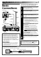
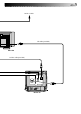
INSTALLING YOUR NEW RECORDER Aerial terminal Back of TV TV Aerial Cable 1 2 3 RF Cable (provided) 21-pin SCART Cable AV1 IN/OUT AV1 OUT switch Rear view AV1 OUTPUT SIGNAL SELECTION ● Set your TV to the VIDEO (or AV), Y/C, or RGB mode according to the type of your TV's SCART connector. ● For switching the TV's mode, refer to the instruction manual of your television. Make sure the package contains all of the accessories listed in “Specifications” (Z pg. 63).
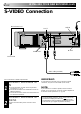
EN INSTALLING YOUR NEW RECORDER (cont.) S-VIDEO Connection Mains Power Cord ANT.IN S OUT AV1 IN S OUT AUDIO IN AV1 IN/OUT OUT L L R R AV2 IN/DECODER COMP. RF OUT OUT Y/C ANT.IN PAUSE/ R.A.EDIT RF OUT AUDIO OUT Mains outlet Audio cable (provided) For TV sets with an S-VIDEO input terminal: 1 2 CONNECT RECORDER TO TV a– Connect the aerial, recorder and TV as per "Basic Connections" ( Z pg. 3). b– Connect the recorder's S OUT terminal to the TV's SVIDEO IN terminal.
EN Aerial or Cable RF Cable (provided) Rear view S-Video cable (provided) Back of TV 5
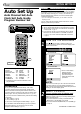
EN INITIAL SETTINGS Auto Set Up Auto Channel Set/Auto Clock Set/Auto Guide Program Number Set 8 • • • • • • • • • • • • • • • • • • • • • • When the button on the recorder/remote control is pressed for the first time to power on the recorder after you plug the mains power cord into a mains outlet, the Country Set display will appear on the TV screen and the recorder's front display panel.
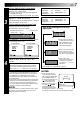
EN If you are referring to the on-screen display Press PUSH JOG%fi to move the highlight bar (pointer) to your country's name. ● If you have selected a country other than BELGIUM or SUISSE, go to step 4. ● If you have selected BELGIUM or SUISSE, go to step 3. 3 SELECT LANGUAGE Press OK. the Language Set display appears on the front display panel and/or on the screen.
EN INITIAL SETTINGS (cont.) If both auto channel set and auto clock set have been performed successfully: 1 Perform "Video Channel Set" on page 10. 2 Turn on the TV and select its VIDEO channel or AV mode, then make sure that all necessary stations have been stored in the recorder's memory by using the TV PROG button(s). ● If station names (ID — Z pg.
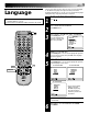
EN This recorder offers you the choice to view on-screen messages in 10 different languages. Though Auto Set Up selects the language automatically (Z pg. 8), you can change the language setting manually using this procedure as required. Language ● Be sure to set your Video Channel before performing Language setting (Z pg. 10). ● Turn on the TV and select the VIDEO channel (or AV mode). 2 1 2 3 4 5 6 7 8 9 0 1 1 2 3 TURN ON THE RECORDER Press . ACCESS MAIN MENU Press MENU twice.
EN INITIAL SETTINGS (cont.) If you have connected the video recorder to your TV via the provided RF cable only (RF connection) – Go to "With RF Connection" below. Video Channel Set Video Channel (RF Output Channel) is the channel on which your TV receives picture and sound signals from the video recorder through the RF cable.
EN 11 IMPORTANT: Before performing the following steps, make sure the recorder's power is off and there is no cassette inserted in the recorder. 8 • • • • • • • • • • • With AV Or S-VIDEO Connection • • • P • O • • • • ST • • • 1 2 2 1 2 3 4 5 6 7 8 9 0 3 3 Hold down STOP on the recorder until the display panel shows the following. SET VIDEO CHANNEL Press TV PROG – until the display panel shows "–OUT– –". ● Now the video channel is set to off.
EN INITIAL SETTINGS (cont.) With SHOW VIEW , timer programming is greatly simplified because each TV programme has a corresponding code number which your recorder is able to recognise. SHOWVIEW Setup NOTE: “Guide Program (GUIDE PROG) Number” refers to the assigned TV station numbers, according to broadcast area, for SHOW VIEW timer recording. Turn on the TV and select the VIDEO channel (or AV mode).
EN 4 5 4 ENTER SHOWVIEW NUMBER Press OK, and a cursor GUIDE PROG SET appears above “GUIDE 1 2 3 4 5 PROG”. Then, using the NUMBER keys, input the GUIDE PROG TV PROG SHOW VIEW number (found 1 1 in most TV listings) of a program scheduled to be broadcast on each station [0-9] = [MENU] : EXIT on the list from step 1, starting at the top. If you When entering a SHOWVIEW enter the wrong number, number for ZDF press CANCEL to backspace and input the correct number.
EN PLAYBACK The easiest, most basic operation possible with your video recorder is tape playback. Already-recorded signals on a video tape are read by your video recorder and displayed on your TV just like a TV programme. Basic Playback EC EJ P/ O ST PLAY TIME SCAN SHUTTLE ● Turn on the TV and select the VIDEO channel (or AV mode). ● Set the PAL/MESECAM switch to the appropriate position. Z pg.
EN Take advantage of special functions possible with the recorder’s controls or the remote control. Playback Features TIME SCAN SHUTTLE PLAY PAUSE Still Picture/Frame-By-Frame Playback 1 8 • • • • • • • • • • • • • • • FF RE JOG • • • • W • • • 2 0 15 4 PAUSE DURING PLAYBACK Press PAUSE. If there is vertical jitter, use the TV PROG buttons to correct the picture. ● During still picture, the sound from the previous 3 seconds (approx.
EN PLAYBACK (cont.) Manual Tracking Your video recorder is equipped with automatic tracking control. During playback, you can override this and adjust the tracking manually by pressing the TV PROG buttons. 8 • • • • • • • • • • • • • • • W RE FF • • • • PAL/MESECAM • • • REVIEW 2 1 2 3 4 5 6 7 8 9 0 4 TV PROG OVERRIDE AUTOMATIC TRACKING 1 Press SP/LP ( tracking. 2 Press TV PROG + or – to adjust tracking.
EN Index Search Instant ReView Your recorder automatically marks index codes at the beginning of each recording. This function gives you quick access to any one of 9 index codes in either direction. £ 2 Before starting, make sure that the recorder is off and that the Timer mode is disengaged. Before starting, make sure the recorder is in the Stop mode. ACTIVATE INDEX SEARCH fi % Press PUSH JOG or (™ or £). “™ 1” or “£ 1” is displayed on screen and search begins in the corresponding direction.
EN PLAYBACK (cont.) SpatializerW P SP O AT ST IA L IZ E R This feature expands sound field when you play back any stereo source or view a stereo programme while recording it. *SpatializerW has no effect on recording quality. 8 • • • • • • • • • • • • • • • • 1 • • • RE C. MEMORY A/B CODE 2 1 2 3 4 5 6 7 8 9 0 C.RESET 4 Press SPATIALIZER; the current setting will be displayed on the screen for about 5 seconds.
EN 19 Scene Finder Remote A/B Code Switching This function helps you check contents of unlabeled recorded tapes at the touch of a single button. The remote control is capable of controlling two JVC video recorders independently; one set to respond to the remote control’s A code control signals and another set to respond to B code control signals. The remote control is preset to send A code signals because your video recorder is initially set to respond to A code signals.
EN PLAYBACK (cont.) Your recorder is equipped with the TimeScan function. TimeScan allows noise free pictures to be displayed on your TV screen in the forward and reverse search modes. Audio will be played back at normal speed during any of the TimeScan modes (Z pg. 21). TimeScan allows you to view a program in search mode while listening to the audio.
EN 21 TimeScan Names of special-effects playback Speed SP Speed LP Audio output Reverse Forward Search Play Slow-Motion *Still -9x -7x -5x -3x -1x -1/6x -1/18x 0 1/18x -1/6x -1/18x 0 1/18x Audio is not output. Audio is output. -7x -3x Audio is output. Slow-Motion Play Search 1/6x 1x 2x 3x 5x 7x 9x 1/6x 1x 2x Audio is not output. 5x 9x Audio is output. * Still mode cannot be engaged using the remote control's PUSH JOG button.
EN PLAYBACK (cont.) TimeScan Audio The audio output can be set ON/OFF during TimeScan. Select ON/OFF as required. * The default setting is "ON". 2 1 2 3 4 5 6 7 8 9 0 1 4 2 3 MENU PUSH JOG 1 ACCESS MAIN MENU SCREEN Press MENU twice. ACCESS MODE SET SCREEN Move the highlight bar (pointer) to "MODE SET" by pressing PUSH JOG %fi, then press OK. MAIN MENU MODE SET AUTO CH SET MANUAL CH SET GUIDE PROG SET CLOCK SET JLIP ID NO. SET R.A.
RECORDING EN TV signals being received by the recorder’s built-in tuner can be recorded onto a video tape. You can “capture” a TV programme using your video recorder. Basic Recording TV PROG PLAY PAUSE ● Turn on the TV and select the VIDEO channel (or AV mode). ● Set the PAL/MESECAM switch to the appropriate position. Z pg.
EN RECORDING (cont.) Record One Programme While Watching Another Recording Features If your recorder is connected to the TV via AV connection, . . . . . . press TV/VCR. The recorder's VCR indicator and the TV broadcast being recorded disappear.
EN S-VHS (Super VHS) and VHS Your recorder can record in either S-VHS or VHS. To record in S-VHS; ● insert a cassette marked "S-VHS", the "S" (S-VHS) indicator will light on the display panel. ● then, perform the steps 1 – 4 below to set the "S-VHS" to "AUTO". The S-VHS recording mode will be selected. To record in VHS; ● insert a cassette marked "VHS". The VHS recording mode will be automatically selected regardless of the S-VHS mode setting.
EN Hi-Fi Audio Recording LEVEL Control PLAY PAUSE RECORDING (cont.) In most cases, setting the Hi-Fi audio recording level control to the center position will provide satisfactory results. If necessary, you can adjust the Hi-Fi audio recording level more precisely by reffering to the audio level indicator on the front panel. 8 • • • • • • • • 1 JOG • • • FF • • • W • RE • • • • Hi-Fi REC LEVEL • • • ADJUST AUDIO RECORDING LEVEL Turn Hi-Fi REC LEVEL in either direction.
EN You can choose whether or not to have various operational indicators appear on screen, by setting this function ON or OFF. Messages appear in the selected language (Z pg. 8 or 9). On-Screen Displays 1 Turn on the TV and select the VIDEO channel (or AV mode). 2 2 1 2 3 4 5 6 7 8 9 3 0 4 4 Press . ACCESS MAIN MENU SCREEN Press MENU twice. ACCESS MODE SET SCREEN Move the highlight bar (pointer) to "MODE SET" by pressing PUSH JOG %fi, then press OK.
EN TIMER RECORDING During SHOW VIEW and regular timer programming, the IllumiGuide feature tells you which button on the remote control must be pressed next by lighting it up. To use this feature, with the TV/SAT/VCR switch set to "VCR", press ILLUMI GUIDE before performing step 1. (PROG, REW, PLAY, FF light up at this time.) SHOWVIEW Timer Recording If you aren't going to use the Illumi-Guide feature, go directly to step 1.
EN 3 NOTE: ACCESS SHOWVIEW PROGRAM SCREEN Press OK, and the SHOW VIEW Program screen appears (if you’re just starting out, “P1” appears). – P1 – SHOWVIEW 123456789 START STOP 21:00 = 22:00 The display panel shows the programme start time. Pressing PROG CHECK changes the display to the programme stop time, then the date and channel position. 29 SP ON DATE 25.12 TV PROG 1 ARD : OK SP To Delay The Stop Time . . . . . . press ADD TIME (NUMBER Key "5") after pressing OK in step 3.
EN TIMER RECORDING(cont.) Regular Timer Programming If you don’t know the S HOWVIEW number for the programme you wish to record, use the following procedure to set your recorder to timer-record the programme. Or you can use the Illumi-Guide feature, where the remote control tells you which button to press next by lighting it up. To use the Illumi-Guide feature, with the TV/SAT/VCR switch set to "VCR", press ILLUMI GUIDE before performing step 1. (PROG, REW, PLAY, FF light up at this time.
EN 8 • • • • • • • • • • • • • • • • • • • 6 TIMER • • • 5 31 ENTER PROGRAMME DATE Press DATE +/–. (The current date appears on screen. The date you enter appears in its place.) ● If you are using the Illumi-Guide feature, the following buttons remain lit: START +/–, STOP +/–, DATE +/–, TV PROG +/– and MENU. ENTER CHANNEL POSITION Press TV PROG +/–. – P1 – START 21:00 SP DATE 25.
EN TIMER RECORDING (cont.) Auto Timer When the Auto Timer is set to ON the timer is automatically engaged when the recorder power is turned off and automatically disengaged when the recorder is powered back on. 2 1 2 3 4 5 6 7 8 9 1 0 CANCEL TIMER 4 TV PROG+/– START+/– D 2 /– E+ STOP+/– AT 3 MENU 1 Press MENU twice. ACCESS MODE SET SCREEN Press PUSH JOG %fi to move the highlight bar (pointer) to "MODE SET", then press OK.
EN 33 Auto SP/LP Timer 8 • • • • • • • • • • • • • • • • • • • AUTO SP/LP TIMER indicator AU TO SP /L P TI M ER • • • If, when recording in SP mode, there is not enough tape to record the entire programme, the recorder automatically switches to LP mode to allow complete recording. 1 ENGAGE AUTO SP/LP TIMER Press AUTO SP/LP TIMER on the recorder front panel. The AUTO SP/LP TIMER indicator lights up. For Example . . .
EN EDITING Editing Mode Setting Preparation For Editing You can minimize picture degradation while editing. ● Turn on the TV and select the VIDEO channel (or AV mode). ● Set the PAL/MESECAM switch to the appropriate position. Z pg. 16 8 • • • • • • • • • • • • • • • • 2 Press MENU twice. ACCESS MODE SET SCREEN Move the highlight bar (pointer) to "MODE SET" by pressing PUSH JOG %fi, then press OK.
EN 35 To Select The External Input Mode To record external audio and video signals; 1 Press the remote control's NUMBER key "0". 2 Press AV/S SELECT on the front of the recorder to select the appropriate external input mode.
EN EDITING (cont.) You can use your video recorder as the source player or the recording deck. Edit To Or From Another 1 Video Recorder . 2 2 2 3 4 5 6 7 8 9 0 PL AY 4 RECORD 3 1 Connect the player’s 21-pin SCART (AV) connector to the recorder’s 21-pin SCART (AV) connector as illustrated on page 37. When Using Your Video Recorder As The Source Player . . . . . . connect its AV1 IN/OUT connector to the recording deck. When Using Your Video Recorder As The Recording Deck . . . . . .
EN TV Receiver Player Your recorder 21-pin SCART Cable (not provided) VIDEO CHANNEL or AV mode Recorder Your recorder RF Cable (provided) VIDEO CHANNEL or AV mode Another recorder Another recorder Recorder TV Receiver RF Cable (provided) 21-pin SCART Cable (not provided) 37 Player For Customers in Australia and New Zealand: When connecting the AV cable, use the input and/or output cable adapter as illustrated below.
EN EDITING (cont.) You can use a camcorder as the source player and your video recorder as the recorder. Edit From A Camcorder 1 Set the PAL/MESECAM switch to the appropriate position. Z pg. 16 2 1 2 3 4 5 6 7 8 9 0 NUMBER "0" 2 4 TV PROG 3 3 4 1 5 MAKE CONNECTIONS Connect the camcorder’s AUDIO/VIDEO OUT connectors to the recorder’s front panel AUDIO/VIDEO input connectors.
EN PLAY A. DUB Audio Dubbing 39 Audio dubbing replaces the normal audio sound of a previously recorded tape with a new soundtrack. Normal audio track Pre-recorded tape Video/Hi-Fi audio track 8 Audio-dubbed tape • • • • • • • • • • • • • • • PA STOP • • • • U SE • • • 1 CD Player etc. 2 CD Player etc.
EN EDITING (cont.) Insert Editing Set the PAL/MESECAM switch to the appropriate position. Z pg. 16 Recorder Insert editing replaces part of the recorded scene with new material. Both the picture and Hi-Fi audio soundtrack are replaced with new ones, while the normal audio soundtrack remains unchanged. If you wish to change the normal audio track as well, use the audio dubbing function simultaneously. Use your video recorder as the recorder.
PLAY INSERT EN 8 • • • • • • • • • • • • • • • • • • • A. DUB • • • 6 7 ENGAGE INSERT EDITING Press INSERT. ● Your recorder enters the Insert-Pause mode. (" ", " and " " light up on the front display panel.) ● The TV screen changes from the still picture to the input source you are going to record. 8 2 2 3 4 5 6 7 8 9 0 Load the source cassette and play back the segment that is to be inserted.
EN EDITING (cont.) Random Assemble Editing Set the PAL/MESECAM switch to the appropriate position. Z pg. 16 This function makes it easier to create edited videos when your video recorder is used as the source player in combination with another JVC video recorder equipped with a Remote PAUSE Connector. You can pre-program up to 8 scenes or “cuts” for automatic editing in the sequence you have specified. You can also perform Random Assemble Editing with a second non-JVC recorder. Z pg. 43 1 PAUSE/ R.
EN Find the point on the source tape from where you want the edited scene to begin by pressing PUSH JOG or using the TIME SCAN SHUTTLE ring or the JOG dial, then press IN/OUT. =1 2 3 4 5 6 7 8 % fi 8 LOCATE EDIT-IN POINT 0:00:00 (+) 0:00:00 ● The edit-in point is [MENU] : EXIT registered in memory and appears on the screen.
EN INFORMATION ON J TERMINAL J Terminal (JLIP(Joint Level Interface Protocol) Connector) 8 • • • • • • • • • • • • • • • • • • • The J Terminal is used to connect the recorder to a personal computer or similar device to allow computerized control of the recorder during editing and certain other operations. Examples: • • • ● Enables Random Assemble Editing of up to 99 segments with the optional JLIP PLAYER PACK HS-V1EG, using this recorder as the playback unit.
SYSTEM CONNECTIONS EN Connecting/ Using A Decoder TV Receiver RF Cable (provided) TV Aerial Cable 45 The AV2 IN/DECODER connector can be used as an input terminal for an external decoder (descrambler). Simply connect a decoder and you can enjoy the variety of programming that is available through scrambled channels. 1 2 3 SELECT INPUT MODE Set "AV2 SELECT" to "DECODER". (Z pg.
EN SYSTEM CONNECTIONS (cont.) Connecting/ Using A Stereo System These instructions enable you to connect your video recorder to your Hi-Fi stereo system (if you have one) and listen to the soundtrack through the stereo. Aerial or Cable Mains outlet ANT. IN AV1 IN/OUT AV1 IN S OUT AUDIO IN AV1 IN/OUT OUT L L R R AV2 IN/DECODER COMP. OUT Y/C RF OUT ANT.IN PAUSE/ R.A.
EN FM Tuner CD Player Stereo Amplifier AUX IN or TAPE MONITOR I I I I I I I I I I I I I I I I I I I I I I I I I I I I I I I I I I I I I I I I I I I AUDIO OUT Television Speaker For customers in Australia and New Zealand: When connecting the AV cable to your TV, use the input and output cable adapters.
EN SPECIAL FEATURES Your remote control can operate the basic functions of your TV set. In addition to JVC TVs, other manufacturer’s TVs can also be controlled by setting the appropriate switch on the remote control. Before you start . . . ● Turn on the TV using its remote control. ● Set the remote control’s TV/SAT/VCR switch to TV. TV MultiBrand Remote Control 1 DISPLAY 2 NUMBER 1 2 3 4 5 6 7 8 9 2 0 4 TV PROG TV/SAT/VCR CR /V 3 1 Refer to the chart below.
EN Satellite Tuner MultiBrand Remote Control Your remote control can operate the basic functions of your satellite tuner set. In addition to JVC satellite tuners, other manufacturer’s satellite tuners can also be controlled by setting the appropriate switch on the remote control. Before you start . . . ● Turn on the satellite tuner using its remote control. ● Set the remote control’s TV/SAT/VCR switch to SAT.
EN TUNER SET Turn on the TV and select the VIDEO channel (or AV mode). IMPORTANT Perform the following steps only if auto channel set has not been set correctly by Auto Set Up function (Z pg. 6) or if you have moved to a different area or if a new station starts broadcasting in your area. Your recorder needs to memorise all necessary stations in channel positions in order to record TV programmes.
EN 5 2 1 2 3 4 5 6 7 8 9 0 1 PERFORM AUTO CHANNEL SET Press PUSH JOG%fi to move the highlight bar (pointer) to the language of your choice , then press OK to initiate Auto Channel Set. AUTO SET PLEASE WAIT 0 + + + ● The Auto Set screen [MENU] : EXIT appears, and End remains on screen Beginning while the recorder searches for receivable stations. As Auto Channel Set progresses, the " " mark on the screen moves from left to right. Wait until the screen as shown in step 6 appears.
EN TUNER SET (cont.) Press MENU twice. ACCESS CONFIRMATION SCREEN Press PUSH JOG%fi to move the highlight bar (pointer) to “MANUAL CH SET”, then press OK. The Confirmation screen appears. 1 2 SELECT POSITION Press PUSH JOG%fi until an open position in which you want to store a channel begins blinking, then press OK. The Manual Ch. Set screen appears. % INPUT CHANNEL The number "01" appears blinking beneath "CH". Press the NUMBER keys to input the channel number you want to store.
EN Fine-Tuning Channels Already Stored Set Stations (A) 4 % Press PUSH JOG%fi until the item you want begins blinking. Then press OK twice and the station’s name (ID) begins blinking. Press PUSH JOG%fi until the new station’s name (ID) you want to store begins blinking. Registered station names (Z pg. 54) appear as you press PUSH JOG%fi. SWITCH STATIONS Press OK. ● Repeat steps 1 through 3 as necessary. CLOSE CONFIRMATION SCREEN Press MENU. 4 NOTE: First perform step 1 of the above procedure.
EN TUNER SET (cont.
CLOCK SET EN Turn on the TV and select the VIDEO channel (or AV mode). 55 IMPORTANT Perform the following steps only if auto clock set has not been set correctly by Auto Set Up function (Z pg. 6) or Auto Channel Set (Z pg. 50) or if the recorder's memory backup has expired. If you performed Auto Set Up or Auto Channel Set without ever having set the clock previously, the recorder’s built-in clock is also set automatically. The Auto and Manual clock setting procedures are necessary when . . .
EN CLOCK SET (cont.) Auto Clock Set 1 2 3 4 5 6 7 8 9 0 1 AUTO CLOCK PLEASE WAIT JUST CLOCK : OFF ● If "TV PR." isn't set to the TV. PR : 1 channel position on which Auto Clock data is received, "ERROR" appears, and then the screen from step 3 reappears. To set "TV PR.", press OK to place the pointer next to it, then cycle through the numbers by pressing PUSH JOG%fi until the number representing the channel position in which the station transmitting clock setting data is stored appears.
TROUBLESHOOTING EN 57 Before requesting service for a problem, use this chart and see if you can repair the trouble yourself. Small problems are often easily corrected, and this can save you the trouble of sending your video recorder off for repair. POWER SYMPTOM POSSIBLE CAUSE CORRECTIVE ACTION 1. No power is applied to the recorder. ● The mains power cord is disconnected. Connect the mains power cord. 2. The clock is functioning properly, but the recorder cannot be powered.
EN TROUBLESHOOTING (cont.) 4. Camcorder recording is not possible. ● The camcorder has not been properly connected. ● The input mode is not correct. Confirm that the camcorder is properly connected. Set the input mode to “AU”. TIMER RECORDING SYMPTOM POSSIBLE CAUSE CORRECTIVE ACTION 1. Timer recording won’t work. ● The clock and/or the timer have been set incorrectly. ● The timer is not engaged. Re-perform the clock and/or timer settings.
QUESTIONS AND ANSWERS EN 59 PLAYBACK RECORDING Q. What happens if the end of the tape is reached during playback or search? A. The tape is automatically rewound to the beginning. Q. When I pause and then resume a recording, the end of the recording before the pause is overlapped by the beginning of the continuation of recording. Why does this happen? A. This is normal. It reduces distortion at the pause and resume points.
EN INDEX FRONT VIEW 1 23 45 6 7 8 9 0 !@ # REW S LO W 8 SLOW FF R.A.EDIT IN/OUT START A.DUB INSERT SPATIALIZER TIMER HEAD PHONE VOLUME • • • • • • 0• • • • Hi-Fi REC LEVEL • • • • • • AV/S SELECT PAL MESECAM • • • AUTO SP/LP • 10 0 • • 10 VIDEO (MONO)L–AUDIO–R +8 4 0 TIMER JLIP L $ % ^ 6 10 –20dB NORM &*() q w M SP LP R REVIEW SP/LP VCR REMAIN e TV PROG/ JOG SHUTTLE rt y u i o Open the lid to access covered connectors and buttons. 1 STANDBY/ON Button Z pg.
EN 61 REAR VIEW 23 1 4 5 AV1 IN S OUT AUDIO IN AV1 IN/OUT OUT L L R R AV2 IN/DECODER 78 1 2 3 4 5 6 9 Mains Power Cord Z pg. 3 S-Video IN Connector Z pg. 36 S-Video OUT Connector Z pg. 4 AV1 IN/OUT Connector Z pg. 3, 36 AV1 OUT Switch Z pg. 3 ANT. IN Connector Z pg. 3 COMP. 6 RF OUT OUT ANT.IN Y/C PAUSE/ R.A.EDIT 0 ! AUDIO IN (L/R) Connectors Z pg. 46 AUDIO OUT (L/R) Connectors Z pg. 46 AV2 IN/DECODER Connector Z pg. 36, 45 Remote PAUSE Connector Z pg. 38 R.A.EDIT Connector Z pg.
EN INDEX (cont.) REMOTE CONTROL C.MEMORY DISPLAY 1 2 2 3 ADD TIME 5 6 DAILY WEEKLY 9 4 7 8 C.RESET AUX CANCEL 0 START STOP TIMER 4 TV PROG DATE EXPRESS PROGRAMMING AUDIO MONITOR TV/VCR TV N E FIN DER PROG C HEC K /MENU ROG TV 1P 3 VOL. OK PUSH JOG I L L U MI G U I D E MULTI BRAND REMOTE CONTROL UNIT E R Buttons with a small dot on the left side of the name can also be used to operate your TV with the TV/ SAT/VCR switch set to "TV". Z pg.
SPECIFICATIONS GENERAL Power requirement Power consumption : AC 220 – 240 V`, 50/60 Hz : 27 W (HR-S9400E) 29 W (HR-S9400EH) Temperature Operating : Storage : Operating position : Dimensions (WxHxD) : Weight : Format : Maximum recording time (SP) : (LP) VIDEO/AUDIO Signal system Recording system Signal-to-noise ratio Horizontal resolution Frequency range Input/Output 5°C to 40°C –20°C to 60°C Horizontal only 465 x 105 x 353 mm 5.6 kg S-VHS/VHS PAL standard 240 min. with E-240 video cassette : 480 min.
EN The Auto Set Up function sets the tuner channels, clock and Guide Program numbers automatically. BEFORE YOU START PLEASE MAKE SURE THAT: n n n n The TV aerial cable is connected to the ANT.IN jack on the rear panel of the video recorder. The video recorder's mains power cord is connected to a mains outlet. The video recorder is turned off. Load batteries into the remote control. 1 Press 2 Press PUSH JOG %fi (remote) to select the international telephone country code. (recorder/remote). (Ex.