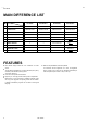
HV- 29LPZ SERVICE MANUAL COLOUR TELEVISION HV-29LPZ HV-29LPZ/HK HV-29LPZ/-A HV-29LPZ/EE BASIC CHASSIS MF CONTENTS ! ! ! ! ! 1 SPECIFICATIONS ・・・・・・・・・・・・・・・・・・・・ 2 SAFETY PRECAUTIONS ・・・・・・・・・・・・・・3 ・・・・・・・・・・・・・・ MAIN DIFFERENCE LIST ・・・・・・・・・・・・・・4 ・・・・・・・・・・・・・・ FEATURES・・・・・・・・・・・・・・・・・・・・・・・・・・ ・・・・・・・・・・・・・・・・・・・・・・・・・・ 4 FUNCTIONS ・・・・・・・・・・・・・・・・・・・・・・・・・ 6 ! ! ! ★ ★ SPECIFIC SERVICE INSTRUCTIONS ・・・・ 8 SERVICE ADJUSTMENTS・・・・・・・・・・・・ ・・・・・・・・・・・・ 14 PARTS LIST ・・・・・・・・・・・・・・・・・・・・・・・ 37 OP
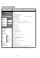
HV- 29LPZ SPECIFICATIONS Item Content Dimensions ( W× ×H× ×D ) 73.2cm×58.7c m× 51.8cm Mass 48.0kg TV RF System B/G, I, D/K, K1, M Colour System PAL / SECAM / NTSC 3.58 / NTSC 4.43 Stereo System A2 (B/G) / NICAM (B/G, I, D/K, K1) Teletext System Fastext (UK system) * WST(world s tandard Texst) [ * Without TEXT mode : HV-29LPZ/HK ] VL 46.25MHz ~ 168.25MHz Receiving Frequency VH 175.25MHz ~ 463.25MHz UHF CATV 471.25MHz ~ 863.
HV- 29LPZ SAFETY PRECAUTIONS 1. The design of this product contains special hardware, many circuits and components specially for safety purposes. For continued protection, no changes should be made to the original design unless authorized in writing by the manufacturer. Replacement parts must be identic al to thos e used in the original circuits. Service should be performed by qualified pers onnel only. 2. Alterations of the design or circuitry of the products should not be made.
HV- 29LPZ MAIN DIFFERENCE LIST Model name HV- 29LPZ HV- 29LPZ /HK HV- 29LPZ /-A HV- 29LPZ/EE MICOM PWB SMF0M901A-H2 SMF0M902A-H2 SMF0M903A-H2 SMF0M904A-H2 ! POWER CORD QMP40D0-200J5 QMPN050-200-E2 QMPR010-200-E2 QMP40D0-200J5 ! FRONT CABI.
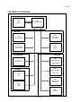
HV- 29LPZ SYSTEM BLOCK DIAGRAM MICOM PWB IC 004 MEMORY IC 001 MICRO COMPUTER SDA 0 SCL 0 SDA 2 SCL 2 SDA 1 SCL 1 MAIN PWB IC 701 BBE CONTROL IC 301 DEF & RGB PROCESSOR IC 101 MULTI SOUND PROCESSOR TU0 01 TUNER SYNC SEP PWB 100Hz PWB IC 101 VIDEO PROCESS & CODEC MAIN IC 301 SYNC SEP PWB IC 151 VIDEO PROCESS & CODEC SUB AV SW PWB IC 101 SW IC 201 SAMPLE RATE CONVERTER TU0 01 TUNER IC 301 ENHANCE No.
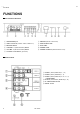
HV- 29LPZ FUNCTIONS ■ Front Terminal & Control 1 HEADPHONE jack 2 VIDEO-4 terminal (S-VIDEO / VIDEO / L/MONO / R) 3 MENU/OK Button 4 CHANNEL -/+ (MENU UP/DOWN) Button 5 VOLUME -/+ (MENU LEFT/RIGHT) Button 6 TV/VIDEO / EXIT Button (Input s elect) 7 SENSOR (Remote Control & ECO) 8 SPATIALIZER LAMP 9 ECO LAMP A POWER LAMP B POWER SW Button (MAIN POWER on and off) ■ Rear Terminal 1VIDEO-1 (INPUT) terminal (S, V, L, R) 2 VIDEO-2 (INPUT) terminal (V, L, R) 3 VIDEO-3 (INPUT) terminal (V/Y, Cb, Cr, L, R) / COM
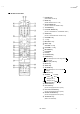
HV- 29LPZ ■ Remote Control Unit 1 POWER Key (SUB POWER on and off) 2 BASS Key (SUPER BASS function on or off) 3 SPATIALIZER Key (Choos e a mode LIVE→MONO→OFF) 4TV/VIDEO Key 5PICTURE MODE Key (Choos e a mode BRIGHT →STANDARD→ SOFT) 6 ZOOM Key (Choos e a mode REGULAR→ZOOM →16:9) 7CHANNEL Key 8 -/-- Key 9 RETURN + Key AMULTI Key B VOLUME +/- Key CCHANNEL +/- Key D MUTING Key E PIP MODE FPIP Key G POSITION Key HFREEZE Key View the MAIN picture’s frozen image as the SUB-PICTURE.
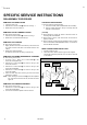
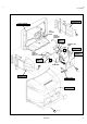
HV- 29LPZ SPECIFIC SERVICE INSTRUCTIONS DISASSEMBLY PROCEDURE REMOVING THE REAR COVER CHECKING THE PW BOARD 1. Unplug the power c ord. 2. Remove the 16 screws marked ! as shown in the Fig. 1. 3. Withdraw the rear cover toward you. To check the back side of the PW Board. 1) Pull out the chassis . (Refer to REMOVING THE CHASSIS). 2) Erect the c hassis vertically so that you c an easily check the back side of the PW Board.
HV- 29LPZ DOME SPEAKER BOX FRONT CABINET CRT SOCKET PWB FRONT CONT ROL PWB (2/2) C CONT ROL BASE MICOM PWB POWER & DEF PWB CLAW 100Hz PWB AV TERMINAL FRONT CONT ROL PWB (1/2) CONT ROL BASE MAIN PWB CHASSIS BLK PWB CLAW AV SW PWB C B (×5) DOME SPEAKER BOX POWER CORD REAR COVER A (×15) Fig. 1 No.
HV- 29LPZ REMOVING THE CRT ∗ Replacement of the CRT should be performed by 2 or more pers ons. • After removing the c over, chassis etc., 1. Putting the CRT c hange table on soft cloth, the CRT change table should also be c overed with s uch soft cloth (shown in Fig.3). 2. While keeping the s urfac e of CRT down, mount the TV s et on the CRT change table balanced will as shown in Fig.4. 3. Remove 4 sc rews marked by arrows with a box type screw driver as s hown in Fig.4.
HV- 29LPZ REPLACEMENT OF MEMORY ICs 1. Memory ICs This TV us e memory ICs. In the memory ICs, there are memorized data for correctly operating the video and deflection circuits . When replacing memory ICs, be s ure to us e ICs written with the initial values of data. S E RV ICE M EN U 2. Procedure for replacing memory ICs 1. IF 3. AUDIO 5. VSM PRESET 7. PIP 9. SHIPPING(OFF) (1) Power off Switch the power off and unplug the power cord from the wall outlet. (2) Replace ICs.
HV- 29LPZ SETTING VALUES OF SYSTEM CONSTANT SET (TABLE 1) MODEL No. Setting item HV- 29LPZ HV- 29LPZ/-A HV- 29LPZ/HK HV- 29LPZ/EE 1. TEXT YES YES NO YES 2. BLUE BACK MUTE NO YES NO ← 3. E. M. C NO ← ← ← 4. WHITE BACK NO ← ← ← 5. COLOUR AUTO NO YES NO ← 6. PICTURE TILT YES ← ← ← SERVICE MENU SETTING ITEMS (TABLE 2) Setting item 1. IF Setting value 1. VCO 2. ATT ON / OFF Setting item 5. VSM PRESET BRIGHT STANDARD SOFT 2. V / C 1. RGB BLK 2. WDR R 3. WDR G 4. WDR B 5.
HV- 29LPZ USER SETTING VALUES (TABLE 3) Setting item Setting value Setting item Setting value MAIN POWER SW OFF SUB POWER ON SHIPPING CHANNEL PR1 DISPLAY INDICATED PRESET CHANNEL See ; OPERATING INSTRUCT IONS.
HV- 29LPZ SERVICE ADJUSTMENTS BEFORE STARTING SERVICE ADJUSTMENT 1. There ar e 2 ways of adjusting this TV: One is with the REMOTE CONTROL UNIT and the other is the conventional method using adjustment parts and components. 2. The setting (adjustment) using the REMOTE CONTROL UNIT is made on the basis of th e initial setting values. The setting values which adjust the screen to the optimum condition can be differ ent fr om the initial setting values. 3.
HV- 29LPZ ADJUSTMENT LOCATIONS FRONT CONTROL PWB (1/2) PO WER SW PO WER FRON T ECO SPET IA LI ZE R F 90 1 FRONT CONTROL PWB (2/2) T V/VID EO EXT VO L UP VO L DO WN CD S R4 M ENU / OK CH DO WN CH UP J W L4 V4 S IN IN (V IDEO -4 ) HEA D PHO NE FRON T J F C9 0 1 PW CN 00 2 L F 90 1 Po w er c o rd T o AV SW P WB MAIN PWB POWER&DEF PWB CN 11 1 FRON T CN 00 2 W FRON T DEG R3 Sp e ak er MICOM P WB CN 00 4 CN 00 7 CN 00 5 AV SW PWB 10 0H z PWB T UN ER 2 HV CN 00 6 B LK P WB CN
HV- 29LPZ BASIC OPERATION SERVICE MENU 1. TOOL OF SERVICE MENU OPERATION Operate the SERVICE MENU with the REMOTE CONTROL UNIT. 2. SERVICE MENU ITEMS With the SERVICE MENU, various settings (adjustments) c an be made, and they are broadly c lassified in the following items of settings (adjus tments ): (1) 1. IF ・・・・・・・ ・・・・・・・・・・・・・ ・・・・・・・・・・ This mode adjusts the setting values of the IF circuit. (2) 2.V/C ・・・・・・・ ・・・・・・・・・・・・・ ・・・・・・・・・ This mode adjusts the setting values of the VIDEO / CHROMA circuit.
HV- 29LPZ 3. BASIC OPERATION OF SERVICE MENU (1) Ho w to enter SERVICE MENU Press the PICTURE MODE key and the DISPLAY key of the REMOTE CONTROL UNIT simultaneous ly, and the SERVICE MENU sc reen of Fig. 1 will be dis played. SERVICE MENU S E RV ICE M EN U 1. IF 3. AUDIO 5. VSM PRESET 7. PIP 9. SHIPPING(OFF) (2) Selection of SUB MENU SCREEN Press one of keys 1~ 0 of the REMOTE CONTROL UNIT and select the SERVICE MENU SCREEN (See Fig. 3), form the SERVICE MENU. SERVICE MENU → SUB MENU 1. 2. 3. 4. 5. 6. 7.
HV- 29LPZ SERVICE MENU SCREEN SERVICE MENU SERVICE MENU 1. I F 3. A UDI O 5. V S M PR ES E T 7. P IP 9. S HI PP I NG(OF F) 1-0 : S ELE CT 2. V /C 4. DE F 6. S TA T US 8. W B P RE SE T 0. B US F REE DI SP : EX IT SUB MENU 1. I F (CW) 5. VSM PRESET VSM PRESET B RIGH T STA N DA R D SOFT 1. 2. 3. 4. 5. C ONT. B RIGH T SH A RP C OLOUR TIN T 1. CONT - /+ OK STD *** : S TO RE DI SP : E XI T MA IN 1. V CO 2. A TT O N / OF F 1-2 : S ELE CT ***. .
HV- 29LPZ (3) Method of Setting " Method of Setting 1.IF [VCO] ・・・・・・・ ・・・・・・・・・・・・・ ・・・・・・・ * It must not adjust without signal ① 1 Key ・・・・・・・ ・・・・・・・・・・・・・ ・・・・・ Select 1.IF. ② 1 Key ・・・・・・・ ・・・・・・・・・・・・・ ・・・・ Select 1. VCO (CW) Check the arrow position between the ABOVE REF. and BELOW REF. ③ 2 Key ・・・・・・・ ・・・・・・・・・・・・・ ・・・・・ Select 2.ATT ON/OFF (Strong Elec tric Field : ON / Generally Electric Field : OFF) ④ DISPLAY(DISP) Key・・・・・・・ ・・・・・ Return to the SERVICE MENU screen. " Method of s etting 2.
HV- 29LPZ ADJUSTMENT CHECKING ITEM Item Measuring instrument Test point Ad justment part Description Check of B1 Power Supply Signal Generator TP-91(B1) 1. RGB BLK TP-E(# #) [X connector DC voltm eter on POWER DEF PWB] Remote Control unit 1. 2. 3. 4. 5. Check of High Voltage Signal Generator 1. 2. 3. 4. 5. CRT anode Receive any broadc ast. Press the ZOOM key and select the FULL mode. Select 2. V/C from the SERVICE MENU. Select 1. RGB BLK with function UP / DOWN key.
HV- 29LPZ ADJUSTMENT OF FOCUS & SCREEN Measuring instrument Item Ad justment of FOCUS Test point Signal gener ator Ad justment part Description FOCUS 1 VR(In HVT) 1. Receive a cross -hatc h signal. FOCUS 2 VR(In HVT) 2. Press the ZOOM key and select the regular mode. 3. By turning the FOCUS 1 VR, adjust the to make the vertical lines as fine and sharp as pos sible. 4.
HV- 29LPZ VSM PRESET SETTING Item Setting of VSM PRESET Measuring instrument Test point Remote control unit Ad justment part 1.CONT. 2. BRIGHT 3. SHARP 4. COLOUR 5. TINT Description 1. Select 5.VSM PRESET from the SERVICE MENU. 2. Select STD with the PICTURE MODE key of the remote control unit. 3. Adjust the function UP/DOWN and LEFT/RIGHT key to bring the set values of 1.CONT ~ 5. TINT to the values shown in the table. 4. Press the MENU/OK key and memorize the set value. 5.
HV- 29LPZ VIDEO/CHROMA CIRCUIT ADJUSTMENT The setting (adjustment) using the REMOTE CONTROL UNIT is made on the basis of the initial setting values. The setting values which adjust the scr een to the optimum condition can be different from the initial setting values. " marked Colour system Setting item Colour system Initial setting value PAL SECAM Setting item NT SC RGB BLK Initial setting value PAL 8.TINT 9.SHARP 3.WDR G 000 10.VCO ADJUSTMENT 4.WDR B % -010 11.VID AGC % 000 5.
HV- 29LPZ Measuring instrument Item Ad justment of SUB COLOURⅠ Ⅰ Test point Remote control unit Ad justment part Description 7.COLOUR (PAL/SECAM/NT SC) [Method of adjustm ent without m easuring instrument] PAL COLOUR (PAL COLOUR) 1. 2. 3. 4. Receive PAL broadcast. Select 2.V/C from the SERVICE MENU. Select 7.COLOUR with the function UP/DOWN key. Set the initial setting value for PAL COLOUR with the function LEFT/RIGHT key. 5.
HV- 29LPZ Measuring instrument Item Ad justment of SUB COLOUR Ⅱ Test point Signal gener ator TP-47B TP-E(# #) [CRT Oscilloscope SOCKET PWB ] Remote control unit Ad justment part Description 7.COLOUR (PAL/SECAM/NT SC) [Method of adjustm ent using measur ing instrument] PAL COLOUR (PAL COLOUR) 1. 2. 3. 4. 5. 6. 7. SECAM COLOUR (-) (A) W Cy Mg B Receive a PAL full field colour bar signal(75% white). Select 2.V/C from the SERVICE MENU. Select 7.COLOUR with the function UP/DOWN key.
HV- 29LPZ Measuring instrument Item Ad justment of SUB TINT Test point Remote control unit Ad justment part Description 8.TINT [Method of adjustm ent without m easuring instrument] NTSC 3.58 TINT (NTSC 3.58 TINT) 1. Input a NTSC 3.58MHz COMPOSITE VIDEO signal (full field colour bar with 75% white) from the EXT terminal. 2. Select 2.V/C from the SERVICE MENU. 3. Select 8.TINT with the function UP/DOWN key. 4. Set the initial s etting value of NTSC 3.58 TINT with the function LEFT/RIGHT key. 5.
HV- 29LPZ DEF. CIRCUIT ADJUSTMENT There are 3 aspect mod es ( ①REGULAR, ②ZOOM & ③ 16 : 9) of the adjustment ( 1 ) 100Hz i mode & ( 2 ) 60Hz p mode ・・・・・・ depending upon the kind of signals ( ver tical frequency 100Hzi / 60HZp). " " " When the 100Hz REGULAR mode has been established, the setting of other modes will be done autom atically. Ho wever, if the picture quality has not been optimized, adjust each mod e again, respectively.
HV- 29LPZ Item Ad justment of V-SHIFT Measuring instrument Test point Signal gener ator Ad justment part 1. V- SHIFT Description [REGULAR mode] 1. Receive a circle pattern signal of vertic al frequency 50Hz. 2. Select 4.DEF from the SERVICE MENU. 3. Select 1.V-SHIFT with the function UP/DOWN key. 4. Adjust V-SHIFT to make A = B. 5. Check the adjustment value above in other zoom mode. If it is a wrong adjustment, re-adjust in ZOOM mode and adjust by 1. V-SHIFT and 13.V-LIN. 6.
HV- 29LPZ Item Measuring instrument Test point Ad justment of Signal gener ator H. CENTER Ad justment part 3.H-CENT. 13. Receive a c ircle pattern s ignal. 14. Select 3.H-CENT and set the initial setting value. 15. Adjust H-CENT to make C=D. 16. Press the MENU/OK key and memorize the set value. Remote control unit C Description D Ad justment of H.SIZE 4.H-SIZE 17. Receive a cross-hatch signal. 18. Select 4.H-SIZE and set the initial setting value. 19.
HV- 29LPZ Item Ad justment of TRAPEZ Measuring instrument Test point Signal gener ator Remote control unit Ad justment part 5.TRAPEZ 26. Receive a cross-hatch signal. 27. Select 5.TRAPEZ with the function UP/DOWN key. 28. Set the initial setting value of TRAPEZ with the function LEFT/RIGHT key. 29. Adjust TRAPEZ and bring the VERTICAL lines at the right and left edges of the screen parallel. 30. Press the MENU/OK key and memorize the set value. 7.COR-PIN 31. Select 9.
HV- 29LPZ Item Ad justment of BOW Measuring instrument Signal gener ator Remote control unit Test point Ad justment part Description " In cas e where there is a bow-shaped distortion of images on the screen. (Fig.B) 11.BOW 42. Select 11.BOW with the function UP/DOWN key. 43. Adjust BOW, and bring the VERTICAL lines straight. 44. Press the MENU/OK key and memorize the set value. Fig. B Ad justment of V-S.CR & V.LIN. 12.V-S.CR 13.V.LIN.
HV- 29LPZ AUDIO CIRCUIT ADJUSTMENT " Do not touch 3. AUDIO adjustment of the SERVICE MENU as it requires no adjustment. If values had changed for the some reas on, set the initial values in the following table. 3. AUDIO(Do not adjust) Setting item 32 Variable range fixed value 1. ERR LIMIT 00H~FFH 10H 2. A2 ID THR 00H~FFH 14H 3. QUASI 00H~FFH ―――― No.
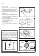
HV- 29LPZ PURITY, CONVERGENCE ADJUSTMENT PURITY ADJUSTMENT 1. Demagnetize CRT with the demagnetizer. WEDGE DYNAMIC CONVERGENCE ADJUSTMENT 2. Loosen the retainer screw of the deflec tion yoke. PURITY MAGNET(P) 3. Remove the wedges. CRT 4. Input a green raster signal from the signal generator, and turn the screen to green raster. 46 CRT SOCKET PWB P / C MAGNETS DEF. YOKE 5. Move the deflection yoke backward. 6. Bring the long lug of the purity magnets on the short lug and position them horizontally.
HV- 29LPZ STATIC CONVERGENCE ADJUSTMENT (FRONT VIEW) 1. Input a cross hatch signal. 2. Using 4-pole convergence magnets , overlap the red and blue lines in the center of the screen (Fig.1) and turn them to magenta (red/blue). 3. Using 6-pole convergence magnets, overlap the magenta (red/blue) and green lines in the c enter of the screen and turn them to white. Fig. 1 (FRONT VIEW) 4. Repeat 2 and 3 above, and make best c onvergence. ● TOP After adjustment, fix the wedge at the original position.
HV- 29LPZ REPLACEMENT OF CHIP COMPONENT ! CAUTIONS 1. 2. 3. 4. Avoid heating for more than 3 seconds. Do not rub the electrodes and the resist parts of the pattern. When removing a c hip part, melt the s older adequately. Do not reuse a chip part after removing it. ! SOLDERING IRON 1. Use a high ins ulation s oldering iron with a thin pointed end of it. 2. A 30w s oldering iron is rec ommended for easily removing parts. ! REPLACEMENT STEPS 1.
HV- 29LPZ 36 No.