GD-171 GD-191 LCD MONITOR User’s User s Guide MAMA-LMU179 LMU179V 179V P/NO.OAM0008 P/NO.OAM0008 Please read this European Union onlymanual thoroughly before use, and keep it handy for future reference.
CAUTION: Changes or modifications not approved by JVC could void the user’s authority to operate the equipment. NOTE: This equipment has been tested and found to comply with the limits for a Class A digital device, pursuant to Part 15 of the FCC Rules. These limits are designed to provide reasonable protection against harmful interference when the equipment is operated in a commercial environment.
SAFETY INSTRUTIONS 1. Read all of these instructions. 2. Save these instructions for later use. 3. Follow all warnings and instructions marked on the product. 4. Unplug this product from the wall outlet before cleaning. Do not use liquid cleaners or aerosol cleaners. Use a damp cloth for cleaning. 5. Do not use this product near water. 6. Do not place this product on an unstable cart, stand or table. The product may fall, causing serious damage to the product and persons nearby. 7.
SAFETY INSTRUTIONS F. If the product exhibits a distinct change in performance, indicating a need for service. 15. The Main Plug is used as the disconnect device. Make enough room for inserting and removing the power plug. Place the apparatus as close to the outlet as possible. 16. Be sure to install the monitor securely to prevent the monitor from falling over, which may cause damage to the monitor or injury. 17. Do not step on or hang on the product.
▶ NEVER REMOVE THE BACK COVER Removal of the back cover should be carried out only by qualified personnel. ▶ DO NOT USE IN HOSTILE ENVIRONMENTS To prevent shock or fire hazard, do not expose the unit to rain or moisture. This unit is designed to be used in the office or home. Do not subject the unit to vibrations, dust of corrosive gases. ▶ KEEP IN A WELL VENTILATED PLACE Ventilation holes are provided on the cabinet to prevent the temperature from rising.
POWER CONNECTION The power supply voltage rating of this product is AC 120 V (For U.S.A. and Canada) and AC 220 – 240 V (For European countries, Asian countries, and United Kingdom). The power cord attached conforms to the following power supply voltage and countries. Use only the power cord designated to ensure safety and EMC regulations of each country. • Not all types of power cords are supplied to this product. For European and For U.S.A.
CONTENTS SAFETY INSTRUCTION …………………………………………………… 3-4 CAUTION …………………………………..………………………………… 5-6 UNPACKING ………………………………………………………………… 8 CONNECTING WITH EXTERNAL DEVICE ……………………………... 9 CONTROLS and FUNCTIONS ……………………………………………. 10 - 14 APPENDIX ………………………………………………………………...... 15 - 16 TROUBLESHOOTING GUIDE …………………………………………….
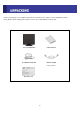
Remove the package cover and place the product on a flat and secure surface or in the installation location. Check whether all the flowing device and accessories are included with the main system. TFT-LCD MONITOR USER MANUAL AC POWER ADAPTOR POWER CORD N.
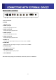
REAR PANEL CONTROL 1. DC 12V Power IN 2. RGB IN RGB signal input 3. VIDEO 1(AV1) IN Composite signal input for AV1 4. VIDEO 1(AV1) OUT Composite looping output for AV1 5. VIDEO 2(AV2) IN Composite signal input for AV2 6. VIDEO 2(AV2) OUT Composite looping output for AV2 7, AUDIO L IN Left side audio signal input. This input is for AV1, AV2, S-VIDEO 8. AUDIO R IN Right side audio signal input. This input is for AV1, AV2, S-VIDEO 9. S-VIDEO (Y/C) IN Y/C separated signal input 10.
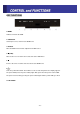
KEY FUNCTIONS 1. MENU Activates and exits the OSD. 2. SOURCE/▼ Select input source, and move the OSD menu. 3. AUTO/▲ Move the OSD menu and auto adjustment of RGB source. 4. ◀ (VOL) Decrease the level of volume and select and set the OSD menu. 5. ▶ Increase the level of volume and select and set the OSD menu. 6. /I Turns the power ON or OFF. There will be a few seconds delay before the display appears. The power LED(next to the power switch) lights with green when the power is turned ON.
OSD MENU DESCRIPTION MENU SELECTION 1. Press the MENU button to access the Main menu. 2. Use the and arrow buttons to highlight a selection. 3. Press the button to select an item. 4. Use the and arrow buttons to highlight a selection. 5. Use the ◀ and arrow buttons to adjust the setting on a selected item. NOTE : If you don’t use RGB mode, RGB SETUP menu is not selected. ■ INPUT Select Inputs can be set to VIDEO1, VIDEO2, S-VIDEO and RGB mode. 1.
1. Press the MENU button and then ▲/▼ button to select the PICTURE menu. 2. Press the ▶ button and then ▲/▼ button to select the adjustment item you need. 3. Press the ▶ button to active the item. ex) If you select the BRIGHTNESS, then the below picture appears on the bottom of screen. 4. Press “ ◀ ▶” to adjust the item. 5. Press the Menu button to move to the previous menu. NOTE : TINT item is for the NTSC input only. ■ SOUND MENU 1. Press the MENU button and then ▲/▼ button to select the SOUND menu. 2.
■ RGB SETUP MENU 1. Press the MENU button and then ▲/▼ button to select the RGB SETUP menu. 2. Press the ▶ button and then ▲/▼ button to select the adjustment item you need. 3. Press the ▶ button to active the item. 4. Press ◀ ▶ to adjust the item 5. Press the MENU button to move to the previous menu.
1. Press the MENU button and then ▲/▼ button to select the FUNCTION menu. 2. Press the ▶ button and then ▲/▼ button to select the adjustment item you need. 3. Press the ▶ button to select the item. 4. Press the MENU button to move to the previous menu. LANGUAGE: Select the language: ENGLISH, FRANCE, GERMAN, ITALIAN, SPANISH. BUTTON LOCK: Select Button lock ON don’t work the Front key. Release the button lock: Push the ▲ and ◀ arrow at the same time for 5 sec then the button is activated.
- 14 SPECIFICATIONS VIDEO Screen Size Viewing Area 17” 19” 338.0 x 270.0mm 376.0 x 301.0mm Active Matrix TFT Pixel Type 1280 x 1024 @ 60Hz (SXGA) Max. Resolution Pixel Pitch 0.264 x 0.264mm 0.294 x 0.294mm 250 cd/㎡ Brightness 800 : 1 Contrast Ratio 5:4 Aspect Ratio 85” /85”/ 75”/ 85” (R/L/T/B) Viewing Angle (H/V) 16.
D-SUB CONNECTOR PIN ASSIGMENTS PIN ASSIGNMENT Pin No. Pin Name Pin No. Pin Name 1 RED VIDEO 9 NC 2 GREEN VIDEO 10 GROUND 3 BLUE VIDEO 11 GROUND 4 NC 12 SDA (for DDC) 5 GROUND 13 H-SYNC 6 RED GROUND 14 V-SYNC 7 GREEN GROUND 15 SCL (for DDC) 8 BLUE GROUND TROUBLESHOOTING GUIDE Troubleshooting Troubleshooting Tip 1. Make sure if the power supply is connected property. No picture 2. Turn on the power. 3. Select the input signal right for the connected port.