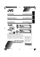
KD-G120R/KD-G120 RECEPTOR CON CD KD-G120R/KD-G120 RECEPTEUR CD KD-G120R/KD-G120 FRANÇAIS ESPAÑOL ENGLISH CD RECEIVER KD-G120R KD-G120 For canceling the display demonstration, see page 6. Para cancelar la demostración en pantalla, consulte la página 6. Pour annuler la démonstration des affichages, référez-vous à la page 6. For installation and connections, refer to the separate manual. Para la instalación y las conexiones, refiérase al manual separado.
ENGLISH Thank you for purchasing a JVC product. Please read all instructions carefully before operation, to ensure your complete understanding and to obtain the best possible performance from the unit. Warning: If you need to operate the unit while driving, be sure to look ahead carefully or you may be involved in a traffic accident. INFORMATION (For U.S.A.) This equipment has been tested and found to comply with the limits for a Class B digital device, pursuant to Part 15 of the FCC Rules.
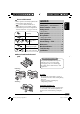
CONTENTS Control panel — KD-G120R and KD-G120 ....... 4 Remote controller — RM-RK50 .............. 5 Getting started ................................. 6 ENGLISH How to read this manual • Button operations are mainly explained with the illustrations in the table below. • is used to indicate an indicator is displayed for the corresponding operation. • Some related tips and notes are explained in “More about this unit” (see pages 11 and 12). Basic operations .................................................
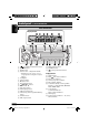
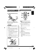
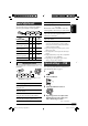
ENGLISH Control panel — KD-G120R and KD-G120 Parts identification Display window 1 (standby/on/attenuator) button 2 SOURCE button 3 BAND button 4 Remote sensor—Only for KD-G120R • DO NOT expose the remote sensor to strong light (direct sunlight or artificial lighting).
Remote controller — RM-RK50 ENGLISH Main elements and features • RM-RK50 is supplied only for KD-G120R. Installing the lithium coin battery (CR2025) 1 Aim the remote controller directly at the remote sensor on the unit. Make sure there is no obstacle in between. 2 Warning: • Do not install any battery other than CR2025 or its equivalent; otherwise, it may explode. • Store the battery in a place where children cannot reach to avoid risk of accident.
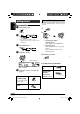
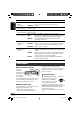
ENGLISH Getting started • See also “General settings — PSM” on pages 9 and 10. Basic operations ~ Turn on the power. ⁄ 1 2 Ÿ ! Basic settings * You cannot select “DISC” as the playback source if there is no disc in the loading slot. 1 Canceling the display demonstrations For FM/AM tuner 2 Setting the clock Select “DEMO,” then “DEMO OFF.” Select “CLOCK H” (hour), then adjust the hour. Select “CLOCK M” (minute), then adjust the minute. Adjust the volume. 3 Finish the procedure. .
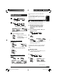
~ ENGLISH Radio operations Reception improves, but stereo effect will be lost. To restore the stereo effect, repeat the same procedure “MONO OFF” appears and the MO indicator goes off. Storing stations in memory Ÿ You can preset six stations for each band. FM station automatic presetting— SSM (Strong-station Sequential Memory) Lights up when receiving an FM stereo broadcast with sufficient signal strength. 1 Select the FM band (FM1 – FM3) you want to store into. Selected band appears.
3 To locate a particular track directly ENGLISH To select a number from 01 – 06: Preset number flashes for a while. To select a number from 07 – 12: Listening to a preset station 1 Prohibiting disc ejection You can lock a disc in the loading slot. 2 Select the preset station (1 – 6) you want. To cancel the prohibition, repeat the same procedure. Disc operations Selecting the playback modes Playing a disc in the unit You can use only one of the following playback modes at a time.
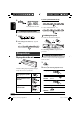
Sound adjustments You can select a preset sound mode suitable to the music genre (C-EQ: custom equalizer). S.BS*2 (super bass), [S.BS ON or S.BS OFF] [01 to 05]*5 Maintain the richness and fullness of the bass sound regardless of how low you set the volume. ENGLISH Indication, [Range] SUB. W (subwoofer), [00 to 08] Adjust the subwoofer output level when a subwoofer is connected. Preset values BAS TRE S.
ENGLISH Indications Selectable settings, [reference page] DEMO Display demonstration DEMO ON : [Initial]; Display demonstration will be activated automatically if no operation is done for about 20 seconds, [6]. DEMO OFF : Cancels. CLOCK H Hour adjustment 1 – 12, [6] [Initial: 1 (1:00)] 00 – 59, [6] CLOCK M Minute adjustment [Initial: 00 (1:00)] L/O MODE Line output mode When connecting an amplifier or a subwoofer, set this correctly.
A dirty disc may not play correctly. If a disc does become dirty, wipe it with a soft cloth in a straight line from center to edge. • Do not use any solvent (for example, conventional record cleaner, spray, thinner, benzine, etc.) to clean discs. Do not use the following discs: Sticker Warped disc To play new discs New discs may have some rough spots around the inner and outer edges. If such a disc is used, this unit may reject the disc.
ENGLISH – Discs are dirty or scratched. – Moisture condensation occurs on the lens inside the unit. – The pickup lens inside the unit is dirty. – CD-R/CD-RW on which the files are written with “Packet Write” method. – There are improper recording conditions (missing data, etc.) or media conditions (stain, scratch, warp, etc.). • CD-RWs may require a longer readout time since the reflectance of CD-RWs is lower than that of regular CDs.
AUDIO AMPLIFIER SECTION Power Output: 17 W RMS × 4 Channels at 4 Ω and ≤ 1% THD+N Signal to Noise Ratio: 80 dBA (reference: 1 W into 4 Ω) CD PLAYER SECTION Type: Compact disc player Signal Detection System: Non-contact optical pickup (semiconductor laser) Number of channels: 2 channels (stereo) Frequency Response: 5 Hz to 20 000 Hz Dynamic Range: 96 dB Signal-to-Noise Ratio: 98 dB Wow and Flutter: Less than measurable limit ENGLISH Specifications GENERAL Load Impedance: 4 Ω (4 Ω to 8 Ω allowance) Tone C
Having TROUBLE with operation? Please reset your unit Refer to page of How to reset your unit Still having trouble?? USA ONLY Call 1-800-252-5722 http://www.jvc.com We can help you! EN, SP, FR © 2005 Victor Company of Japan, Limited Rear_KD-G120R_120[J]ff.
KD-G120R/KD-G120 Installation/Connection Manual Manual de instalación/conexión Manuel d’installation/raccordement GET0330-002A 1005DTSMDTJEIN EN, SP, FR © 2005 Victor Company of Japan, Limited [J] ENGLISH FRANÇAIS ESPAÑOL This unit is designed to operate on 12 V DC, NEGATIVE ground electrical systems. If your vehicle does not have this system, a voltage inverter is required, which can be purchased at JVC car audio dealers.
INSTALLATION (IN-DASH MOUNTING) INSTALACION (MONTAJE EN EL TABLERO DE INSTRUMENTOS) INSTALLATION (MONTAGE DANS LE TABLEAU DE BORD) The following illustration shows a typical installation. If you have any questions or require information regarding installation kits, consult your JVC car audio dealer or a company supplying kits. • If you are not sure how to install this unit correctly, have it installed by a qualified technician. La siguiente ilustración muestra una instalación típica.
ENGLISH ESPAÑOL ELECTRICAL CONNECTIONS A FRANÇAIS CONEXIONES ELECTRICAS RACCORDEMENTS ELECTRIQUES Typical connections / Conexiones tipicas / Raccordements typiques Before connecting: Check the wiring in the vehicle carefully. Antes de la conexión: Verifique atentamente el conexionado del Avant de commencer la connexion: Vérifiez attentivement Incorrect connection may cause serious damage to this unit.
B Connecting the external amplifier or subwoofer / Conexión del amplificador o subwoofer exterior / Connexion d’un amplificateur extérieur ou d’un caisson de grave You can connect an amplifier to upgrade your car stereo system. • Connect the remote lead (blue with white stripe) to the remote lead of the other equipment so that it can be controlled through this unit. • Disconnect the speakers from this unit, connect them to the amplifier. Leave the speaker leads of this unit unused.
CD RECEIVER KD-G124/KD-G123 KD-G124 KD-G123 For canceling the display demonstration, see page 5. For installation and connections, refer to the separate manual. INSTRUCTIONS GET0332-001A [UI] Cover_KD-G124_123[UI]f.
Thank you for purchasing a JVC product. Please read all instructions carefully before operation, to ensure your complete understanding and to obtain the best possible performance from the unit. IMPORTANT FOR LASER PRODUCTS 1. CLASS 1 LASER PRODUCT 2. CAUTION: Do not open the top cover. There are no user serviceable parts inside the unit; leave all servicing to qualified service personnel. 3. CAUTION: Visible and invisible laser radiation when open and interlock failed or defeated.
How to read this manual • Button operations are mainly explained with the illustrations in the table below. • is used to indicate an indicator is displayed for the corresponding operation. • Some related tips and notes are explained in “More about this unit” (see pages 11 and 12). Press briefly. CONTENTS Control panel — KD-G124 and KD-G123 ........ 4 Getting started ................................. 5 Basic operations .................................................... 5 Radio operations ................
Control panel — KD-G124 and KD-G123 Parts identification Display window 1 2 3 4 5 6 7 8 9 p q w e r t y u i (standby/on/attenuator) button SOURCE button BAND button Loading slot Display window 0 (eject) button EQ (equalizer) button ¢/4 buttons Control dial SEL (select) button DISP (display) button MO (monaural) button SSM (Strong-station Sequential Memory) button Number buttons RPT (repeat) button RND (random) button M MODE button (control panel release) button Display window o ; a s d f DISC indicator
Getting started • See also “General settings — PSM” on page 9. Basic operations ~ Basic settings Turn on the power. 1 2 Ÿ 1 Canceling the display demonstrations * You cannot select “DISC” as the playback source if there is no disc in the loading slot. ! For FM/AM tuner ⁄ Adjust the volume. Select “DEMO,” then “DEMO OFF.” 2 Setting the clock Select “CLOCK H” (hour), then adjust the hour. Select “CLOCK M” (minute), then adjust the minute. 3 Finish the procedure. . level appears.
Radio operations When an FM stereo broadcast is hard to receive ~ Ÿ Lights up when monaural mode is activated. Lights up when receiving an FM stereo broadcast with sufficient signal strength. Reception improves, but stereo effect will be lost. To restore the stereo effect, repeat the same procedure “MONO OFF” appears and the MO indicator goes off. Selected band appears. ! Start searching for a station. Storing stations in memory You can preset six stations for each band.
Manual presetting Ex.: Storing FM station of 92.5 MHz into preset number 4 of the FM1 band. 1 Disc operations Playing a disc in the unit 2 All tracks will be played repeatedly until you change the source or eject the disc. To stop play and eject the disc 3 To fast-forward or reverse the track Preset number flashes for a while.
Selecting the playback modes You can use only one of the following playback modes at a time. Adjusting the sound You can adjust the sound characteristics to your preference. 1 2 Select your desired playback mode. 7 Repeat play Mode *1 Displayed only when “L/O MODE” is set to “WOOFER” (see page 9). Plays repeatedly TRK RPT RPT OFF Indication, [Range] : The current track. : Cancels. BAS*2 (bass), [–06 to +06] Adjust the bass. 7 Random play TRE*2 (treble), [–06 to +06] Adjust the treble.
General settings — PSM You can change PSM (Preferred Setting Mode) items listed in the table that follows. 3 Adjust the PSM item selected. 4 Repeat steps 2 and 3 to adjust other PSM items if necessary. 5 Finish the procedure. 1 2 Select a PSM item. Indications Selectable settings, [reference page] DEMO Display demonstration DEMO ON : [Initial]; Display demonstration will be activated automatically if no operation is done for about 20 seconds, [5]. DEMO OFF : Cancels.
Maintenance How to clean the connectors Frequent detachment will deteriorate the connectors. To minimize this possibility, periodically wipe the connectors with a cotton swab or cloth moistened with alcohol, being careful not to damage the connectors. To play new discs New discs may have some rough spots around the inner and outer edges. If such a disc is used, this unit may reject the disc. To remove these rough spots, rub the edges with a pencil or ball-point pen, etc.
More about this unit Basic operations Inserting a disc Turning on the power • When a disc is inserted upside down, the disc automatically ejects. • Do not insert 8 cm discs (single CD) and unusual shape discs (heart, flower, etc.) into the loading slot. • By pressing SOURCE on the unit, you can also turn on the power. If the source is ready, playback also starts.
Ejecting a disc General settings—PSM • If the ejected disc is not removed within 15 seconds, the disc is automatically inserted again into the loading slot to protect it from dust. (Disc will not play this time.) • If you change the “AMP GAIN” setting from “HIGH PWR” to “LOW PWR” while the volume level is set higher than “VOL 30,” the unit automatically changes the volume level to “VOL 30.” Troubleshooting What appears to be trouble is not always serious.
Specifications AUDIO AMPLIFIER SECTION Maximum Power Output: Front: 50 W per channel Rear: 50 W per channel Continuous Power Output (RMS): Front: 19 W per channel into 4 Ω, 40 Hz to 20 000 Hz at no more than 0.8% total harmonic distortion. Rear: 19 W per channel into 4 Ω, 40 Hz to 20 000 Hz at no more than 0.8% total harmonic distortion.
Having TROUBLE with operation? Please reset your unit Refer to page of How to reset your unit EN © 2005 Victor Company of Japan, Limited Rear_KD-G124_123[UI]f.
KD-G124/KD-G123 Installation/Connection Manual GET0332-002A 1005DTSMDTJEIN EN © 2005 Victor Company of Japan, Limited [UI] This unit is designed to operate on 12 V DC, NEGATIVE ground electrical systems. If your vehicle does not have this system, a voltage inverter is required, which can be purchased at JVC car audio dealers. WARNINGS To prevent short circuits, we recommend that you disconnect the battery’s negative terminal and make all electrical connections before installing the unit.
ELECTRICAL CONNECTIONS A Typical connections Before connecting: Check the wiring in the vehicle carefully. Incorrect connection may cause serious damage to this unit. The leads of the power cord and those of the connector from the car body may be different in color. 1 2 3 Connect the colored leads of the power cord in the order specified in the illustration below. Connect the antenna cord. Finally connect the wiring harness to the unit.
KD-G126/KD-G125 ENGLISH CD RECEIVER KD-G126/KD-G125 KD-G126 KD-G126 KD-G125 KD-G125 For canceling the display demonstration, see page 5. 5 For installation and connections, refer to the separate manual. INSTRUCTIONS GET0331-001A [U/UH] Cover_KD-G126_001A_f.
ENGLISH Thank you for purchasing a JVC product. Please read all instructions carefully before operation, to ensure your complete understanding and to obtain the best possible performance from the unit. IMPORTANT FOR LASER PRODUCTS 1. CLASS 1 LASER PRODUCT 2. CAUTION: Do not open the top cover. There are no user serviceable parts inside the unit; leave all servicing to qualified service personnel. 3. CAUTION: Visible and invisible laser radiation when open and interlock failed or defeated.
Press briefly. CONTENTS Control panel — KD-G126 and KD-G125 ........ 4 Getting started ................................. 5 Basic operations .................................................... 5 ENGLISH How to read this manual • Button operations are mainly explained with the illustrations in the table below. • is used to indicate an indicator is displayed for the corresponding operation. • Some related tips and notes are explained in “More about this unit” (see pages 11 and 12). Radio operations ......
ENGLISH Control panel — KD-G126 and KD-G125 Parts identification Display window 1 2 3 4 5 6 7 8 9 p q w e r t y u i (standby/on/attenuator) button SOURCE button BAND button Loading slot Display window 0 (eject) button EQ (equalizer) button ¢/4 buttons Control dial SEL (select) button DISP (display) button MO (monaural) button SSM (Strong-station Sequential Memory) button Number buttons RPT (repeat) button RND (random) button M MODE button (control panel release) button Display window o ; a s d f DISC i
Getting started Turn on the power. 1 ENGLISH • See also “General settings — PSM” on page 9. Basic operations ~ Basic settings 2 Ÿ 1 Canceling the display demonstrations * You cannot select “DISC” as the playback source if there is no disc in the loading slot. ! For FM/AM tuner ⁄ Adjust the volume. Select “DEMO,” then “DEMO OFF.” 2 Setting the clock Select “CLOCK H” (hour), then adjust the hour. Select “CLOCK M” (minute), then adjust the minute. 3 Finish the procedure. . level appears.
ENGLISH Radio operations When an FM stereo broadcast is hard to receive ~ Ÿ Lights up when monaural mode is activated. Lights up when receiving an FM stereo broadcast with sufficient signal strength. Reception improves, but stereo effect will be lost. To restore the stereo effect, repeat the same procedure “MONO OFF” appears and the MO indicator goes off. Selected band appears. ! Start searching for a station. Storing stations in memory You can preset six stations for each band.
Ex.: Storing FM station of 92.5 MHz into preset number 4 of the FM1 band. 1 Disc operations ENGLISH Manual presetting Playing a disc in the unit 2 All tracks will be played repeatedly until you change the source or eject the disc. To stop play and eject the disc 3 To fast-forward or reverse the track Preset number flashes for a while.
ENGLISH Selecting the playback modes You can use only one of the following playback modes at a time. Adjusting the sound You can adjust the sound characteristics to your preference. 1 2 Select your desired playback mode. 7 Repeat play Mode *1 Displayed only when “L/O MODE” is set to “WOOFER” (see page 9). Plays repeatedly TRK RPT RPT OFF Indication, [Range] : The current track. : Cancels. BAS*2 (bass), [–06 to +06] Adjust the bass. 7 Random play TRE*2 (treble), [–06 to +06] Adjust the treble.
You can change PSM (Preferred Setting Mode) items listed in the table that follows. ENGLISH General settings — PSM 3 Adjust the PSM item selected. 4 Repeat steps 2 and 3 to adjust other PSM items if necessary. 5 Finish the procedure. 1 2 Select a PSM item. Indications Selectable settings, [reference page] DEMO Display demonstration DEMO ON : [Initial]; Display demonstration will be activated automatically if no operation is done for about 20 seconds, [5]. DEMO OFF : Cancels.
ENGLISH Maintenance How to clean the connectors Frequent detachment will deteriorate the connectors.To minimize this possibility, periodically wipe the connectors with a cotton swab or cloth moistened with alcohol, being careful not to damage the connectors. To play new discs New discs may have some rough spots around the inner and outer edges. If such a disc is used, this unit may reject the disc. To remove these rough spots, rub the edges with a pencil or ball-point pen, etc.
Basic operations Inserting a disc Turning on the power • When a disc is inserted upside down, the disc automatically ejects. • Do not insert 8 cm discs (single CD) and unusual shape discs (heart, flower, etc.) into the loading slot. • By pressing SOURCE on the unit, you can also turn on the power. If the source is ready, playback also starts.
ENGLISH Ejecting a disc General settings—PSM • If the ejected disc is not removed within 15 seconds, the disc is automatically inserted again into the loading slot to protect it from dust. (Disc will not play this time.) • If you change the “AMP GAIN” setting from “HIGH PWR” to “LOW PWR” while the volume level is set higher than “VOL 30,” the unit automatically changes the volume level to “VOL 30.” Troubleshooting What appears to be trouble is not always serious.
AUDIO AMPLIFIER SECTION Maximum Power Output: Front: 50 W per channel Rear: 50 W per channel Continuous Power Output (RMS): Front: 19 W per channel into 4 Ω, 40 Hz to 20 000 Hz at no more than 0.8% total harmonic distortion. Rear: 19 W per channel into 4 Ω, 40 Hz to 20 000 Hz at no more than 0.8% total harmonic distortion.
Having TROUBLE with operation? Please reset your unit Refer to page of How to reset your unit EN, TH © 2005 Victor Company of Japan, Limited Rear_KD-G126_001A_f.
KD-G126/KD-G125 Installation/Connection Manual °“√µ‘¥µ—Èß/§ŸË¡◊Õ°“√µ‘¥µ—Èß GET0331-006A 1005DTSMDTJEIN EN, TH © 2005 Victor Company of Japan, Limited [U/UH] ENGLISH ‰∑¬ This unit is designed to operate on 12 V DC, NEGATIVE ground electrical systems. If your vehicle does not have this system, a voltage inverter is required, which can be purchased at JVC car audio dealers.
INSTALLATION (IN-DASH MOUNTING) °“√µ‘¥µ—Èß (°“√ª√–°Õ∫·ºßÀπÈ“ª—∑¡Ï‡¢È“) The following illustration shows a typical installation. If you have any questions or require information regarding installation kits, consult your JVC car audio dealer or a company supplying kits. • If you are not sure how to install this unit correctly, have it installed by a qualified technician.
ENGLISH ‰∑¬ ELECTRICAL CONNECTIONS A °“√‡™◊ËÕ¡‚¥¬„™È ‰øøÈ“ Typical connections / °“√‡™◊ËÕ¡µËÕ·∫∫ª°µ Before connecting: Check the wiring in the vehicle carefully. Incorrect connection may cause serious °ËÕ•∑”°“•‡™•ËÕ¡µËÕ: µ•«®†Õ•°“•‡¥‘•†“¬‰ø„•••¬•µÏլ˓ߕ–¡—¥•–«—լ˓„ÀȺ‘¥æ•“¥„•°“•‡™•ËÕ¡µËÕ™ÿ¥ª•–°Õ•™ÿ¥•’ damage to this unit. The leads of the power cord and those of the connector from the car body may be different in color.
B Connecting the external amplifier or subwoofer / µËÕ·Õ¡ª≈‘ø“¬‡ÕÕ√ÏÀ√◊Õ´—∫«Ÿø‡øÕ√ϥȓππÕ° You can connect an amplifier to upgrade your car stereo system. • Connect the remote lead (blue with white stripe) to the remote lead of the other equipment so that it can be controlled through this unit. • Disconnect the speakers from this unit, connect them to the amplifier. Leave the speaker leads of this unit unused.
FRANÇAIS ENGLISH CD RECEIVER RECEPTEUR CD KD-G162/KD-G161 KD-G162 KD-G162 KD-G161 KD-G161 For canceling the display demonstration, see page 5. Pour annuler la démonstration des affichages, référez-vous à la page 5. For installation and connections, refer to the separate manual. Pour l’installation et les raccordements, se référer au manuel séparé. INSTRUCTIONS MANUEL D’INSTRUCTIONS GET0334-003A [EX/EU] Cover_KD-G162_161[EX_EU]f.
ENGLISH Thank you for purchasing a JVC product. Please read all instructions carefully before operation, to ensure your complete understanding and to obtain the best possible performance from the unit. IMPORTANT FOR LASER PRODUCTS 1. CLASS 1 LASER PRODUCT 2. CAUTION: Do not open the top cover. There are no user serviceable parts inside the unit; leave all servicing to qualified service personnel. 3. CAUTION: Visible and invisible laser radiation when open and interlock failed or defeated.
Press briefly. CONTENTS Control panel — KD-G162 and KD-G161 ........ 4 Getting started ................................. 5 Basic operations .................................................... 5 ENGLISH How to read this manual • Button operations are mainly explained with the illustrations in the table below. • is used to indicate an indicator is displayed for the correspnding operation. • Some related tips and notes are explained in “More about this unit” (see pages 14 and 15). Radio operations .......
ENGLISH Control panel — KD-G612/KD-G611/KD-G511 KD-G162 and KD-G161 Parts identification Display window 1 2 3 4 5 6 7 8 9 p q w e r t y u (standby/on/attenuator) button SOURCE button BAND button Loading slot Display window 0 (eject) button TP/PTY (traffic programme/programme type) button ¢/4 buttons Control dial SEL (select) button DISP (display) button EQ (equalizer) button MO (monaural) button SSM (Strong-station Sequential Memory) button Number buttons RPT (repeat) button RND (random) button i M MODE
Getting started Basic operations • See also “General settings — PSM” on pages 11 and 12. ~ 1 Turn on the power. ENGLISH Basic settings 2 Ÿ * You cannot select “DISC” as the playback source if there is no disc in the unit. ! For FM/AM tuner ⁄ Adjust the volume. 1 Canceling the display demonstrations Select “DEMO,” then “DEMO OFF.” 2 Setting the clock Select “CLOCK H” (hour), then adjust the hour. Select “CLOCK M” (minute), then adjust the minute.
ENGLISH Radio operations When an FM stereo broadcast is hard to receive ~ Ÿ Lights up when monaural mode is activated. Lights up when receiving an FM stereo broadcast with sufficient signal strength. Reception improves, but stereo effect will be lost. To restore the stereo effect, repeat the same procedure. “MONO OFF” appears and the MO indicator goes off. Selected band appears. ! Storing stations in memory Start searching for a station. When a station is received, searching stops.
Ex.: Storing FM station of 92.5 MHz into preset number 4 of the FM1 band. 1 FM RDS operations What you can do with RDS RDS (Radio Data System) allows FM stations to send an additional signal along with their regular programme signals.
ENGLISH ! Start searching for your favorite programme. If there is a station broadcasting a programme of the same PTY code as you have selected, that station is tuned in. Storing your favorite programme types You can store six favorite programme types. Preset programme types in the number buttons (1 to 6): 1 2 Select a PTY code (see page 7). Select the preset number (1 – 6) you want to store into.
When driving in an area where FM reception is not sufficient enough, this unit automatically tunes in to another FM RDS station of the same network, possibly broadcasting the same programme with stronger signals (see the illustration on page 15). When shipped from the factory, NetworkTracking Reception is activated. To change the Network-Tracking Reception setting, see “AF-REG” on page 11.
ENGLISH Sound adjustments Adjusting the sound You can select a preset sound mode suitable to the music genre (C-EQ: custom equalizer). You can adjust the sound characteristics to your preference. 1 1 2 2 Indication, [Range] Ex.: When “ROCK” is selected BAS*1 (bass), [–06 to +06] Adjust the bass.
You can change PSM (Preferred Setting Mode) items listed in the table below. ENGLISH General settings — PSM 3 Adjust the PSM item selected. 4 Repeat steps 2 and 3 to adjust other PSM items if necessary. 5 Finish the procedure. 1 2 Select a PSM item. Indications Selectable settings, [reference page] DEMO Display demonstration DEMO ON : [Initial]; Display demonstration will be activated automatically if no operation is done for about 20 seconds, [5]. DEMO OFF : Cancels.
ENGLISH Indications Selectable settings, [reference page] PTY-STBY PTY standby Activates PTY Standby Reception with one of the PTY codes, [8]. OFF [Initial] = PTY codes, [15] = (back to the beginning) TA VOL Traffic announcement volume [Initial: VOL 15]; VOL 00 — VOL 30 or 50*, [8] P-SEARCH Programme search ON OFF : Using the AF data, the unit tunes in to another frequency broadcasting the same programme as the original preset RDS station is if the preset station signals are not sufficient.
How to clean the connectors Frequent detachment will deteriorate the connectors. To minimize this possibility, periodically wipe the connectors with a cotton swab or cloth moistened with alcohol, being careful not to damage the connectors. Connector Moisture condensation Moisture may condense on the lens inside the CD player in the following cases: • After starting the heater in the car. • If it becomes very humid inside the car. Should this occur, the CD player may malfunction.
ENGLISH More about this unit Basic operations Turning on the power • By pressing SOURCE on the unit, you can also turn on the power. If the source is ready, playback also starts. Turning off the power • If you turn off the power while listening to a disc, disc play will start from where playback has been stopped previously, next time you turn on the power. Selecting the sources • When no disc is loaded in the unit, “DISC” cannot be selected.
General settings—PSM • Use only “finalized” CD-Rs or CD-RWs. • This unit can play back multi-session discs; however, unclosed sessions will be skipped while playing. • Some CD-Rs or CD-RWs may not play back on this unit because of their disc characteristics, or for the following causes: – Discs are dirty or scratched. – Moisture condensation occurs on the lens inside the unit. – The pickup lens inside the unit is dirty. – CD-R/CD-RW on which the files are written with “Packet Write” method.
ENGLISH Troubleshooting What appears to be trouble is not always serious. Check the following points before calling a service center. FM/AM General Symptoms Remedies/Causes • Sound cannot be heard from the speakers. • Adjust the volume to the optimum level. • Check the cords and connections. • The unit does not work at all. Reset the unit (see page 2). • SSM automatic presetting does not work. Store stations manually. • Static noise while listening to the radio. Connect the aerial firmly.
AUDIO AMPLIFIER SECTION Maximum Power Output: Front: 45 W per channel Rear: 45 W per channel Continuous Power Output (RMS): Front: 17 W per channel into 4 Ω, 40 Hz to 20 000 Hz at no more than 0.8% total harmonic distortion. Rear: 17 W per channel into 4 Ω, 40 Hz to 20 000 Hz at no more than 0.8% total harmonic distortion.
Having TROUBLE with operation? Please reset your unit Refer to page of How to reset your unit Vous avez des PROBLÈMES de fonctionnement? Réinitialisez votre appareil Référez-vous à la page intitulée Comment réinitialiser votre appareil EN, FR © 2005 Victor Company of Japan, Limited Rear_KD-G162_161[EX_EU]f.
KD-G162/KD-G161 Installation/Connection Manual Manuel d’installation/raccordement GET0334-010A 1005DTSMDTJEIN EN, FR © 2005 Victor Company of Japan, Limited [EX/EU] ENGLISH FRANÇAIS This unit is designed to operate on 12 V DC, NEGATIVE ground electrical systems. If your vehicle does not have this system, a voltage inverter is required, which can be purchased at JVC IN-CAR ENTERTAINMENT dealers. Cet appareil est conçu pour fonctionner sur des sources de courant continu de 12 V à masse NEGATIVE.
INSTALLATION (IN-DASH MOUNTING) INSTALLATION (MONTAGE DANS LE TABLEAU DE BORD) The following illustration shows a typical installation. If you have any questions or require information regarding installation kits, consult your JVC IN-CAR ENTERTAINMENT dealer or a company supplying kits. • If you are not sure how to install this unit correctly, have it installed by a qualified technician. L’illustration suivante est un exemple d’installation typique.
ENGLISH A FRANÇAIS If your car is equipped with the ISO connector / Si votre voiture est équippée d’un connecteur ISO • Connect the ISO connectors as illustrated. • Connectez les connecteurs ISO comme montré sur l’illustration. For some VW/Audi or Opel (Vauxhall) automobile / Pour certaine voiture VW/Audi ou Opel (Vauxhall) You may need to modify the wiring of the supplied power cord as illustrated. • Contact your authorized car dealer before installing this unit.
C Connecting the external amplifier / Connexion d’un amplificateur extérieur Vous pouvez connecter un amplificateur pour améliorer votre système autoradio. • Connectez le fil de commande à distance (bleu avec bande blanche) au fil de commande à distance de l’autre appareil de façon qu’il puisse être commandé via cet appareil. • Déconnectez les enceintes de cet appareil et connectez-les à l’amplificateur. Laissez les fils d’enceintes de cet appareil inutilisés.