KS-FX922R SERVICE MANUAL CASSETTE RECEIVER KS-FX922R Area Suffix E ... Continental Europe KS-FX922R DISP DAB TP RDS PTY 7 8 9 10 11 12 MO Contents Safety precaution ------------------------------------- 1-2 Location of main parts ------------------------------- 1-3 Disassembly method -------------------------------- 1-4 Adjustment method ---------------------------------- 1-11 Description of major ICs ---------------------------- 1-15 COPYRIGHT 2001 VICTOR COMPANY OF JAPAN, LTD. No.49596 Feb.
KS-FX922R Adjustment method Test Instruments reqired for adjustment Tuner section BAND STEP 1.Digital osclloscope(100MHz) 2.Frequency Counter meter 3.Electric voltmeter 4.Wow & flutter meter 5.Test Tapes FM : 100kHz (Seek), 50kHz (Manual) AM : 9kHz step Preset Memory Initialization for DOLBY level measurement VT724 VT739 VT712 VT703 For playback frequency measurement For wow flutter & tape speed measurement For head azimuth measurement 6.
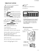
KS-FX922R Arrangment of adjusting Head amplifier board section (Reverse side) VR402:Rch (Dolby NR level adj) Q401 C409 R411 1 R424 C408 R417 B412 R414 R405 R404 1 C403 B406 R407 CP403 1 17 R401 R406 B407 R415 C416 R418 R419 R409 21 IC401 B414 C407 B411 C415 FSMW1101A R416 B408 1 C414 B403 D402 CP402 2 11 R425 B410 Q403 C419 B404 Q402 R420 CP401 B409 R408 31 1 IC402 B401 TPP C404 C405 R421 R422 1 VR401 B416 R410 C413 R402 C410 R412 C411 R413 C418
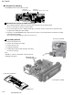
KS-FX922R Extension cord The mechanism should be directly connected to the board using the extension wire.
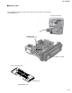
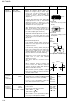
KS-FX922R Item 1. Head azimuth adjustment Conditions Test tape: SCC-1659 VT703(10kHz) Adjustment and Confirmation methods S.Values Adjust Head height adjustment Adjust the azimuth directly. When you adjust the height using a mirror tape, remove the cassette housing from the mechanism chassis. After installing the cassette housing, perform the azimuth adjustment. A line 1. Load the SCC-1659 mirror tape.
KS-FX922R Block Diagram SUB MOTOR SWITCH TAPE END.STANDBY 5 MAIN MOTOR HEAD CN402 CN403 TO SPEAKER CONNECTOR TO REAR LINE OUT CP901 J321 IC801 CHANGER CONTROL HD74HC126FP-X 3 CD RCH CD LCH JBUS SI JBUS SO JBUS I/O JBUS SCK J1 AM FM 2 IC161 E.
Standard schematic diagrams KS-FX922R Receiver & System control circuit section 5 4 3 2 FM Radio Signal/Radio Main Signal 1 AM Radio Signal Tape PB/Main Signal A B C D E F G 2-3
KS-FX922R KS-FX922R Mecha control circuit section 5 4 3 2 Tape PB/Main Signal 1 A B C D 2-4 E F G
KS-FX922R LCD driver & Operation switch circuit section 5 4 3 2 1 A B C D E F G 2-5
KS-FX922R SERVICE MANUAL CASSETTE RECEIVER KS-FX922R DISP DAB TP RDS PTY 7 8 9 10 11 12 MO Area Suffix EX Centeal Europe This model is KS-FX922RE EX that is added to the preceding model, theKS-FX922R E . Therefore the service manual for this model is consisting of Parts list only. For others, please refer to the service manual of KS-FX922R E (issue No.49596). COPYRIGHT 2001 VICTOR COMPANY OF JAPAN, LTD. No.49631 Mar.
KS-FX922R Parts list(Accessories) A Iten A 2 Parts name INST.BOOK (LANGUAGE) Block No.M4MM P3-17 Parts number E GET0017-002A (SPA,ITA,SWE,FIN) EX Q'ty 1 ---------------------------- VICTOR COMPANY OF JAPAN, LIMITED MOBILE ELECTRONICS DIVISION PERSONAL & MOBILE NETWORK BUSINESS UNIT. 10-1,1Chome,Ohwatari-machi,Maebashi-city,371-8543,Japan (No.