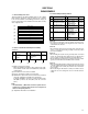
KV-V8 SERVICE MANUAL MOBILE VIDEO CASSETTE PLAYER KV-V8 Comparison table Item Signal system Area Continental KV-V8E KV-V8J PAL NTSC Europe U.S.A. Area Suffix E J Continental Europe North America Contents q Specifications q CAUTION q Instructions 1. DISASSEMBLY 1.1 Disassembly flow chart . . . . . . . . . . . . . . . . . . . . . . . . . . . . . . . . . . . . . . 1.2 How to read the disassembly and assembly . . . . . . . . . . . . . . . . . 1.3 Disassembly/assembly method . . . . . . . . . . . . .
Specificatios (KV-V8J) General •Power supply •Dimensions •Mass •Allowable working temperature •Allowable relative humidity •Allowable conservation temperature : DC12 V (11V-16V allowable)Negative ground : 259 mm x 94 mm x 270 mm (10-1/4"x 3-3/4"x 10-11/16") (width x height x depth) : 3.2 kg (7.
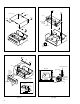
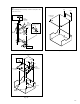
SECTION 1 DISASSEMBLY 1.1 Disassembly flow chart 1.3 Disassembly/assembly method This flowchart lists the disassembling steps for the cabinet parts and P.C. boards in order to gain access to item(s) to be serviced. When reassembling, perform the step(s) in reverse order. Bend, route and dress the flat cables as they were originally laid. Step/ Part Name Loc No.
(S3a) (S3a) (S1c) [1] Top cover (S1b) (L3a) (S1c) (S1a) [3] Cassette housing assembly Switch lever A (L3a) (S1a) A REC safety switch Fig. D3a Fig. D1 (S2a) Stay (S2a) [2] SW board assembly WR2a Loading motor belt G Rear side Pinch plate WR2b Foil side (L2a) CN3006 [2] Front panel assembly Hole align with hole in deck Door opener “a” (L2a) Detail “G” Control cam SW board WR2a (L2b) WR2b Chassis Main board CN3006 Fig. D2 1-2 Front board Fig.
Note: When installing the Drum assembly, secure the screws (S4a – S4c) in the order of a , b , c . Not used Inertia plate (S6b) (S6a) [6] Main board assembly (L5b) (S4a) WR4a Supporting tape side WR4b Supporting tape side (S4c) CN1 Not used Cleaner assembly (S4b) [4] Drum assembly (L5a) CN1 Not used Fig. D6 Fig. D4 (S5a) Not used WR4 WR5a (S5b) WR5c CN1 [5] Mechanism assembly WR5b Red line: CN3003 pin1 CN3005 CN3003 (L5a) Spacer Fig.
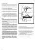
1.4 Service position This unit has been designed so that the Mechanism and Main board assemblies can be removed together from the chassis assembly. Before diagnosing or servicing the circuit boards, take out the major parts from the chassis assembly. Main board assembly TP4001 TP2253 CTL.P A FM TP111 D.FF TP106 PB FM 1.4.1 How to set the "Service position” (1) Refer to the disassembly procedure and perform disassembly of the major parts before removing the Cassette housing assembly.
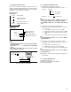
1.6.1 1.6 Emergency display function This unit has a function for storing the history of the past two emergencies (EMG) and displaying them on each FDP (or OSD). With the status of the VCR and mechanism at the moment an emergency occurred can also be confirmed. Displaying the EMG information (1) Transmit the code “59” from the Jig RCU. The FDP shows the EMG content in the form of “E: * * : * * ”.
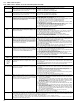
1.6.3 EMG content description Note: EMG contents “E08/E09” are for the model with Dynamic Drum (DD). FDP CONTENT E01: Loading EMG When the mechanism mode cannot be changed to another mode even when the loading motor has rotated for more than 4 seconds in the loading direction, [E:01] is identified and the power is turned off. 1. The mechanism is locked in the middle of mode transition. 2. The mechanism is locked at the loading end due to the encoder position reading error during mode transition. 3.
1.6.4 EMG detail information <1> The status (electrical operation mode) of the VCR and the status (mechanism operation mode/sensor information) of the mechanism in the latest EMG can be confirmed based on the figure in EMG detail information <1> .
3– : Mechanism sensor information [Common table of MN*, HD* and M3*] Mechanism sensor information Display MN* / HD* S-VHS SW 0123456789ABCDEF- VHS VHS VHS VHS VHS VHS VHS VHS S-VHS S-VHS S-VHS S-VHS S-VHS S-VHS S-VHS S-VHS M3* CASS SW REC safety SW Start sensor End sensor Cassette insertion Cassette insertion Cassette insertion Cassette insertion Cassette insertion Cassette insertion Cassette insertion Cassette insertion Cassette ejection Cassette ejection Cassette ejection Cassette ejection Cassette
SECTION 2 MECHANISM ADJUSTMENT 2.1 Before starting repair and adjustment Loading motor 2.1.1 Precautions (1) Unplug the power cord plug of the VCR before using your soldering iron. (2) Take care not to cause any damage to the conductor wires when plugging and unplugging the connectors. (3) Do not randomly handle the parts without identifying where the trouble is. (4) Exercise enough care not to damage the lugs, etc. during the repair work.
2.1.5 Maintenance and inspection 1. Location of major mechanical parts Drum Assembly Stator Assembly A/C Head Capstan Motor Loading Motor Guide Rail Belt (Loading Motor) Pinch Roller Arm Assembly FE Head Guide Arm Assembly Tension Arm Assembly Pole Base Assembly (SUP) Lever Assembly Control Plate Control Cam Change Lever Assembly Tension Band Assembly Slide Plate Reel Disk Assembly Reel Disk Assembly (TU) (SUP) Pole Base Assembly (TU) Fig.
(1) When cleaning the upper drum (especially the video head), soak a piece of closely woven cloth or Kimu-wipe with alcohol and while holding the cloth onto the upper drum by the fingers, turn the upper drum counterclockwise. Note: • Absolutely avoid sweeping the upper drum vertically as this will cause damage to the video head. (2) To clean the parts of the tape transport system other than the upper drum, use a piece of closely woven cloth or a cotton swab soaked with alcohol.
2.2 Replacement of major parts (B) 2.2.1 Before starting disassembling This mechanism has an exclusive operation mode provided for disassembling and installation of the mechanism (Mechanism assembling mode), and it is suggested to set the mechanism to this mode before disassembly and installation.The “Mechanism assembling mode” is not generally used and becomes available by manual setting only.
2.2.6 Loading motor (1) Remove the belt from the worm gear assembly. (2) Take out the 2 screws (A) and then remove the loading motor. (B) (B) Sub deck assembly Note: • When installing the loading motor, hold it so that the label faces upward. Also take care with the wire colors. Red line (to pin 1 of connector for the loading motor) Label (Top view) Loading motor (A) Capstan motor (A) Worm gear assembly Fig.2-2-7c Belt Fig.2-2-6a 2.2.
Reel disk assembly (take up) Control cam Claw (a) Sub brake assembly (take up) Fig.2-2-9b (a) 2.2.10 Control plate (1) Take out the slit washer, disengage the 2 hooks while lifting the control cam side of the control plate, and remove the control plate. Notes: • After removing the control plate, be careful not to turn the main deck assembly upside down. Otherwise, parts such as the idler lever and clutch unit (take up) may slip out.
2.2.13 Change lever assembly, rotary encoder (1) Slide the change lever assembly in the direction of the arrow and remove. (2) While pushing the claws on both sides in the disengaging directions, take out the rotary encoder. (3) When attaching the rotary encoder, position it so that the alignment markings face each other as shown in Fig. 22-13a, then attach the rotary encoder. Tension arm assembly Tension arm lever Notes: • Before removing the change lever assembly, it is required to remove the belt (Fig.
2.2.16 Guide rail (1) Take out the 5 screws (A) and 1 screw (B). (2) By expanding the rails on the outer sides of the guide rail, remove the 2 pole base assemblies (supply, take up). (3) Disengage the 4 claws and remove the guide rail. 2.2.18 Rotor assembly Note: • Before removing the guide rail, it is required to remove the drum assembly. 2. How to install (1) Match the phases of the upper drum assembly and the rotor assembly as indicated in Fig.2-2-18a.
Spring Collar assembly Brush Loosen 1.5 mm hexagonal wrench Cap Upper drum assembly Washer Collar assembly Upper drum assembly Shaft Lower drum assembly Fig. 2-2-19c Press Fig. 2-2-19a 2. How to install (1) Clean the coil parts of the lower drum assembly and the newly installed upper drum assembly with an air brush in advance. (See Fig.2-2-19b.) (2) Install a new washer and upper drum assembly on the drum shaft. (See Fig.2-2-19a.) (3) Install the cap to the upper drum assembly.
2.3.2 Loading arm assemblies (supply, take up) (1) Attach the loading arm assembly (supply) and loading arm assembly (take up) so that the alignment markings on their gears face each other and the holes on their arms are respectively aligned with the holes on the main deck. (2) Attach the guide rail, attach the pole base assemblies onto the extremities of the arms, then perform the unloading operation so that the pole base assemblies come to the most forward positions.
2.3.5 Control plate (1) Attach the control plate by aligning the 2 alignment holes on the control plate with the alignment holes on the main deck assembly as well as the alignment holes on the take up lever. As the take up lever is pulled by a tension spring, use a pair of tweezers or similar too to align the holes. (2) After attaching the control plate, lock it with the slit washer and control bracket.
2.5 Compatibility adjustment Notes: • Although compatibility adjustment is very important, it is not necessary to perform this as part of the normal servicing work. It will be required when you have replaced the audio control head, drum assembly or any part of the tape transport system. • To avoid any damage to the alignment tape while performing the compatibility adjustment, get a separate cassette tape (for recording and play back) ready to be used for checking the initial tape running behavior.
(4) Adjust the AUDIO OUT waveform and Control pulse waveform by turning the screws (1), (2) and (3) little by little until both waveforms reach maximum. The screw (1) and (3) are for adjustment of tilt and the screw (2) for azimuth. B A (2) Level drop at the guide roller (supply side) Guide pole (T.U) (1) D C (3) Guide pole (T.U) bottom flange Level drop at the guide roller (take-up side) Audio out • Proper waveform variation: Always flat CTL.P • Improper waveform variation: Higher Lower Fig.
[Perform adjustment steps (7) to (10) only for 2 Head models equipped with LP mode.] (7) Then play back the alignment tape (A2). (8) Set the VCR to the manual tracking mode. (9) Perform the tracking operation and make sure that the V.PB FM waveform is at its maximum. (10) If it is not at maximum, loosen the screws (4) and (5), and turn the A/C head positioning tool to bring the A/C head to a position, around where the waveform reaches its maximum for the first time. Then tighten the screws (4) and (5).
SECTION 3 ELECTRICAL ADJUSTMENT 3.1 Precaution The following adjustment procedures are not only necessary after replacement of consumable mechanical parts or board assemblies, but are also provided as references to be referred to when servicing the electrical circuitry. In case of trouble with the electrical circuitry, always begin a service by identifying the defective points by using the measuring instruments as described in the following electrical adjustment procedures.
3.2.
KV-V8 VICTOR COMPANY OF JAPAN, LIMITED MOBILE ELECTRONICS DIVISION PERSONAL & MOBILE NETWORK BUSINESS UNIT. 10-1,1Chome,Ohwatari-machi,Maebashi-city,Japan No.