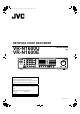
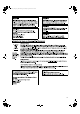
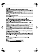
VR-N1600_Startup_EN_001B.book Page 1 Thursday, August 20, 2009 1:10 PM NETWORK VIDEO RECORDER VR-N1600U VR-N1600E STARTUP GUIDE (A) WARNING LIVE/BROWSE 㧝 㧞 㧟 㧠 SELECT 㧡 㧢 *1/' 㧣 㧤 PTZ/PRESET 㧥 ALARM OPERATE REV FWD HDD LOCK REC CONTROL FUNCTION SERIAL CANCEL ZOOM OUT ZOOM IN SEARCH KEY ALARM CLEAR REC/STOP STOP(PB) PLAY SKIP Powered by Milestone Please read the following before getting started: Thank you for purchasing this JVC product.
VR-N1600_Startup_EN_001B.
VR-N1600_Startup_EN_001B.
VR-N1600_Startup_EN_001B.
VR-N1600_Startup_EN_001B.
VR-N1600_Startup_EN_001B.
VR-N1600_Startup_EN_001B.
VR-N1600_Startup_EN_001B.
VR-N1600_Startup_EN_001B.
VR-N1600_Startup_EN_001B.book Page 2 Thursday, August 20, 2009 1:10 PM Getting Started Features Motion Detect Enables recording to start automatically when AmotionB is detected in the preset live image. You can also specify the detection area for each camera. Automatic detection of network cameras Reduces the hassle of complex camera registration procedures. Built-in large-capacity hard disk (500 GB) HDD expansion supported Addition of up to 500 GB (built-in), 2 TB x 2 units (external.
VR-N1600_Startup_EN_001B.book Page 3 Thursday, August 20, 2009 1:10 PM Contents Getting Started Features ............................................................................ 2 Contents ............................................................................ 3 Precautions for Proper Use of this Product ....................... 4 Part Names and Functions ................................................ 6 Mounting to a Rack .........................................................
VR-N1600_Startup_EN_001B.book Page 4 Thursday, August 20, 2009 1:10 PM Getting Started Precautions for Proper Use of this Product 䢇 Locations of Storage and Use 䢇 Do not store the unit at the following places. Doing so may cause the unit to malfunction or break down.
VR-N1600_Startup_EN_001B.book Page 5 Thursday, August 20, 2009 1:10 PM Precautions when Moving this Unit 䢇 Remove all connected cords before moving Turn off the power and remove the power plug before moving this unit. Failure to do so may cause damage on the cords, and result in fire or electric shock. 䢇 Moving of this unit or installation work is strictly prohibited when the power of this unit is on or immediately after the power is turned off (approximately 1 minute).
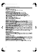
VR-N1600_Startup_EN_001B.book Page 6 Thursday, August 20, 2009 1:10 PM Getting Started Part Names and Functions Front S T R Q WARNING A B LIVE/BROWSE 㧝 㧞 㧟 㧠 SELECT 㧡 㧢 *1/' 㧣 㧤 PTZ/PRESET 㧥 ALARM OPERATE REV FWD O LOCK REC CONTROL FUNCTION SERIAL CANCEL ZOOM OUT ZOOM IN ENTER P HDD SEARCH KEY ALARM CLEAR REC/STOP STOP(PB) PLAY SKIP CD E F GHIJ K L M A [OPERATE] Button/Indicator Switches operation on or off.
VR-N1600_Startup_EN_001B.book Page 7 Thursday, August 20, 2009 1:10 PM When in the recording control mode, press and hold this button to exit the recording control mode. Memo : ● The manual recording mode executes recording from all cameras regardless of the settings in the [Camera Record Setting]. Recording is carried out in accordance with the frame rate selected in [Camera Record Setting]. L [STOP(PB)] Button Stops playback when you press this button in the playback mode.
VR-N1600_Startup_EN_001B.book Page 8 Thursday, August 20, 2009 1:10 PM Getting Started Part Names and Functions (continued) Rear Panel d POWER U ON OFF V W X YZ a b c U [POWER] switch a [SERIAL1 to 4] serial terminals 1 to 4 Switches the power on or off. For connecting the communication control terminals on a mouse (sold separately), flash memory (sold separately), UPS (sold separately) or additional disk drive (sold separately).
VR-N1600_Startup_EN_001B.book Page 9 Thursday, August 20, 2009 1:10 PM Rear I/O Terminals e fhjl n gikm o ON OFF p 䡵 Input ports 䡵 Output ports e [ALARM IN 1 to 8] alarm input terminals 1 to 8 j [COMMON] signal ground terminal Alarm recording is activated when signals are input to these terminals. This is a common ground terminal. Connect it to the signal ground terminal on the connected device. (This can be used when there are insufficient common ground terminals.
VR-N1600_Startup_EN_001B.book Page 10 Thursday, August 20, 2009 1:10 PM Getting Started Part Names and Functions (continued) Rear I/O Terminals Use the supplied rack mount bracket to mount VR-N1600U/E to the EIA rack. Terminal e[ALARM IN] Remarks 250 ms and above 250 ms and above Make Break Make Contact Input 1 Mount the rack mount bracket using screw (1) ● Use the 4 screws (M4 x 10 mm) supplied to fasten VR-N1600U/E at the two sides.
VR-N1600_Startup_EN_001B.book Page 11 Thursday, August 20, 2009 1:10 PM Preparation System Connection Example The following operations are possible with this system.
VR-N1600_Startup_EN_001B.book Page 12 Thursday, August 20, 2009 1:10 PM Preparation System Connection Example (continued) Note : ● Do not connect LAN1 to the internet. If the internet is busy or the relay equipment fails, you may not be able to save important camera images. To maintain full recording capacity, it is recommended that a dedicated network be used. Be sure to connect the LAN1 camera network to the same segment. (Do not use the address translation of NAT and NAPT etc. or a router.
VR-N1600_Startup_EN_001B.book Page 13 Thursday, August 20, 2009 1:10 PM 2 Check to ensure that the camera is detected Selecting a Language The [Language Setting] screen appears when you start up VR-N1600U/E for the first time. Select the language to use using the steps below. ● After the message disappears, a list of detected cameras is displayed. ● If all the cameras are not detected, press the [Auto Detect] button again.
VR-N1600_Startup_EN_001B.book Page 14 Thursday, August 20, 2009 1:10 PM Preparation During Initial Startup (continued) 5 Use the [SKIP] button to select [OK], followed by pressing the [16/ENTER] button ● The [Configure Device] screen appears. 10 Set the display rate of each camera such that the total display rate of all cameras does not exceed 80 ips (VR-N1600U/E) or 160 ips (VR-N1600U/E(A)). ● The default display rate is set at 8 ips.
VR-N1600_Startup_EN_001B.book Page 15 Thursday, August 20, 2009 1:10 PM Memo : C Use the [7/B] button to display the camera ● Use [SKIP] to move between the items. ● Use the [2/D] and [10/0/E] buttons to select the item to configure. ● To enter numeric characters, press the [SELECT] button to turn on the light of the [SELECT] indicator. Upon entering the numeric characters, press the [PTZ/ PRESET] button to turn on the light of the [PTZ/PRESET] indicator.
VR-N1600_Startup_EN_001B.book Page 16 Thursday, August 20, 2009 1:10 PM Basic Operation Viewing Live Images via Front Panel Control This section describes the procedures for viewing live images by using the front panel of VR-N1600U/E. Note : ● Do not switch the view frequently within a short time interval. ● When live images do not appear on VN-C625/VN-C655, set the password on the camera unit as well as VR-N1600U/E again.
VR-N1600_Startup_EN_001B.book Page 17 Thursday, August 20, 2009 1:10 PM 䡵 Pan/Tilt Memo : A Event indicator (Left: yellow) Lights up when events specified in the [Camera Record Setting] occur. The indicator appears black if event indication has not been specified for the camera in question, or if no specified event has occurred. B Motion indicator (Center: red) Lights up when motion is detected. keypad to the PTZ mode ● The [PTZ/PRESET] indicator lights up.
VR-N1600_Startup_EN_001B.book Page 18 Thursday, August 20, 2009 1:10 PM Basic Operation Playing Back Recorded Images via Front Panel Control This section describes the procedures for playing back recorded images using the front panel of VR-N1600U/E. Displaying the [Browse] Screen 1 Press the [LIVE/BROWSE] button when the Note : ● Do not switch the view frequently within a short time interval.
VR-N1600_Startup_EN_001B.book Page 19 Thursday, August 20, 2009 1:10 PM 䢇 Playing Back Adjusting the Playback Speed (Jog/Shuttle Playback) 1 Press the [PLAY] button ● Playback starts from the date/time indicated in [Master Time] of [Time Navigation]. ● Images are played back according to the angle of the shuttle dial (x1/20, x1/5, x1, x2, x5, x10, x20). [Master Time] area NVR Viewer You can adjust the playback speed by turning the jog dial/ shuttle dial on the front panel.
VR-N1600_Startup_EN_001B.book Page 20 Thursday, August 20, 2009 1:10 PM Others Troubleshooting Symptom Action Power cannot be turned on. Check to ensure that the power cable has been plugged in correctly. Check to ensure that the power switch on the rear panel is switched on. Camera is not automatically detected. Follow instructions in the camera’s [Instruction Manual] to check the IP address settings.
VR-N1600_Startup_EN_001B.
VR-N1600_Startup_EN_001B.
VR-N1600_Startup_EN_001B.
VR-N1600_Startup_EN_001B.