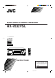
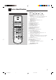
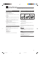
AUDIO/VIDEO CONTROL RECEIVER RX-7032VSL REMOTE CONTROL RX-7032V AUDIO/VIDEO CONTROL RECEIVER MASTER VOLUME CATV/DBS VCR DVD MULTI DVD TV/DBS VCR RM-SRX7032U TV AUDIO CD FM/AM TAPE/CDR ANALOG/DIGITAL INPUT SURROUND STANDBY SURROUND DSP SURR/DSP ANALOG OFF STANDBY/ON DSP ∗ DIRECT BASS BOOST FRONT•L EX/ES 1 2 ∗FRONT•R 3 MENU SPEAKERS ON/OFF 1 CD DISC TEST SURROUND/ DSP OFF 4 ∗CENTER ∗SUBWOOFER 5 6 ENTER MIDNIGHT 7/P MODE BASS BOOST DVD MULTI DVD VCR TV SOUND/DBS
Warnings, Cautions and Others Caution –– STANDBY/ON switch! Disconnect the mains plug to shut the power off completely. STANDBY/ON switch in any position does not disconThe nect the mains line. The power can be remote controlled. CAUTION To reduce the risk of electrical shocks, fire, etc.: 1. Do not remove screws, covers or cabinet. 2. Do not expose this appliance to rain or moisture. CAUTION • Do not block the ventilation openings or holes.
Table of Contents Introduction ................................................ 2 Adjusting Sound ........................................ 29 Parts Identification ...................................... 3 Basic Setting Items ................................................................... 29 Basic Procedure ........................................................................ 29 Adjusting the Equalization Patterns ................................... 30 Adjusting the Speaker Output Levels ...........
Introduction We would like to thank you for purchasing one of our JVC products. Before operating this unit, read this manual carefully and thoroughly to obtain the best possible performance from your unit, and retain this manual for future reference. Features Precautions Compatible with various audio formats including DTS 96/24 RX-7032VSL allows you to enjoy a newly introduced audio format such as Dolby Digital EX, Dolby Pro Logic II, DTS-ES, DTS Neo:6, and DTS 96/24.
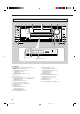
Parts Identification 1 Remote Control RM-SRX7032U REMOTE CONTROL 1 2 3 2 CATV/DBS VCR TV AUDIO DVD MULTI DVD CD FM/AM TV/DBS VCR TAPE/CDR ANALOG/DIGITAL INPUT SURROUND DSP EX/ES BASS BOOST CD DISC TEST SURR/DSP ANALOG OFF 1 DIRECT 2 3 e r 3 MENU 4 4 ∗CENTER∗SUBWOOFER 5 6 ENTER 5 6 7 8 9 p q w MIDNIGHT CATV/DBS CONTROL 10/0 0 +10 RETURN FM MODE 100+ + + + ∗ CH/ LEVEL TV VOL − − TAPE/CDR VCR CONTROL CONTROL /REW REC PAUSE t 9 ∗DIGITAL EQ ∗SURR BACK SOUN
Front Panel 2 1 3 4 5 RX-7032V 6 8 7 AUDIO/VIDEO CONTROL RECEIVER MASTER VOLUME SURROUND STANDBY DSP STANDBY/ON SPEAKERS ON/OFF SURROUND/ DSP OFF 1 BASS BOOST 2 DVD MULTI DVD VCR TV SOUND/DBS CD TAPE/CDR FM AM SUBWOOFER OUT ON/OFF SETTING ADJUST ANALOG DIRECT MULTI JOG QUICK SPEAKER SETUP EXIT PUSH – OPEN PUSH SET PHONES 9 y ui p EX / ES MIDNIGHT MODE INPUT ANALOG INPUT DIGITAL FM/AM TUNING Display Window o FM/AM PRESET FM MODE MEMORY TUNER CONTROL INPUT ATT qw e
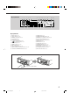
Display Window 3 1 2 4 5 DUAL ANALOG DIGITAL AUTO 96/24 L C R SUBWFR LFE LS S 67 MULTI 89 0 - = ~! @ TUNED STEREO AUTO MUTING ONE TOUCH OPERATION SLEEP LINEAR PCM PRO LOGIC NEO:6 VIRTUAL SB MIDNIGHT MODE DIGITAL EQ DSP 3D - PHONIC DIGITAL HEADPHONE SPEAKERS 1 2 BASS BOOST RS INPUT ATT VOLUME SB # $ ^ % & * () _ + Display Window 1 2 3 4 5 6 7 8 9 0 = DUAL indicator (33) ANALOG indicator (18) DIGITAL AUTO indicator (18) 96/24 indicator (33) MULTI indicator (38) PRO LOGIC indic
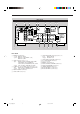
Rear Panel 1 2 3 VIDEO AUDIO DIGITAL IN SUBWOOFER CENTER RIGHT VIDEO LEFT SUBWOOFER OUT S-VIDEO DVD IN DVD IN TV SOUND DBS IN RIGHT MONITOR OUT Y CAUTION : SPEAKER IMPEDANCE 8 IN (PLAY) FM 75 OUT (REC) TAPE CDR IN (PLAY) PCM/ DOLBY DIGITAL / DTS CD IN DIGITAL OUT MONITOR OUT AV COMPULINK- DBS IN OUT (REC) DIGITAL 4 (CDR) (SYNCHRO) AM LOOP VCR DIGITAL 3 (TV) 8 9 COMPU LINK-4 COMPONENT VIDEO AM EXT LEFT DIGITAL 2 (CD) 7 DVD IN ANTENNA FRONT SURR DIGITAL 1 (DVD) (REAR)
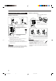
Getting Started This section explains how to connect audio/video components and speakers to the receiver, and how to connect the power supply. Before Installation General Precautions • Be sure your hands are dry. • Turn the power off to all components. • Read the manuals supplied with the components you are going to connect. Putting Batteries in the Remote Control Before using the remote control, insert the two supplied batteries first.
Connecting the FM and AM Antennas AM Antenna Connections Turn the loop until you have the best reception. FM Antenna Connections A NN TE AN A NN TE AN ANTENNA B A AM EXT AM LOOP 75 FMAXIAL AM Loop Antenna (supplied) 75 FMAXIAL CO CO Snap the tabs on the loop into the slots of the base to assemble the AM loop. ANTENNA FM 75 FM Antenna (supplied) AM EXT Extend the supplied FM antenna horizontally.
Speaker layout Connecting the Speakers You can connect the following speakers: • Two pairs of front speakers to produce normal stereo sound. • One pair of surround speakers to enjoy the surround effect. • One surround back speaker or one pair of surround back speakers to enjoy to produce more effective surround effect. • One center speaker to emphasize human voices. • One subwoofer to enhance the bass. Ideal speaker layout varies depending on the conditions of your listening room.
CAUTION : SPEAKER IMPEDANCE 8 Front speakers 1 Right / Left Center speaker Surround back speakers* Right / Left Front speakers 2 Right / Left 16 + + CAUTION : SPEAKER IMPEDANCE SINGLE USE See Instruction Manual For Connection + + – – 1 OR 2 : 8 16 1 AND 2 : 16 32 – – RIGHT LEFT RIGHT SURROUND BACK SPEAKERS LEFT RIGHT SURROUND SPEAKERS Surround speakers Right / Left * When using only one surround back speaker, connect the ª cord to the RIGHT ª terminal and the · cord to the LEFT ·
Connecting Audio/Video Components When connecting individual components, refer also to the manuals supplied with them. Analog Connections Cassette deck To listen to the sound after connection, press TAPE/CDR. You can connect either a cassette deck or a CD recorder to the TAPE/CDR jacks. When connecting an CD recorder to the TAPE/ CDR jacks, see below.
Video component connections TV and/or DBS tuner Use the cables with RCA pin plugs (not supplied). Connect the white plug to the audio left jack, the red plug to the audio right jack, and the yellow plug to the video jack. • If your video components have S-video (Y/C-separation) and/or component video (Y, PB, PR) terminals, connect them using an Svideo cable (not supplied) and/or component video cable (not supplied).
DVD player • When you connect a DVD player with stereo output jacks: To listen to the sound after connection, press DVD. • When you connect a DVD player with its analog discrete output (5.1-channel reproduction) jacks: To listen to the sound after connection, press DVD MULTI.
Digital Connections Digital output terminal This receiver is equipped with four DIGITAL IN terminals—one digital coaxial terminal and three digital optical terminals—and one DIGITAL OUT (optical) terminal on the rear. You can connect any digital components which have an optical digital input terminal.
Basic Operations The following operations are commonly used when you play any sound sources. Operations hereafter will be explained using the buttons on the front panel. You can also use the buttons on the remote control for the same functions if they have the same and similar names/marks. Selecting the Source to Play Daily Operational Procedure RX-7032V RX-7032V 1 AUDIO/VIDEO CONTROL RECEIVER AUDIO/VIDEO CONTROL RECEIVER 3 4 2 Press one of the source selection buttons.
Speaker and signal indicators on the display By checking the following indicators, you can easily confirm which speakers you are activating and which signals are coming into this receiver. Speaker indicators L C Signal indicators R L C SUBWFR LS R LFE RS LS S Selecting different sources for picture and sound While watching pictures from a video source, you can listen to sound of an audio source.
Selecting the Front Speakers Remote NOT When you have connected two pairs of the front speakers, you can select which to use. RX-7032V AUDIO/VIDEO CONTROL RECEIVER Activating and Adjusting the Subwoofer Sound You can cancel the subwoofer sound even though you have connected a subwoofer and have set “SUB WOOFER” to “YES” (see page 25). This is useful when enjoying surround sound at night.
2. Press INPUT DIGITAL (or ANALOG/DIGITAL INPUT on the remote control) to select “DGTL AUTO.” Setting the Dynamic Range You can enjoy a powerful sound at night using the Midnight Mode. The DIGITAL AUTO indicator lights up on the display. DIGITAL AUTO L C LS RX-7032V AUDIO/VIDEO CONTROL RECEIVER R SUBWFR LFE SPEAKERS 1 DIGITAL RS VOLUME • When selecting “DGTL AUTO,” the following indicators indicate the digital signal format of the incoming signal.
Turning Analog Direct On and Off You can enjoy the sound closer to the original source by overriding the sound adjustments such as speaker output level adjustments (see page 30), Digital Equalization (see page 30), Surround and DSP modes (see pages 32 to 37), Bass Boost (see page 20) and Midnight Mode (see page 18). You can only adjust the volume level while Analog Direct is in use. • Once you have made adjustment, it is memorized for each analog source.
The following basic operations are possible only using the remote control. Using the Sleep Timer Using the Sleep Timer, you can fall asleep while listening to music. When the shut-off time comes, the receiver turns off automatically. BASS BOOST 1 2 3 4 5 6 7/P 8 9 10/0 0 +10 Reinforcing the Bass Press SLEEP repeatedly.
Receiving Radio Broadcasts You can browse through all the stations or use the preset function to go immediately to a particular station. Tuning in to Stations Manually RX-7032V Using Preset Tuning AUDIO/VIDEO CONTROL RECEIVER RX-7032V 1. Press FM or AM to select the band. The last received station of the selected band is tuned in. ANALOG L R SPEAKERS 1 VOLUME 2. Press FM/AM TUNING 5 or ∞ repeatedly until you find the frequency you want. • Pressing FM/AM TUNING 5 increases the frequency.
To tune in a preset station Selecting the FM Reception Mode On the front panel: RX-7032V RX-7032V AUDIO/VIDEO CONTROL RECEIVER AUDIO/VIDEO CONTROL RECEIVER 1. Press FM or AM to select the band. The last received station of the selected band is tuned in. 2. Press FM/AM PRESET 5 or ∞ until you find the channel you want. • Pressing FM/AM PRESET 5 increases the number. • Pressing FM/AM PRESET ∞ decreases the number.
Basic Settings Some of the following settings are required after connecting and positioning your speakers while others will make operations easier. You can use QUICK SPEAKER SETUP to easily set up your speaker configuration. Setting the Speakers Configuration Remote NOT Quick Speaker Setup helps you to easily and quickly register the speaker size and speaker distance according to your listening room to create the best possible surround effect. • You can also register each speaker’s information manually.
Speakers (channels) number and size You can find how each of the speaker size is defined according to the number of connected speakers (speaker channel (CH) number) you select. In the following tables, “L” stands for “left front speaker,” “R” for “right front speaker,” “C” for “center speaker,” “LS” for “left surround speaker,” “RS” for “right surround speaker,” “SB” for “surround back speaker,” and “SUBWFR” for “subwoofer.” • Subwoofer is counted as 0.1 channel.
Basic Procedure : shows the initial setting in the following tables. RX-7032V AUDIO/VIDEO CONTROL RECEIVER Setting the Speakers Before you start, remember... There is a time limit in doing the following steps. If the setting is canceled before you finish, start from step 1 again. To obtain the best possible surround effect from the Surround and DSP modes, register the setting about the speaker arrangement after all connections are completed.
7 Surround back speakers quantity—SBACK OUT Select the number of the surround back speakers connected. C 1SPK: Select this to use 1 surround back speaker. L R 2SPK: Select this to use 2 surround back speakers. 3.3 m (11 ft) 3.0 m (10 ft) 2.7 m (9 ft) Note: If you have selected “NONE” for the surround back speakers (see page 25), this setting is not available.
Setting the Bass Sounds 7 Low frequency effect attenuator—LFE ATTENUATE You can adjust subwoofer and bass sounds precisely according to your preference. If the bass sound is distorted while playing back software encoded with Dolby Digital or DTS, set the LFE level to eliminate distortion. 7 Subwoofer output—S WFR OUTPUT Select one of the following: You can select the type of the signal which can be transmitted through the subwoofer.
Setting the Digital Input Terminals Memorizing the Volume Level for Each Source When you use the digital input terminals, register which components you have connected to the digital input terminals. This unit memorizes some settings separately for each source. In addition, you can store the volume level for each source with the other memorized settings—One Touch Operation. 7 Digital coaxial terminal—DGTL IN COAX Set the component connected to the digital coaxial terminal (DIGITAL IN 1).
Adjusting Sound You can make sound adjustment to your preference after completing basic setting. Basic Setting Items Basic Procedure On the following pages, you can adjust the items listed below: • You can adjust only the items applicable to the current sound mode. • If Analog Direct is in use, you cannot make any sound adjustments. Items To do Adjust equalizer pattern. 30 SUBWFR LVL Adjust the subwoofer output level. 30 FRONT L LVL Adjust the left front speaker output level.
Adjusting the Equalization Patterns Adjusting the Speaker Output Levels You can adjust the equalization patterns to your preference. • Once you have made adjustment, it is memorized for each source. You can adjust the speaker output levels. The test tone comes out of each speaker except subwoofer to check the output level balance when using the Surround mode. • Once you have made an adjustment, it is memorized for each source.
You can also use the remote control for adjusting the speaker output level. When using the remote control, you can make an adjustment while listening to test tone. 1 2 3 4 5 6 7/P 8 9 10/0 0 +10 Adjusting the Sound Parameters for the Surround and DSP Modes You can adjust the Surround and DSP sound parameters to your preference. • When center speaker is set to “NONE,” CTR TONE, CNTR WIDTH, and CNTR GAIN are not available.
Using the Surround Modes This unit activates a variety of Surround modes automatically. The basic settings and adjustments stored (see pages 23 to 31) are applied. Reproducing Theater Ambience Introducing the Surround Modes In a movie theater, many speakers are located on the walls to reproduce impressive multi-surround sounds, reaching you from all directions. With these many speakers, sound localization and sound movement can be expressed.
Dolby Pro Logic II DTS 96/24 Dolby Pro Logic II is a multi-channel playback format to convert 2channel software into 5-channel (plus subwoofer). The matrix-based conversion method used for Dolby Pro Logic II makes no limitation for the cutoff frequency of the surround treble and enables stereo surround sound. • This receiver provides two types of Dolby Pro Logic II modes— Pro Logic II Movie (PLII MOVIE) and Pro Logic II Music (PLII MUSIC).
Surround Modes Applicable to the Various Software Available Surround modes vary depending on the speaker settings and the incoming signals. The table below shows the relation of the Surround modes and the incoming signals (with the surround back speakers and EX/ES setting). • The numbers inside the parentheses following the incoming signal type indicate the number of the front channels and that of the surround channels.
Activating the Surround Modes Activating the Surround Modes Available Surround modes vary depending on the speaker settings and the incoming signals. (See page 32.) RX-7032V AUDIO/VIDEO CONTROL RECEIVER Activating one of the Surround modes for a source automatically recalls the memorized settings and adjustments (see pages 23 to 31.) You can also use the buttons on the remote control for the same functions. Activating the EX/ES setting For multi-channel digital software, you can activate the EX/ES (7.
Using the DSP Modes This unit activates a variety of DSP modes automatically. The basic settings and adjustments stored (see pages 23 to 31) are applied automatically. Reproducing the Sound Field The sound heard in a concert hall, club, etc. consists of direct sound and indirect sound—early reflections and reflections from behind. Direct sounds reach the listener directly without any reflection. On the other hand, indirect sounds are delayed by the distances of the ceiling and walls.
All Channel Stereo mode This mode can reproduce a larger stereo sound field using all the connected (and activated) speakers. This mode cannot be used without activating the surround speakers. • If the front speakers are deactivated, “All Channel Stereo” cannot be selected. Activating the DSP Modes Activating one of the DSP modes for a source automatically recalls the memorized settings and adjustments (see pages 23 to 31.) You can also use the buttons on the remote control for the same functions.
Using the DVD MULTI Playback Mode This receiver provides the DVD MULTI playback mode for reproducing the analog discrete output mode of the DVD player. Activating the DVD MULTI Playback Mode Connection diagram RX-7032V AUDIO/VIDEO CONTROL RECEIVER COMPONENT VIDEO DVD IN SUBWOOFER CENTER RIGHT 1. Press DVD MULTI so that “DVD MULTI” appears on the display. VIDEO AUDIO VIDEO LEFT S-VIDEO DVD IN DVD IN The MULTI indicator also lights up.
COMPU LINK Remote Control System The COMPU LINK remote control system allows you to operate JVC’s audio components through the remote sensor on the receiver. To use this remote control system, you need to connect JVC’s audio components through the COMPU LINK (SYNCHRO) jacks (see below) in addition to the connections using cables with RCA pin plugs (see page 10). • Make sure that the AC power cords of these components are unplugged before connection.
AV COMPU LINK Remote Control System The AV COMPU LINK remote control system allows you to operate JVC’s video components (TV, VCR, and DVD player) through the receiver. This receiver is equipped with the AV COMPU LINK-III, which adds a function to the previous version in order to operate JVC’s video components through the video components terminals. To use this remote control system, connect the video components you want to operate, following the diagrams below and the procedure on the next page.
1. If you have already plugged your VCR , DVD player, TV and this receiver into the AC outlets, unplug their AC power cords first. 2. Connect your VCR, DVD player, TV and this receiver, using the cables with the monaural miniplugs (not supplied). • See “CONNECTIONS 1” on the previous page. 3. Connect the audio input/output jacks on VCR, DVD player, TV and this receiver using the cables with RCA pin plugs. • See pages 12 and 13. 4.
Operating JVC’s Audio/Video Components You can operate JVC’s audio and video components with this receiver’s remote control, since control signals for JVC’s components are preset in the remote control.
CD changer CD recorder After pressing CD DISC, you can perform the following operations on a CD changer: 3: 4: Start playing. Return to the beginning of the current (or previous) track. ¢: Skip to the beginning of the next track. 7: Stop playing or recording. 8: Pause playing. To resume, press 3. 1 – 6, 7/P: Select the number of a disc installed in a CD changer. After pressing CD, you can perform the following operations on a CD changer: 1 – 10/0, +10: Select a track number directly.
Operating Video Components DVD player After pressing DVD or DVD MULTI, you can perform the following operations on a DVD player: IMPORTANT: To operate JVC’s video components using the supplied remote control: • You need to connect JVC’s video components through the AV COMPU LINK jacks (see page 39) in addition to the connections using cables with RCA pin plugs (see pages 11 and 12). • Some JVC’s VCRs can accept two types of the control signals— remote code “A” and “B.
Operating Other Manufacturers’ Video Equipment This remote control supplied with the receiver can transmit control signals for other manufacturers’ TVs, CATV converters, DBS tuners, VCRs and DVD players. When operating the other manufacturers’ components, refer also to the manuals supplied with them. • After replacing batteries for the remote control, you need to set the manufactures’ codes again. To change the transmittable signals for operating another manufacturer’s TV 1. Press and hold TV . 2.
To change the transmittable signals for operating a CATV converter or DBS tuner 1. Press and hold CATV/DBS . 2. Press CATV/DBS CONTROL. 3 Enter a manufacturer’s code using buttons 1 – 9, and 0. See the list on the right column to find the code. 4. Release CATV/DBS . The following buttons can be used for operating a CATV converter and DBS tuner: CATV/DBS : Turn on and off a CATV converter or DBS tuner.
To change the transmittable signals for operating another manufacturer’s VCR For VCR 1. Press and hold VCR . 2. Press VCR. 3. Enter manufacturer’s code using buttons 1–9, and 0. See the list on the right column to find the code. 4. Release VCR . The following buttons can be used for operating a VCR: VCR : Turn on and off a VCR. After pressing VCR, you can perform the following operations on a VCR: CH +/–: Change the TV channels on a VCR. 1 – 10/0, 0, 100+ (+10): Select the TV channels.
To change the transmittable signals for operating another manufacturer’s DVD player 1. Press and hold AUDIO Manufacturer . 2 Press DVD. 3. Enter a manufacturer’s code using buttons 1–9, and 0. See the list on the right column to find the code. 4. Release AUDIO . After pressing DVD or DVD MULTI, you can perform the following operations on a DVD player: 3: 4: ¢: 7: 8: For DVD player Start playing. Return to the beginning of the current (or previous) chapter. Skip to the beginning of the next chapter.
Troubleshooting Use this chart to help you solve daily operational problems. If there is any problem you cannot solve, contact your JVC’s service center. PROBLEM SOLUTION POSSIBLE CAUSE The display does not light up. The power cord is not plugged in. Plug the power cord into an AC outlet. No sound from speakers. Speaker signal cables are not connected. Check speaker wiring and reconnect if necessary. (See pages 9 and 10.) The SPEAKERS ON/OFF 1 and SPEAKERS ON/OFF 2 buttons are not set correctly.
Specifications Amplifier Output Power At Stereo operation Front ch: 100 W per channel, min. RMS, driven into 8 Ω, 1 kHz, with no more than 0.8% total harmonic distortion. (IEC268-3/DIN) At Surround operation: Front ch: 100 W per channel, min. RMS, driven into 8 Ω at 1 kHz, with no more than 0.8% total harmonic distortion. Center ch: 100 W, min. RMS, driven into 8 Ω at 1 kHz, with no more than 0.8% total harmonic distortion. Surround ch: 100 W per channel, min.
RX-7032VSL AUDIO/VIDEO CONTROL RECEIVER VICTOR COMPANY OF JAPAN, LIMITED EN © 2003 VICTOR COMPANY OF JAPAN, LIMITED COVER_7032[A]3.pm6 2 0503AIMMDWJEIN 03.5.