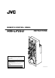
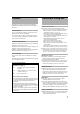
REMOTE CONTROL PANEL RM-LP25U INSTRUCTIONS OPE RAT E LOC PARK T 1 SCE 2 NE FIL 3 NOR MA OFF L BAR PAR T 1 /1 0 1 /1 2 0 0 L FUL E 4 1/25 SPE SHU TT 1/50 ER 0 0 0dB 3dB -3 d 1/10 6dB LEV 1/20 B 12d ALC LOL EL GAM VAR R NUA L WH ITE PAIN T EP OIN IT P R E E BAL ANC SET EM FAW ODE B AW PAIN AW AUT PAIN OVE IRIS PRE SET CAL FUL TAL L LY Enter below the Serial No. which is located on the body. Retain this information for future reference. Model No. Serial No.
Getting Started FOR USA These are general IMPORTANT SAFEGUARDS and certain items may not apply to all appliances. IMPORTANT SAFEGUARDS 1. 2. 3. 4. Read all of these instructions. Save these instructions for later use. All warnings on the product and in the operating instructions should be adhered to. Unplug this appliance system from the wall outlet before cleaning. Do not use liquid cleaners or aerosol cleaners. Use a damp cloth for cleaning. 5.
Safety Precautions INFORMATION (FOR CANADA) RENSEIGNEMENT (POUR CANADA) This Class A digital apparatus complies with Canadian ICES-003. FOR USA AND CANADA Cet appareil num rique de la Classe A est conforme á la norme NMB-003 du Canada. CAUTION RISK OF ELECTRIC SHOCK DO NOT OPEN CAUTION: TO REDUCE THE RISK OF ELECTRIC SHOCK. DO NOT REMOVE COVER (OR BACK). NO USER-SERVICEABLE PARTSINSIDE. REFER SERVICING TO QUALIFIED SERVICE PERSONNEL.
Getting Started Safety Precautions (continued) Information for Users on Disposal of Old Equipment [European Union] Attention: FOR EUROPE This equipment is in conformity with the provisions and protection requirements of the corresponding European Directives. This equipment is designed for professional video appliances and can be used in the following environments: R Controlled EMC environment (for example, purpose-built broadcasting or recording studio), and rural outdoors environments.
Features This product is a remote control panel for controlling HD CAMERA RECORDER(GY-HD250/GY-HD251/GY-HD200/ GY-HD201). Scene File Feature You can assign different settings to each of the five Scene File buttons and save them accordingly. This is useful at job sites where speed is required, as you can recall the settings according to the shooting conditions by pressing the relevant button.
Getting Started Table of Contents Getting Started Safety Precautions ............................................................. 3 Features ............................................................................. 5 Precautions During Use ..................................................... 5 Table of Contents ............................................................... 6 Names and Functions of Parts ........................................... 7 Control Panel ....................................
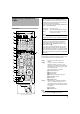
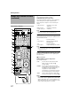
Names and Functions of Parts Indicator light: For features that make use of self-illuminating buttons, features available on the connected camera are checked and displayed during communication to verify connection with the camera (initial communication). T However, this excludes the [OPERATE], [SCENE FILE 1 to 5], and [PREVIEW] buttons. Control Panel Orange light on : Currently selected.
Getting Started Names and Functions of Parts (continued) B [OPERATE]Operate Button and Indicator Light ON (Orange light on) : Control of the camera using this unit is enabled. OFF (Light off) : Control of the camera using this unit is disabled. C [SCENE FILE 1 to 5]Scene File Button and Indicator Light(A 19 page) Control Panel (continued) For storing the scene file data and loading/clearing the preset scene file data.
[LEVEL] level adjustment knob: For adjusting the gamma level. LEVEL Decreases the reproducibility of dark areas. GAMMA Enhances the reproducibility of dark areas. Note: ● The feature is not available on the camera if the light of the corresponding button is not lit. Control using this unit is disabled in this case. Lights up in green : Auto white is successfully completed. Blinks in orange B Lights up in green : Auto white is abnormally terminated.
Getting Started Names and Functions of Parts (continued) J Black Balance Control Unit (A 18 page) For specifying the black balance settings. 䢇 [AUTO BLACK] Auto Black button: Pressing this button when it lights up in green switches the color to orange and starts up the auto black feature. After the adjustment is complete, the result is indicated by the indicator. Lights up in green : Auto black is successfully completed. Blinks in orange B Lights up in green : Auto black is abnormally terminated.
䢇 [PRESET LEVEL] Preset Level setting knob M [IRIS/AUTO IRIS LEVEL] Iris/Auto Iris Setting Lever For setting the center value of the 4-f/stops (approximately) range when the [IRIS MODE] switch is set to APRESETB. The function varies according to the setting of [IRIS MODE]. ● Example Setting of [IRIS MODE] Center Value FULL For adjusting the iris level. (CLOSE-OPEN) PRESET For adjusting the iris level of any 4f/stops (approximately) range. (CLOSE-OPEN) AUTO For adjusting the auto iris level.
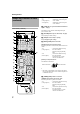
Getting Started Names and Functions of Parts (continued) Control Panel (continued) A OPERATE LOCK BARS PART B OFF S FULL SCENE FILE C 1 2 3 D F 1/1000 1/20 : When you release the button, the indicator light turns off, and the tally lamp at the camera's end stops blinking. Blinking orange light : Upon receiving a call (CALL ON signal) from the camera, the indicator starts to blink in orange.
䢇 [KNEE POINT] Knee Point setting knob: For adjusting the knee point setting manually when the auto knee button is turned AOFFB. Decreases the knee point. KNEE POINT Rear/Side of Remote Control Panel U V T Increases the knee point Note: ● The feature is not available on the camera if the light of the corresponding button is not lit. Control using this unit is disabled in this case.
Operation Exemplary System Setup Connection: Connect the remote control unit cable to the REMOTE terminal. To reduce the emission of unwanted radio waves, be sure to attach the provided clamp filter as shown in the figure below. ● Attach the clamp filter as close to this device as possible, as shown in the figure. 1 Set up by connecting this product to GY-HD250 or GY-HD200. ● Connect according to the instruction manual of the devices in use, and set accordingly.
䡵 [SPEED] Variable Scan Speed setting knob ] Shutter Settings This is the knob for setting the shutter speed when the [VARIABLE] shutter speed button is selected. The setting range varies according to the connected camera. For specifying the shutter settings. 1 Press any of the shutter speed buttons. ● The selected shutter speed button lights up in orange, and the speed button that was previously selected turns green.
Operation 䡵 [LEVEL] Variable Gain Selection Button Gain Settings This is the knob for setting the gain value when the [VARIABLE] gain button is selected. The setting range varies according to the connected camera. Memo: For specifying the gain settings. 1 Press any of the gain value buttons. ● The selected gain value button lights up in orange, and the gain value button that was previously selected turns green.
White Balance Adjustment 3 Fine-tune the R- and B-gain values whenever necessary. ● Press [WHITE PAINT], and use the [WHITE PAINT R/B] knob to fine-tune the R- and B-gain values. For specifying the white balance settings. BLACK COMPRESS Setup: ● Set the [BARS] button to AOFFB. ● Place a white object near the center of the screen under the same lighting conditions as the target subject and zoom in to fill the screen with white. ● Set the optical filter of the camera according to the color temperature.
Operation Black Balance Adjustment Manual Adjustment 䡵 Black Balance 1 Press [BLACK PAINT]. For specifying the black balance settings. Setup: ● Set the [BARS] button to AOFFB. ● The [BLACK PAINT] indicator lights up in orange. 2 Adjust the black balance value manually using the [BLACK PAINT R/B] knob. R WHITE PAINT B PAINT AUTO WHITE PAINT AUTO BLACK Automatic Adjustment Lit 1 Press [AUTO BLACK] (push once). ● The [AUTO BLACK] indicator lights up in orange.
2 Press and hold the [SCENE FILE] button where Scene File the settings are to be stored for at least two seconds. ● The [SCENE FILE] button and the [OPERATE] button blink in orange, and storing starts. You can save various settings of this product according to the different shooting conditions as scene files. You can save up to five different scene files, and recall them simply by pressing the button. You can also identify the status of the scene files based on the indicator light of the button.
Operation 3 Loading is complete. Scene File (continued) ● The [OPERATE] button switches back to a solid orange light, and the buttons and indicators of all other features are also lit according to their preset status.
3 Clearing is complete. ● The [OPERATE] button switches back to a solid orange light, and the light of the [SCENE FILE] button for which settings have been deleted is turned off. List of Supported Features in Scene Files The following are functions that can be stored in scene files. Storage in scene file OPERATE LOCK BARS PART Lit OFF 2 3 Function Function Description FULL SCENE FILE 1 No.
Operation Adjustment of Indicator's Brightness The brightness of the indicator light on the control panel can be adjusted in five levels. Indicators for which brightness cannot be adjusted: ● [CALL] button ● [PREVIEW] button ● [TALLY] indicator 1 Set the [LOCK] switch to AOFFB.
Tally Input Terminal PREVIEW Output Terminal 䡵 Input Conditions 䡵 Output Conditions ● No-voltage relay contact a input, or open collector input (contact a: AOpenB at normal times, and AClosedB during Tally) ● 10 kK for internal, connected to 5 V power ● Input signals can be set using the DIP switch (A 24 page ADIP Switch 6B) Tally Input Terminal RM-LP25U Switcher Example (1) DC 5 V R TALLY IN (PGM,PVM) OUT Switcher Example (1) PREVIEW Output Terminal DC 5 V OUT IN GND GND GND Tally Input Equ
Operation Setting Selection DIP Switch 䡵 DIP Switch 3 For setting the [IRIS MODE] when AALCB is selected for the [GAIN] button. Function You can partially switch the settings of features (factory settings). All switches are set to AOFFB in the factory settings. Setting For setting whether the iris mode is to be forcibly switched to AAUTOB when AALCB is selected for the [GAIN] button. OFF Forcibly set to AAUTOB. ON Not forcibly set to AAUTOB. (Iris mode complies with the switch status.
Operable Features No. Function GY-HD250 GY-HD200 GY-HD251 GY-HD201 X: Enabled, ⳯: Disabled 18dB X X ALC X X LOLUX ⳯ ⳯ ⳯ ⳯ X X X X XT XT XT XT NORMAL X X STRETCH X X COMPRESS X X X X X X X X AW A X X AW B X X WHITE PAINT X X AUTO WHITE X X GAIN Features that can be controlled using this product vary according to the camera connected. Features that are enabled/disabled when GY-HD250/GYHD251/GY-HD200/GY-HD201 are connected are shown below.
Operation Operation of Connected Camera When RM-LP25U is connected to a camera, all features that are available on RM-LP25U can only be controlled via RMLP25U, and control of these features using the camera is disabled. Switches on the camera that are disabled, as well as disabled menu items are as follows. Remote Connector Specifications 䡵 Remote Cable Manufactured by Hosiden Corporation (Length: 5 m) 䡵 Switches that are disabled ● ● ● ● ● GAIN SHUTTERT WHT.
Others Troubleshooting Troubleshooting Power does not turn ON/OFF upon pressing the Operate button. Check Point Reference Page ● Is the Operation Lock switch set to APARTB or AFULLB? Set to AOFFB. A 7 page ● Are the cables properly connected? A 14 page ● Is the power of the connected camera functioning normally? Unable to select A-3dBB or A6dBB of the gain selection button when they are pressed.
RM-LP25U REMOTE CONTROL PANEL © 2007 Victor Company of Japan, Limited LST0594-001A