R RM-P210 REMOTE CONTROL UNIT INTRODUCTION CONNECTION PREPARATIONS AND MAIN FUNCTIONS CAMERA ADJUSTMENTS REMOTE CONTROL UNIT RM-P210 INSTRUCTIONS MENU OPERATION GENERAL REMOTE CONTROL UNIT RM-P210 TALLY CALL FULL AUTO F1 F3 MENU/SHUTTER GAIN SHUTTER BARS F2 F4 MENU SHUTTER VARIABLE PUSH-ON PUSH-ON PAINT WHITE W.
IMPORTANT SAFEGUARDS 1. 2. 3. 4. 5. 6. 7. 8. 9. 10. 11. 12. 13. 14. 15. 16. 17. 18. 19. 2 Read all of these instructions. Save these instructions for later use. All warnings on the product and in the operating instructions should be adhered to. Unplug this appliance system from the wall outlet before cleaning. Do not use liquid cleaners or aerosol cleaners. Use a damp cloth for cleaning. Do not use attachments not recommended by the appliance manufacturer as they may cause hazards.
SAFETY PRECAUTIONS CAUTION RISK OF ELECTRIC SHOCK DO NOT OPEN CAUTION : TO REDUCE THE RISK OF ELECTRIC SHOCK, DO NOT REMOVE COVER (OR BACK). NO USER SERVICEABLE PARTS INSIDE. REFER SERVICING TO QUALIFIED SERVICE PERSONNEL. The lightning flash with arrowhead symbol, within an equilateral triangle is intended to alert the user to the presence of uninsulated “dangerous voltage” within the product's enclosure that may be of sufficient magnitude to constitute a risk of electric shock to persons.
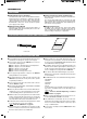
INTRODUCTION FEATURES Cable extension up to 100 meters The cable between the camera and the RM-P210 Remote Control Unit can be extended up to 100 meters using the optional VC-P110 series camera cables. Even when the cable is extended, the power to the camera is supplied from the RM-P210 so there is no need to provide a separate power supply for the camera. Genlock Function Built In Genlocking is possible using a composite video (VBS) or a black burst (BB) signal.
INTRODUCTION CONTROLS, CONNECTORS AND INDICATORS Front panel 1 2 34 56 7 8 9 0 ! REMOTE CONTROL UNIT RM-P210 TALLY CALL FULL AUTO F1 F3 MENU/SHUTTER GAIN SHUTTER BARS F2 F4 MENU SHUTTER VARIABLE PUSH-ON PUSH-ON PAINT WHITE W.BAL HIGH B MID LOW I A R B POWER IRIS MASTER BLACK AUTO STEP PRESET AUTO MANU GAIN O INTERCOM LEVEL ¤⁄ DOWN ) ( 1 Intercom jack Connect the intercom headset to this jack. REF. : “Intercom” on page 14.
INTRODUCTION CONTROLS, CONNECTORS AND INDICATORS (CONTINUED) ! [POWER] switch Press this switch to turn the power ON and OFF. @ [WHITE - W.BAL B/A/PRESET] switch This switch switches the white balance control setting between the value stored in Memory B (AUTO 2), that stored in Memory A (AUTO 1) and the PRESET value (3200K).
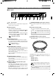
INTRODUCTION CONTROLS, CONNECTORS AND INDICATORS (CONTINUED) Rear panel TALLY PGM PVW INTERCOM C H C AUX VIDEO INPUT GENLOCK INPUT VIDEO OUTPUT R/R-Y G G/Y COMPOSITE VIDEO RTS 1 2 3 Y/C OUT B/B-Y CAMERA CABLE 4 1 [AC ` IN] connector Connect this socket to a commercial power supply outlet using the power cord provided. 2 [TALLY] terminals These terminals input the tally signals.
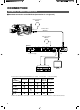
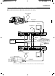
CONNECTION EXAMPLE OF BASIC CONNECTION Standard connection of the RM-P210 (Connection of a single unit) Intercom headset KA-310 OPERATE/WARNING LIGHT RESET FILTER ALARM 1 3200k 2 5600k+1/8ND 3 5600k+1/64ND SHUTTER STATUS RM VTR COUNTER CTL TC UB CH-1 LEVEL BLACK CH-2 CH-1 Camera cable VC-P110 CH-2 AUTO MANUAL FRONT REAR AUDIO SELECT AUDIO INPUT OFF CALL LOLUX STRETCH NORMAL COMPRESS BACK L NORMAL SPOT L LEVEL ON CH-1 AUDIO CH-2 FULL AUTO INCOM MIC CARBON DYNAMIC INCOM MIC MONIT
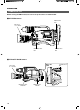
CONNECTION EXAMPLE OF RM-P210 (CONNECTION OF 2 UNITS) Standard connection of RM-P210 (Connection of 2 units) Intercom headset KA-310 OPERATE/WARNING LIGHT RESET FILTER ALARM 1 3200k 2 5600k+1/8ND 3 5600k+1/64ND SHUTTER STATUS RM VTR COUNTER CTL TC UB CH-1 CH-2 CH-1 FRONT REAR AUDIO INPUT OFF CALL LOLUX STRETCH NORMAL COMPRESS BACK L NORMAL SPOT L Camera cable VC-P110 CH-2 AUTO MANUAL AUDIO SELECT LEVEL BLACK LEVEL ON CH-1 AUDIO CH-2 FULL AUTO INCOM MIC CARBON DYNAMIC INCOM MIC
CONNECTION CAMERA SETUP Before turning the RM-P210 on, be sure to set up the camera as shown below.
CONNECTION TURNING THE POWER ON REMOTE CONTROL UNIT RM-P210 PAINT WHITE MASTER BLACK AUTO 1. Connect the camera to the RM-P210 using a proper connection method. 2. Set the camera switches as shown on the previous page. 3. Press the POWER switch of the RM-P210 to ON. POWER IRIS W.BAL P B MID I A R B PRESET AUTO MANU O CLOSE OPEN POWER switch NOTE ● When an item is controllable from both the RM-210 and the camera, the control from the camera is defeated.
PREPARATIONS AND MAIN FUNCTIONS CAMERA CABLE LENGTH SETUP Cable length setup is required when a camera is connected to the RM-P210 for the first time or when the camera cable length is changed. The cable length setup value is stored in the memory inside the RM-P210 and is held even after it is turned OFF. FULL AUTO F1 F3 MENU/SHUTTER GAIN SHUTTER P 1. Press and hold the MENU button for about 1 second until the LCD display shows the menu display.
PREPARATIONS AND MAIN FUNCTIONS ADJUSTMENTS FOR GENLOCK OPERATION Genlocking is required for a system, which uses an SEG (special effects generator) as the main signal source. REF. : “Example of RM-P210 (Connection 2 units) ” on page 9. NOTE ● The following adjustments can be made more accurately when using a vectorscope and waveform monitor. ● Be sure to use an underscanned video monitor. ● It is not permitted to genlock the system components using a VCR playback signal.
PREPARATIONS AND MAIN FUNCTIONS INTERCOM Intercommunications between operators are necessary in a system composed of multiple cameras and remote control units. Rear panel TALLY PGM PVW INTERCOM C H C AUX VIDEO INPUT G G RTS Front panel INTERCOM LEVEL control TALLY CALL FULL AUTO F1 SHUTTER 2. CABLE BARS F2 GAIN INTERCOM LEVEL The intercom employs the RTS system. If it is required to change this to a 2-wire system, consult your nearest JVC-authorized service agent.
PREPARATIONS AND MAIN FUNCTIONS FUNCTION KEYS Up to four of the functions listed at the bottom of this page can be assigned to function keys F1 to F4 so that each function can be switched on or off by pressing the corresponding key. (For the assignment of functions: REF. Items 5H to 5K, “FUNC1” to “FUNC4” in the OPERATION MENU description on page 25.) In the example shown on the left, the functions are assigned as shown in the following table.
CAMERA ADJUSTMENTS SHUTTER SPEED ADJUSTMENT Turning the SHUTTER control can vary the shutter speed of the camera. The LCD display shows the shutter speed during the adjustment operation. 1. Press the SHUTTER control to activate the shutter speed variation facility, which is indicated by the lighting of the SHUTTER lamp. 2. Turn the SHUTTER control to vary the shutter speed. The LCD display shows the shutter speed during the adjustment operation.
CAMERA ADJUSTMENTS IRIS ADJUSTMENT The camera lens iris can be adjusted from the RM-P210. W T Iris MODE switch 1. When the lamp in the IRIS AUTO/MANU button is not lit, the iris control is set to AUTO mode, in which the iris level is controlled automatically according to the light intensity. The auto iris value cannot be adjusted with the IRIS control. 2.
CAMERA ADJUSTMENTS WHITE BALANCE ADJUSTMENT Since color temperature varies depending on the light source, the white balance should be adjusted whenever the main light source illuminating the object being shot changes. AUTO white balance adjustment (AUTO SETUP) AUTO WHITE button 1. 2. REMOTE CONTROL UNIT RM-P210 U/SHUTTER GAIN PAINT WHITE HIGH VARIABLE PUSH-ON PUSH-ON POWER IRIS W.
MENU OPERATION FLOW OF MENUS The menus displayed on the RM-210 are provided in the form shown below. The displayed items and values are variable depending on the connected camera model. (The items and values that are not available with the camera are not displayed.
MENU OPERATION MENU SETUP METHOD Each menu is displayed on the LCD display and can be set up using the MENU button and the control knob. The values set in the "4: PROCESS" and "5: OPERATION" menus can be saved in files A and B. FULL AUTO F1 F3 MENU/SHUTTER GAIN SHUTTER P STEP HIGH BARS F2 STR OFF ALC CMP 0dB LUX F4 MENU SHUTTER VARIABLE PUSH-ON PUSH-ON 1.
MENU OPERATION GENLOCK MENU This menu is used to set the camera cable length to the length actually used. ( REF. : “Adjustments for Genlock Operation” on page 13.) No. Item Function, Operation Available Settings 1A H PHASE Adjustment of the Horizontal sync phase of genlocking. 0 to 255 1B SC COARSE Coarse adjustment of the color phase of genlocking. Use a vectorscope, etc.
MENU OPERATION FILE MENU The values set with the menu and applied to the RM-P210 can be saved in two files named A and B. FULL AUTO F1 F3 MENU/SHUTTER GAIN SHUTTER P 1. Press and hold the MENU button for 3 seconds until the LCD display shows the menu display. The cursor ( ) indicates that the item being pointed to can be varied. 2. Turn the control knob to move the cursor ( ) to “3: FILE”. 3. Press the control knob to move the cursor ( ) below to “3A: READ FILE”. STEP HIGH 3.
MENU OPERATION PROCESS MENU This menu sets the functions built into the camera. (Some of the following items cannot be set if a local remote control unit is connected to the camera or depending on the connected camera model.) No. Item Function, Operation Available Settings Initial Setting OFF ON ON 4A DETAIL ON/OFF setting of the detail enhancement function. OFF : Detail enhancement is deactivated. ON : Detail enhancement is activated. 4B DETAIL LEVEL Adjusts the detail enhancement level.
MENU OPERATION PROCESS MENU (CONTINUED) No. Item Function, Operation Available Settings Initial Setting 4I V.RESOLUTION Increases the vertical resolution. NORMAL : Standard value. V.MAX : Increased value. NOTE When the vertical resolution is increased, the sensitivity deteriorates and bright areas of objects may appear to be colored. NORMAL V.MAX NORMAL 4J GAMMA ON/OFF setting of the gamma curve correction, which determines the reproduction of black. OFF : Gamma correction is deactivated.
MENU OPERATION OPERATION MENU This menu sets the functions built into the RM-P210. No. Item Function, Operation Available Settings 5A Initial Setting SHUTTER Selects whether the front panel SHUTTER control varies the shutter speed in steps or in fine variation. STEP : Shutter speed variation in steps. VARIABLE: Fine, continual variation to be used when shooting a computer monitor, etc. STEP VARIABLE STEP 5B V.
MENU OPERATION LCD MODE MENU This menu sets up the LCD display. No. Item Function, Operation 6A CONTRAST Adjusts the contrast of the LCD display. 6B BACKLIGHT Adjusts the setting of the backlight of the LCD display. OFF : Backlight is turned off. ON : Backlight is turned on. 6Z BACK Returns to the previous display.
MENU OPERATION SYSTEM RESET MENU This menu resets the values set by the user to the initial values. FULL AUTO F1 F3 MENU/SHUTTER GAIN SHUTTER P STEP HIGH BARS F2 STR 1/1000 ALC CMP +9dB LUX F4 MENU SHUTTER VARIABLE PUSH-ON PUSH-ON MID LOW R GAIN M DOWN UP DOWN UP Control knob LCD display 1. MENU button 6: LCD MODE 1. Press and hold the MENU button (approx. 1 second) until the LCD display shows the menu display.
GENERAL WARNING MESSAGES To prevent operational errors, the LCD display shows one of the following warning messages when an erroneous operation is performed. Displayed Message Cause Check Point INVALID ENTRY GAIN : LOLUX The gain is set to the LoLux mode. Exit from the LoLux mode, and then adjust the gain again. INVALID ENTRY FULL AUTO : ON The FULL AUTO button is ON. Press the FULL AUTO button so that the lamp in it turns off, then retry operation. INVALID ENTRY GAIN : ALC + EEI ACC+EEI is ON.
GENERAL FUNCTIONS AVAILABLE DEPENDING ON CAMERA MODELS Connected Model Function IRIS AUTO IRIS AI LEVEL MANUAL IRIS IRIS LEVEL MASTER BLACK WHITE PRESET MANUAL BALANCE GAIN LOLUX SHUTTER KY- DETAIL LEVEL DETAIL V/H BAL DETAIL FREQUENCY LOW MIDDLE HIGH D29 KY- SKIN DETAIL OFF ON OFF
GENERAL TROUBLESHOOTING Symptom Colors in the monitor screen are abnormal. (During genlocking) Video troubles Synchronization is not possible. Check Points Page • Is the SC phase adjusted properly? P. 13 • Are the BB or VBS signals applied to the GENLOCK INPUT P. 13 connectors? • Is the VCR playback signal supplied directly without passing through a TBC? Pressing the corresponding • Functions that are not available on the camera cannot be button cannot start the controlled. operation.
GENERAL SPECIFICATIONS Output Signals Composite video signal: 1 V(p-p), 75 W, 2 output R/G/B signals : 0.7 V(p-p), 75 W, x 1 each (without sync) Y/R-Y/B-Y signals : Y: 1 V(p-p), 75 W (including sync) R-Y: 0.7 V(p-p), 75 W, B-Y: 0.7 V(p-p), 75 W, (75% color bar) Input Signals GENLOCK signal : VBS, 1 V(p-p), or BB, 0.
RM-P210 REMOTE CONTROL UNIT is a registered trademark owned by Victor Company of Japan, Limited. is a registered trademark in Japan, the U.S.A., the U.K. and many other countries. © 2005 Victor Company of Japan, Limited.