R INTRODUCTION BASIC OPERATIONS APPLIED OPERATIONS REMOTE CONTROL UNIT RM-P2580 CONNECTIONS INSTRUCTIONS MENU SCREEN SETUPS OTHER For Customer Use: Enter below the Model No. and Serial No. which is located on the body. Retain this information for future reference. Model No. RM-P2580 Serial No.
SAFETY PRECAUTIONS CAUTION RISK OF ELECTRIC SHOCK DO NOT OPEN TO REDUCE THE RISK OF ELECTRIC SHOCK, DO NOT REMOVE COVER (OR BACK). NO USER SERVICEABLE PARTS INSIDE. REFER SERVICING TO QUALIFIED SERVICE PERSONNEL. Information for USA This device complies with Part 15 of the FCC Rules. Changes or modifications not approved by JVC could void the user's authority to operate the equipment.
1. INTRODUCTION Thank you for purchasing the JVC RM-P2580. These instructions are for the RM-P2580U. CONTENTS 1. INTRODUCTION ● CONTENTS .......................................................................................................................................... 3 ● FEATURES ........................................................................................................................................... 4 ● ACCESSORIES ..................................................................
1. INTRODUCTION FEATURES 䢇 Presetting of up to 64 positions (including the home positions) each, for up to 8 combination cameras (TK-C675B). 䢇 Built-in PAN, TILT and ZOOM control for up to 8 cameras. 䢇 RS-485 connection system enables cascaded connection of cameras. 䢇 Built-in sequential switcher. 䢇 Alarm input terminals. 䢇 Data I/O terminals for interlocked operation with external peripherals.
1.
1.
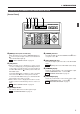
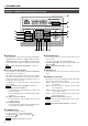
1. INTRODUCTION CONTROLS, CONNECTORS AND INDICATORS (Continued) $ [AUTO PATROL] button ⁄ [FOCUS NEAR, FAR] FOCUS control buttons Press this button to switch the camera positions automatically in a preset order and at preset time intervals. POSITION The POSITION display becomes as shown on the left during AUTO PATROL. The AUTO PATROL function can be set on a per-camera basis. REF. : “AUTO PATROL OPERATION” on page 15.
1.
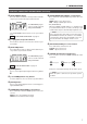
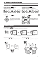
2. BASIC OPERATIONS Manual Operation Camera Selection Position Selection ( REF. :Page 10) Switching to the selected camera video. 1 CAMERA 8 Pan/Tilt Operation ( REF. ( REF. : Page 11) Switching the camera to the selected video position. ENTER : Page 12) 1 POSITION Lens Operation 0 ENTER /HOME ( REF. : Page 12) PAN/TILT CLOSE (TILT) Tilts the camera up and down, (PAN) Pans the camera in the left and right directions.
2. BASIC OPERATIONS CAMERA SELECTION Selecting a Desired Camera CAMERA display 1. 2. Press the CAMERA button so that the indicator lights up. 3. Press the ENTER button to enter the input camera number. The video of the selected camera will be output from the MONITOR OUTPUT connectors on the rear panel. At this time, the period in the CAMERA display disappears and the POSITION display shows the camera operation details (position, fixed camera, AUTO PATROL, AUTO PAN, etc.).
2. BASIC OPERATIONS POSITION SELECTION Selecting a Desired Preset Position ( REF. : Page 27 for the position presetting.) 1. 2. CAMERA display POSITION display REMOTE CONTROL UNIT RM-P2580 CAMERA POSITION POWER PO WER ALARM AUTO F-1 F-2 Press the POSITION button so that the indicator lights up. Input the position number using the numeric keys (0 to 9). The input figure is shown in the POSITION display together with a period after it.
2. BASIC OPERATIONS MANUAL OPERATION The manual operation allows you to PAN or TILT the selected camera and to control its lens. NOTES ● Manual operation is not available in the AUTO SEQUENCE or AUTO PATROL modes. ● Only the lever tilting operation is available in the AUTO PAN mode.
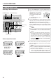
2. BASIC OPERATIONS AUTO SEQUENCE OPERATION Operation with the Basic System ( REF. : Page 32 for the switching interval setting.) When the AUTO button is pressed, the AUTO indicator lights up and the MONITOR OUTPUT connectors output the camera images, switching them in order of camera numbers at constant intervals. (Example) When using cameras 1 to 6 Camera 1 Camera 2 Camera 3 Camera 6 Camera 5 Camera 4 1. Lights up.
2. BASIC OPERATIONS AUTO PAN OPERATION The AUTO PAN operation consists of low-speed horizontal movement of a camera between preset positions at a constant time interval. Automatic panning is set between 2 points. This function can be set on individual cameras. SET button 1. POSITION display REMOTE CONTROL UNIT RM-P2580 CAMERA SETUP MENU NOTE During the AUTO PAN operation, the PAN/TILT control lever can be operated only in the TILT direction ( ).
2. BASIC OPERATIONS AUTO PATROL OPERATION The AUTO PATROL operation consists of high-speed camera movement between multiple pre-set positions, in a sequence and at time intervals set by the user. This function can be set on individual cameras. POSITION display 1. Press the AUTO PATROL button. The LED indicator lights up and the AUTO PATROL operation starts. The POSITION display shows “AP” at this time. NOTE During the AUTO PATROL operation, the manual operation is not available. 2.
2. BASIC OPERATIONS KEY LOCK (PREVENTION OF OPERATION MISTAKE) The KEY LOCK function helps prevent operational mistakes by inhibiting the functions of all the buttons and the joystick on the control panel. KEY LOCK SET button indicator 1. Press and hold the SET button for more than 3 seconds to put the unit into KEY LOCK status. The KEY LOCK indicator lights up, and all the buttons and the joystick on the control panel become inactive. 2.
3. APPLIED OPERATIONS ALARM OPERATION Alarm input signals can be applied to the DATA I/O terminals on the rear panel. The unit functions in either the ALARM PRIORITY mode or the MANUAL PRIORITY mode when an alarm signal is input. ( REF. : “CONTROL UNIT SCREEN” on page 28 and “PRIORITY item of ALARM SCREEN” on page 32.
4. CONNECTIONS A MODE ● ● ● ● ● ● The master monitor displays the video signal from the selected camera. Use the CAMERA SW input to switch the video signal and record it on the VCR. The preset operation, manual operation, AUTO PAN operation and AUTO PATROL operation are available for each camera. When fixed cameras are used, only the video signal can be switched. The alarm operation is available using the DATA I/O terminals.
4. CONNECTIONS APPLIED SYSTEM (B MODE) This system accepts the connection of up to 16 cameras. The video is recorded by means of a frame switcher. Setting Procedure When an alarm input is required to the SW-D7000/ SW-D8000, be sure to use the ALM OUTPUT of the I/O terminal of RM-P2580. ● Read the "Instruction Manual" for each piece of equipment to be connected before performing the connection.
4. CONNECTIONS B MODE ● ● ● ● ● ● The monitor displays the video that is switched by the frame switcher. The master monitor displays either a multi-split screen or the menu screen. The cameras are selected by controlling the frame switcher through the SERIAL-2 connector. The preset operation, manual operation, AUTO PAN operation and AUTO PATROL operation are individually available for each camera. Alarm operation with up to 16 alarm inputs is available by using the DATA I/O terminals.
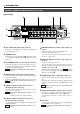
4. CONNECTIONS REAR PANEL CONNECTORS TO CAMERA Connection to control the camera. (The RM-P2580 is compatible with a TK-C675B camera.) Communication is carried out by MULTIDROP FULL DUPLEX (RS-485, FULL DUPLEX). RM-P2580 RX+ RX- TX+ TX- R R T T X X X X + – + – CAMERA 1 A B C D A T X B T X C R X D R X Hold. + – + – CAMERA 2 A T X B T X C R X D R X Attach or remove each cable by pushing down and holding each terminal connector, as shown above.
4. CONNECTIONS REAR PANEL CONNECTORS (Continued) DATA I/O REF. : “DATA I/O SCREEN” on page 30 for the input/output signal switching. COM 1 2 3 4 5 6 7 8 DATA I / O UNIT CAMERA COM 9/1 10/2 11/3 12/4 13/5 14/6 15/7 16/8 COM AUTO ALARM COM SW COM HOLD 䡵 ALARM INPUTS 1 to 16 TTL level (Make/Break), input duration 70 ms or more. REF. : “CONTROL UNIT SCREEN” on page 28 and “POLARITY item of DATA I/O SCREEN (INPUT ASSIGNMENT SCREEN)” on page 31 for the Make/ Break switching.
5. MENU SCREEN SETUPS FLOW OF MENUS For details of each screen, please refer to the reference pages 26 to 28. SET UP screen POSITION SETUP POSITION SETUP screen ( REF. : Page 27) CAMERA CAMERA screen ( REF. : Page 28) CONTROL UNIT screen ( REF. : Page 28) OPTION screen ( REF. : Page 29) MAX CAMERA (Displayed at B Mode only) P/T SPEED SERIAL-2 (Displayed at B Mode only) CAMERA SELECTION (Displayed at A Mode only) CAMERA SELECTION screen ( REF. : Page 29) FACTORY SETTING FACTORY SETTING screen ( REF.
5. MENU SCREEN SETUPS MENU OPERATION SET button PAN/TILT control lever MENU button 1. 2. Set the POWER switch on the rear panel to “ON”. 3. Select a menu item by moving the cursor (>) using the PAN/TILT control lever. • Tilt the lever upwards (8) to move the cursor upwards. • Tilt the lever downwards (9) to move the cursor downwards. 4. Press the SET button to display the sub-menu of the menu item selected.
5. MENU SCREEN SETUPS POSITION SETUP SCREEN This screen is used to preset, correct or delete the camera positions. No position can be selected unless it has been preset. Up to 64 positions including the home position can be preset. Presetting and Correcting Camera Positions MENU button CAMERA button SET button POSITION button REMOTE CONTROL UNIT RM-P2580 CAMERA SETUP MENU POSITION POWER ALARM SET AUTO F-1 F-2 1. Press and hold the MENU button for about 3 seconds to display the SETUP screen.
5. MENU SCREEN SETUPS CAMERA SCREEN To set up the connected cameras, please refer to the instruction manuals of the individual cameras. Use the following procedure to display the menu. 1. Press and hold the MENU button for about 3 seconds to display the SETUP screen. 2. Select CAMERA and press the SET button. The menu screen for the connected cameras is displayed. CONTROL UNIT SCREEN This screen is used to set the functions of the remote control unit. 1.
5. MENU SCREEN SETUPS OPTION SCREEN Default Options Item MAX CAMERA (Displayed at B Mode only) 1, 2,...
5. MENU SCREEN SETUPS ALARM SCREEN Item Function Options Default ALARM Sets whether an alarm input is accepted during manual operation. ALARM : Alarm input is accepted even during manual operation. MANUAL : Alarm input is not accepted during manual operation. ALARM, MANUAL ALARM TIME Sets how long the alarm operation will continue after an alarm input. 5, 6, 7, 8, 9, 10, 15, 20, 25, 30, 60, SERIES 15 SEC BUZZER TIME Sets the buzzer sound generated upon an alarm input.
6. OTHER TROUBLESHOOTING Symptom Ref. Page Check Video is not displayed. • Is the power supply connected properly to all off the cameras? • Are the cameras connected properly to the VIDEO INPUT connectors? Pages 21, 22 The cameras cannot be initialized. • Are the camera heads compatible with this unit? — The cameras point in arbitrary directions after initialization. • Preset their home positions. Page 27 None of the remote control function operate.
6. OTHER SPECIFICATIONS Applicable cameras Video lines : TK-C675B Max. number of connected cameras : 8 (A mode), 16(B mode) Number of inputs : 8 (BNC) Max. cable length : 1.2 km Level : Composite, 1 V(p-p) Control terminals : Push terminals (RS-485) 9600 bps. Number of outputs : 2 (BNC) Max. number of DATA I/O terminals : 16 Other Max. number of alarm inputs/outputs : 16 Supply voltage : AC100–120V Number of UNIT ALARM outputs : 1 line (open-collector) Power consumption : Approx.
RM-P2580 REMOTE CONTROL UNIT R is a registered trademark owned by VICTOR COMPANY OF JAPAN, LTD. is a registered trademark in Japan, the U.S.A., the U.K. and many other countries.