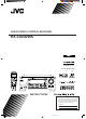
AUDIO/ VIDEO CONTROL RECEIVER RX-1024VBK TV/CATV/ DBS VCR 1 POWER POWER DVD VCR 1 VCR 2 VIDEO PHONO TV/DBS AUDIO POWER CD TAPE/MD AM FM SURROUND CNTR TONE – 1 3 – REAR · L + 4 5 INPUT 7/P 8 – SEA MODE DISC – MENU 6 ENTER MASTER VOLUME – REAR · R + EFFECT SOUND + CNTR 2 TEST MODE DIGITAL/ ANALOG SLEEP 0 FM MODE/ MUTE D I G I T A L + SUBWOOFER 10 RETURN – +10 + 100+ AUDIO/ TV/VCR + CHANNEL RX-1024V AUDIO/VIDEO CONTROL RECEIVER 9 STANDBY DOLBY SURROUND C
Warnings, Cautions and Others CAUTION RISK OF ELECTRIC SHOCK DO NOT OPEN CAUTION To reduce the risk of electrical shocks, fire, etc.: 1. Do not remove screws, covers or cabinet. 2. Do not expose this appliance to rain or moisture. CAUTION: TO REDUCE THE RISK OF ELECTRIC SHOCK. DO NOT REMOVE COVER (OR BACK) NO USER SERVICEABLE PARTS INSIDE. REFER SERVICING TO QUALIFIED SERVICE PERSONNEL.
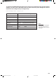
To get the best DSP (Digital Signal Processor) effect in your listening room, note the speaker settings you have set on the table below for future reference (even though the receiver memorizes the settings until you change them). For actual setting procedures, see pages 19 to 21.
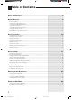
Table of Contents Parts Identification ...................................................................................... 3 Getting Started........................................................................................... 4 Before Installation ................................................................................................................................................................... 4 Checking the Supplied Accessories ......................................................
Using the DSP Modes ................................................................................ 28 Using the 3D-PHONIC Modes ............................................................................................................................................. 29 Using the DAP Modes .......................................................................................................................................................... 32 Using the Dolby Digital and Dolby Pro Logic Modes .........
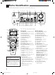
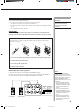
Parts Identification Become familiar with the buttons and controls on the receiver before use.
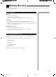
Getting Started This section explains how to connect audio/video components and speakers to the receiver, and how to connect the power supply. Before Installation General • • • Be sure your hands are dry. Turn the power off to all components. Read the manuals supplied with the components you are going to connect. Locations • • • Install the receiver in a location that is level and protected from moisture. The temperature around the receiver must be between 23˚ and 95˚ F (–5˚ and 35˚ C).
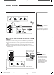
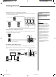
Getting Started Connecting the FM and AM Antennas FM Antenna Connections 1 2 4 3 FM Antenna ANTENNA Extend the FM wire antenna horizontally. FM Note: 4 FM 75 If reception is poor, connect the outside antenna. Before attaching a 75Ω coaxial cable (the kind with a round wire going to an outside antenna), disconnect the supplied FM wire antenna. Outside FM Antenna Wire GND 1 GND 2 3 7/16 in. AM LOOP AM EXT 13/16 in.
Connecting the Speakers You can connect the following speakers: • Two pairs of front speakers to produce normal stereo sound. • One pair of rear speakers to enjoy the surround effect. • One center speaker to produce more effective surround effect (to emphasize human voices). • One subwoofer to enhance the bass. CAUTION: Use speakers with the SPEAKER IMPEDANCE indicated by the speaker terminals.
Getting Started Connecting the rear and center speakers Connect the rear speakers to the REAR SPEAKERS terminals and a center speaker to the CENTER SPEAKER terminals. Center speaker RIGHT LEFT CAUTION: Use speakers with the SPEAKER IMPEDANCE indicated by the speaker terminals.
Connecting Audio/Video Components You can connect the following audio/video components to this receiver. Refer also to the manuals supplied with your components. If you want to connect a component not listed in the table below, refer to the manual supplied with it.
Getting Started Video component connections Use the cables with RCA pin plugs (not supplied). Connect the white plug to the audio left jack, the red plug to the audio right jack, and the yellow plug to the video jack. If your video components have S-video (Y/C-separation) terminals, connect them using S-video cables (not supplied). Connecting these video components through the S-video input/output terminals will give you better picture playback (or recording) quality.
Connecting DVD player Note: VIDEO RIGHT AUDIO DVD player RIGHT LEFT VIDEO S-VIDEO DVD DVD To audio/video output TV SOUND /DBS To enjoy Dolby Digital with the DVD player as the source, connect the DVD player, using the method described in “Digital connections” on page 11.
Getting Started Digital connections This receiver is equipped with three DIGITAL IN terminals — one digital coaxial terminal and two digital optical terminals. To enjoy Dolby Digital, you have to connect the source components using the DIGITAL IN terminals. You can connect any component to any one of the digital terminals using the digital coaxial cable (not supplied) or digital optical cable (not supplied).
Connecting the Power Cord Notes: Before plugging the receiver into an AC outlet, make sure that all connections have been made. When the power cord is connected, the STANDBY lamp above the POWER button lights up. Keep the power cord away from the connecting cables and antenna. The power cord may cause noise or screen interference. We recommend that you use a coaxial cable to connect the antenna, since it is well-shielded against interference.
Basic Operations The following operations are commonly used when you play any sound source. IMPORTANT: When using the Remote Control, check to see if its remote control mode selector is set to the correct position: To operate an audio system, TV, and VCR, set it to “AUDIO/TV/ VCR.” To operate a CATV converter, set it to “CATV.” To operate a DBS tuner, set it to “DBS.
From the remote control: Press one of the source selecting buttons directly. DVD VCR1 DVD VCR 1 VCR 2 VIDEO CD TAPE/MD PHONO TV/DBS Selects the DVD player. Selects the video component connected to the VCR1 jacks. VCR2 Selects the video component connected to the VCR2 jacks. VIDEO Selects the video component connected to the VIDEO jacks. CD* Selects the CD player. TAPE/MD* Selects the cassette deck or the MD recorder. PHONO* Selects the turntable. FM* Selects an FM broadcast.
Basic Operations Selecting the Front Speakers Note: On the front panel only: SPEAKERS 1 2 When you have connected two pairs of the front speakers, you can select which to use. Press SPEAKERS 1 or SPEAKERS 2 to select the speaker to use. Each time you press the button, the lamp on the respective button turns on and off. When the lamp on either button lights up, the respective speakers are activated.
Attenuating the Input Signal When the input level of the playing source through the analog terminals is too high, the sounds will be distorted. If this happens, you need to attenuate the input signal level to prevent the sound distortion. On the front panel only: Press and hold SOUND SELECT/INPUT ATT until “INPUT ATT ON” appears on the display. The ATT indicator also lights up on the display. SOUND SELECT Notes: • This function is available only for the sources connected using the analog terminals.
Basic Settings Some of the following settings are required after connecting and positioning your speakers in your listening room, while others will make operations easier. AUDIO/ TV/VCR CATV DBS IMPORTANT: When using the Remote Control, check to see if its remote control mode selector is set to the correct position: To operate this receiver, set it to “AUDIO/TV/VCR” (except when selecting the DBS tuner as the source).
Adjusting the Front Speaker Output Balance If the sounds you hear from the front right and left speakers are unequal, you can adjust the speaker output balance. On the front panel only: BALANCE/SURROUND ADJUST 1. Press BALANCE/SURROUND ADJUST repeatedly until “L/R BALANCE” appears on the display. The display changes to show the current setting. MULTI JOG 2. Turn MULTI JOG to adjust the balance, while the indication of the previous step is still on the display.
Basic Settings Digital Input (DIGITAL IN) Terminal Setting When you use the digital input terminals, you have to register what components are connected to which terminals (DIGITAL IN 1/2/3). On the front panel only: 1. Press SETTING repeatedly until “DIGITAL IN” appears on the display. The display changes to show the current setting. SETTING DIGITAL 2 terminal setting Note: When shipped from the factory, the DIGITAL IN terminals can be used as the digital input for the following components.
Center Delay Time Setting Register the delay time of the sound from the center speaker, comparing that of the sound from the front speakers. If the distance from your listening point to the center speaker is equal to that to the front speakers, select 0 msec. As the distance to the center speaker becomes shorter, increase the delay time. On the front panel only: 1. Press SETTING repeatedly until “CENTER DELAY” appears on the display. The display changes to show the current setting. 2.
Basic Settings 2. Turn MULTI JOG to select the crossover frequency level according to the size of the small speaker connected, while the indication of the previous step is still on the display. As you turn it, the display changes to show the following: CROSS: 80Hz CROSS: 80Hz CROSS:100Hz CROSS:120Hz CROSS:100Hz CROSS:120Hz Select this when the cone speaker unit built in the speaker is about 4 3/4 inches (12 cm). Select this when the cone speaker unit built in the speaker is about 3 15/16 inches (10 cm).
One Touch Operation This receiver can memorize the optimum sound settings for each playing source. About the One Touch Operation JVC’s One Touch Operation function is used to assign and store different sound settings for each different playing source. By using this function, you do not have to change the settings every time you change the source. The stored settings for the newly selected source are automatically recalled. Note: If the source is FM or AM, you can assign a different setting for each band.
Receiving Radio Broadcasts You can browse through all the stations or use the preset function to go immediately to a particular station. AUDIO/ TV/VCR CATV DBS IMPORTANT: When using the Remote Control, check to see if its remote control mode selector is set to the correct position: To operate this receiver, set it to “AUDIO/TV/VCR” (except when selecting the DBS tuner as the source). Tuning in Stations Manually On the front panel: 1. Press FM/AM TUNING to select the band.
5. Repeat steps 1 to 4 until you store all the stations you want. To erase a stored preset station Storing a new station on a used number erases the previously stored one. To tune in a preset station On the front panel: TUNER PRESET 1. Press TUNER PRESET. MULTI JOG 2. Turn MULTI JOG to select a preset channel. From the remote control: 1. Press FM or AM. AM 2. Press 10 keys to select a preset channel number. • For channel number 5, press 5. • For channel number 15, press +10 then 5.
Receiving Radio Broadcasts Assigning Names to Preset Stations You can assign a name of up to four characters to each preset station. When a preset station is tuned in, its assigned name will appear on the display. On the front panel only: 1. Tune in a preset station. See page 24 for details. 2. Press TUNER/SEA MEMORY. The preset channel number starts flashing for about 5 seconds. TUNER/SEA MEMORY If you turn MULTI JOG while the preset channel number is flashing, you can change the preset channel number.
Using the SEA Modes The SEA (Sound Effect Amplifier) modes give you control of the way your music sounds. IMPORTANT: When using the Remote Control, check to see if its remote control mode selector is set to the correct position: To operate this receiver, set it to “AUDIO/TV/VCR” (except when selecting the DBS tuner as the source). AUDIO/ TV/VCR CATV DBS Selecting Your Favorite SEA Mode Notes: On the front panel: • The SEA modes cannot be used for recording.
Using the SEA Modes Creating Your Own SEA Mode You can adjust and store your own SEA adjustment into memory (SEA USERMODE). On the front panel only: If you do not want to store your adjustment, but rather want to adjust the SEA temporarily, skip step 4 below. 1. Press SEA ADJUST repeatedly until the frequency range (100Hz, 1kHz or 10kHz) you want appears on the display. SEA SEA ADJUST FR VOLUME 100 1k SEA FR 10k VOLUME 100 1k 10k 2.
Using the DSP Modes The built-in Surround Processor provides three types of the DSP (Digital Signal Processor) mode — 3DPHONIC mode, DAP (Digital Acoustic Processor) mode and Surround mode (Dolby Digital, Dolby Pro Logic and JVC’s Theater Surround.) On the 3D-PHONIC mode The 3D-PHONIC mode gives you such a nearly surround effect as it is reproduced through the Dolby Surround decoder, which is widely used to reproduce sounds with a feeling of movement like those experienced in movie theaters.
Using the DSP Modes IMPORTANT: When using the Remote Control, check to see if its remote control mode selector is set to the correct position: To operate this receiver, set it to “AUDIO/TV/VCR” (except when selecting the DBS tuner as the source). AUDIO/ TV/VCR CATV DBS Using the 3D-PHONIC Modes When using the 3D-PHONIC modes, you need only two front speakers to reproduce the soundtracks of software encoded with Dolby Digital (bearing the mark ) or DOLBY SURROUND ).
4. Press BALANCE/SURROUND ADJUST repeatedly until “DSP EFFECT” appears on the display. The display changes to show the current setting. 5. Turn MULTI JOG to select the effect level, while the indication of the previous step is still on the display. As you turn it, the effect level changes as follows: DSP EFFECT 1 DSP EFFECT 2 DSP EFFECT 5 BALANCE/SURROUND ADJUST Note: Once you have adjusted the 3DPHONIC modes, it is memorized for each 3D-PHONIC mode.
Using the DSP Modes From the remote control: 1. Select and play the source encoded with Dolby Digital (bearing the mark DOLBY SURROUND ). ) or with Dolby Surround (bearing the mark • When you play back the source encoded with Dolby Digital and select the digital input for that source, the Ÿ DIGITAL indicator lights up on the display. D I G I T A L 2. Press SURROUND MODE repeatedly until the mode — 3D ACTION (or 3D DIGITAL), 3D DRAMA, or 3D THEATER — you want appears on the display.
Using the DAP Modes You can use five DAP modes — “Live Club, Dance Club, Hall, Pavilion, and Headphones” for any source. Among the DAP modes, “Headphones” is very special. It can create the same stereo sound as you listen through the speakers off air while listening to a source using headphones. So, you can feel as if you were not using the headphones and listening to music in a room. If the digital input is selected to play the source encoded with Dolby Digital, you can only select “Headphones.
Using the DSP Modes 4. Adjust the effect level. 1) Press BALANCE/SURROUND ADJUST repeatedly until “DSP EFFECT” appears on the display. 2) Turn MULTI JOG to select the effect level, while the indication of the previous step is still on the display. As you turn it, the effect level changes as follows: DSP EFFECT 1 DSP EFFECT 2 DSP EFFECT 3 BALANCE/SURROUND ADJUST MULTI JOG DSP EFFECT 4 DSP EFFECT 5 Note: As the number increases, the selected DAP mode becomes stronger.
Using the Dolby Digital and Dolby Pro Logic Modes Notes: Once you have adjusted the Dolby Digital and Dolby Pro Logic modes, this receiver memorizes adjustment for each mode. To activate the Dolby Digital and Dolby Pro Logic modes, follow the procedure below. From the remote control: 1. Select and play the source encoded with Dolby Digital (bearing the mark DOLBY SURROUND ).
Using the DSP Modes 4. Press TEST to start checking the speaker output balance. “TEST TONE L” starts flashing on the display, and a test tone comes out of the speakers in the following order: L TEST TONE L TEST TONE C (Left front speaker) (Center speaker) C 4 Notes: • No test tone comes out of the center speakers when “CENTER SPK” is set to “NONE” (see page 19). • No test tone comes out of the rear speakers when “REAR SPK” is set to “NONE” (see page 19).
On the front panel: Notes: You can also use the buttons on the front panel to adjust the Dolby Digital and Dolby Pro Logic modes. However, no test tone is available when using the buttons on the front panel. So, make adjustments while listening to the sound of the source played back. • To enjoy the software encoded with Dolby Digital, you must connect the source component using the digital terminal on the rear of this receiver.
Using the DSP Modes Using the Theater Surround Mode Notes: Once you have adjusted the Theater Surround mode, this receiver memorizes the adjustment. To activate the Theater Surround mode, follow the procedure below. From the remote control: 1. Select and play the source encoded with Dolby Digital (bearing the mark DOLBY SURROUND ).
5. Adjust the speaker output levels as follows: • To adjust the center speaker level, press CNTR +/–. • To adjust the left rear speaker level, press REAR•L +/–. • To adjust the right rear speaker level, press REAR•R +/–. – CNTR 2 + 3 MENU Notes: – 5 – REAR · R + REAR · L + ENTER 8 6 9 TEST 6. Press TEST again to stop the test tone. 4 • You can adjust the speaker output levels and center tone without outputting the test tone.
Using the DSP Modes On the front panel: You can also use the buttons on the front panel to adjust the Theater Surround mode. However, no test tone is available when using the buttons on the front panel. So, make adjustments while listening to the sound of the source played back. 1. Select and play the source encoded with Dolby Digital (bearing the mark DOLBY SURROUND ).
5. Press BALANCE/SURROUND ADJUST repeatedly until “CENTER TONE” appears on the display. The display changes to show the current setting. BALANCE/SURROUND ADJUST 6. Turn MULTI JOG to select the center tone level you want, while the indication of the previous step is still on the display. The center tone adjustment affects the mid-frequency range, which the human voice is mostly made up of. As you turn it, the display changes to show the following: SOFT2 SOFT1 FLAT SHARP1 SHARP2 7.
Using the On-Screen Menus You can use the menus on the TV screen to control the receiver. To use this function, you need to connect the TV to the MONITOR OUT jack on the rear panel (see page 9), and set the TV’s input mode to the proper position to which the receiver is connected. Selecting the Source to Play (Also see page 13) Note 1. Press any button of ON SCREEN CONTROL % / fi / @ / # once. The MAIN MENU appears on the TV.
Adjusting the Front Speaker Output Balance (Also see page 18) 1. Press any button of ON SCREEN CONTROL % / fi / @ / # once. The MAIN MENU appears on the TV. MAIN MENU MAIN MENU 2. Press ON SCREEN CONTROL % / fi to move then press @ / #. The SOUND CONTROL menu appears on the TV. to “SOUND CONTROL,” 3. Press ON SCREEN CONTROL % / fi to move to “BAL.” (Balance). SOURCE :VCR1 VISUAL :VCR1 MODE :OFF ** ** ** SOUND CONTROL TUNER CONTROL SETTING ** ** ** :ENTER VOLUME : 20 SOUND CONTROL menu 4.
Using the On-Screen Menus Adjusting the Subwoofer Output Level (Also see page 16) MAIN MENU You can adjust the subwoofer output level if you have selected “YES” for the “SUBWOOFER” (see page 18). MAIN MENU SOURCE :ch 1 FM 87.5 MHz VISUAL :VCR1 MODE :OFF 1. Press any button of ON SCREEN CONTROL % / fi / @ / # once. The MAIN MENU appears on the TV. ** ** ** 2. Press ON SCREEN CONTROL % / fi to move then press @ / #. The SOUND CONTROL menu appears on the TV. to “SOUND CONTROL,” 3.
For Dolby Surround Pro Logic: “TEST TONE”: Output a test tone. “CENTER LEVEL”: Adjust the center speaker output level. ** “REAR L LEVEL”: Adjust the left rear speaker output level. * “REAR R LEVEL”: Adjust the right rear speaker output level. * “CENTER TONE”: Select the center tone level.
Using the On-Screen Menus Creating Your Own SEA Mode (Also see page 27) MAIN MENU 1. Press any button of ON SCREEN CONTROL % / fi / @ / # once. The MAIN MENU appears on the TV. 2. Press ON SCREEN CONTROL % / fi to move then press @ / #. The SOUND CONTROL menu appears. MAIN MENU to “SOUND CONTROL,” SOURCE :VCR1 VISUAL :VCR1 MODE :OFF ** ** ** SOUND CONTROL TUNER CONTROL SETTING ** ** ** :ENTER VOLUME : 20 3. Press ON SCREEN CONTROL % / fi to move The SEA menu appears. to “SEA,” then press @ / #.
4. Press ON SCREEN CONTROL @ / # to set (or adjust) the setting item selected in step 3. 5. When you finish, press EXIT repeatedly until the menu disappears from the TV. Operating the Tuner MAIN MENU 1. Press any button of ON SCREEN CONTROL % / fi / @ / # once. The MAIN MENU appears on the TV. 2. Press ON SCREEN CONTROL % / fi to move then press @ / #. The TUNER CONTROL menu appears. MAIN MENU to “TUNER CONTROL,” SOURCE :ch 1 FM 87.
Using the On-Screen Menus Assigning Names to the Preset Stations (Also see page 25) 1. Press any button of ON SCREEN CONTROL % / fi / @ / # once. The MAIN MENU appears on the TV. MAIN MENU MAIN MENU 2. Press ON SCREEN CONTROL % / fi to move then press @ / #. The TUNER CONTROL menu appears. to “TUNER CONTROL,” 3. Press ON SCREEN CONTROL % / fi to move to “PRESET CH.” SOURCE :ch 1 FM 87.
COMPU LINK Remote Control System The COMPU LINK remote control system allows you to operate JVC audio components through the remote sensor on the receiver. To use this remote control system, you need to connect JVC audio components through the COMPU LINK-3 (SYNCHRO) jacks (see below) in addition to the connections using cables with RCA pin plugs (see page 8) (and a digital cable if you want — see page 11). • Make sure that the AC power cords of these components are unplugged before connection.
TEXT COMPU LINK Remote Control System The TEXT COMPU LINK remote control system has been newly developed to deal with the disc information recorded in the CD Text* and MDs. Using these information in the discs, you can operate the CD player or MD recorder equipped with the TEXT COMPU LINK remote control system through the receiver. CONNECTIONS: * What is a CD Text? To use this remote control system, you need to connect the CD player and/or MD recorder you want to operate, following the procedures below.
OPERATIONS Notes: To use this remote control system, you need to connect the TV to the MONITOR OUT jack on the rear panel (see page 9), and set the TV’s input mode to the proper position to which the receiver is connected. Make sure you have connected the CD player or MD recorder equipped with the TEXT COMPU LINK remote control system. If not, you cannot use the following functions. Showing the Disc Information on the TV Screen 1. Press any button of ON SCREEN CONTROL % / fi / @ / # once.
TEXT COMPU LINK Remote Control System Searching a Disc (Only for the CD player) Search a disc by its performer: 1. Display the disc information screen by following the procedure on page 50. 2. Press ON SCREEN CONTROL % / fi to move press SET. The DISC SEARCH screen appears on the TV. to “SEARCH,” then 3. Press ON SCREEN CONTROL % / fi to move press SET. The PERFORMER SEARCH screen appears. to “PERFORMER”, then DISC SEARCH screen PERFORMER SEARCH screen 4.
5. Press SET again. Disc search starts, then the SEARCH RESULT screen, showing the disc titles, appears. SEARCH RESULT screen 6. On the SEARCH RESULT screen, you can do the following: • Changing the indication of the disc information: Press ON SCREEN CONTROL % / fi to move to a searched disc, then press @ / #. Each time you press @ / #, the disc information alternates between its disc title and its performer.
TEXT COMPU LINK Remote Control System Using the User File (Only for the CD Player with the User File Function) You can use the User File function through this receiver. For the User File function, refer to the manual supplied with your CD player. Using your own User Files: 1. Display the disc information screen by following the procedure on page 50. 2. Press ON SCREEN CONTROL % / fi to move press SET. The USER FILE screen appears on the TV.
Entering the Disc Information For the CD Player with the disc memory function: You can use the disc memory function through this receiver. The disc information (its performer, disc title, and its music genre) of normal audio CDs will be stored into the memory built in the CD player. For the disc memory function, refer to the manual supplied with your CD player. • The performer, disc title, and music genre information are usually recorded in a CD Text.
TEXT COMPU LINK Remote Control System 7. Press ON SCREEN CONTROL % / fi / @ / # to move FAVORITE (in this example),” then press SET. The TITLE INPUT: DISC 1 GENRE screen appears. 8. Press ON SCREEN CONTROL % / fi to move then press SET. The Disc Information screen appears again. to “DISC1: MY TITLE INPUT: DISC 1 GENRE screen to the genre you want, To show the unseen genres, press ON SCREEN CONTROL % / fi until they appear.
AV COMPU LINK Remote Control System The AV COMPU LINK remote control system allows you to operate JVC video components (TV, VCR, and DVD player) through the receiver. CONNECTIONS: To use this remote control system, you need to connect the video components you want to operate, following the procedures below. 1. If you have already plugged your VCR1 (the VCR connected to the VCR 1 jacks), DVD player, TV, and this receiver into the AC outlets, unplug their AC power cords first.
FUNCTIONS: Note: This remote control system allows you to use five functions listed below. Remote Control of DVD Player, VCR, and TV Using This Remote Control For the DVD player and the VCR: • Aim the remote control directly at the remote sensor on the each component. For the TV having AV COMPU LINK terminal “RECEIVER/AMP”: • Aim the remote control directly at the remote sensor on the receiver when operating the TV.
Operating JVC’s Audio/Video Components You can operate JVC’s audio and video components with this receiver’s remote control, since control signals for JVC components are preset in the remote control. IMPORTANT: To operate JVC’s audio components using this remote control: • You need to connect JVC audio components through the COMPU LINK-3 (SYNCHRO) jacks (see page 48) in addition to the connections using cables with RCA pin plugs (see page 8) or using digital cables (see page 11).
Operating JVC’s Audio/Video Components CD player-changer After pressing DISC (with the remote control mode selector set to “AUDIO/TV/VCR”), you can perform the following operations on the CD player-changer: PLAY: Starts playing. 4: Returns to the beginning of the current (or previous) track. ¢: Skips to the beginning of the next track. STOP: Stops playing. PAUSE: Pauses playing. To release it, press the PLAY button. 1 — 6, 7/P: Select the number of a disc installed in a CD player-changer.
IMPORTANT: To operate JVC’s video components using this remote control: • You need to connect JVC video components through the AV COMPU LINK jacks (see page 56) in addition to the connections using cables with RCA pin plugs (see pages 9 to 10) or using a digital cable (see page 11). • When using the remote control: – For the DVD player and the VCR: Aim the remote control directly at the remote sensor on the each component.
Operating JVC’s Audio/Video Components TV You can always perform the following operations (with the remote control mode selector set to “AUDIO/TV/VCR”): TV/CATV/DBS POWER: Turns on or off the TV. TV/VIDEO: Sets the input mode (either TV or VIDEO). After pressing TV/DBS (with the remote control mode selector set to “AUDIO/TV/VCR”), you can perform the following operations on a TV: CHANNEL +/–: Changes the channels. 1 – 9, 0, 100+: Selects the channels.
Operating Other Manufactures’ Components This remote control supplied with the receiver can transmit control signals for other manufacturers’ VCRs, TVs, CATV converters and DBS tuners. By changing the transmittable signals from preset ones to the other manufacturers’, you can operate the other manufacturer’s components using this remote control. When operating the other manufacturers’ components, refer also to the manuals supplied with them.
Operating Other Manufactures’ Components To change the transmittable signals for operating a CATV converter or DBS tuner 1. For the CATV converter: Set the remote control mode selector to “CATV.” For the DBS tuner: Set the remote control mode selector to “DBS.” 2. Press and hold TV/CATV/DBS POWER.
To change the transmittable signals for operating another manufacturer’s VCR 1. Set the remote control mode selector to “AUDIO/TV/ VCR.” 2. Press and hold VCR1 POWER. 3. Press VCR1. 4. Enter the manufacturer’s code (three digits) using buttons 1 – 9, and 0. See the lists on pages 66 and 67 to find the code.
Operating Other Manufactures’ Components Manufacturers’ codes for TV Admiral Aiko Akai Alaron Anam Anam National AOC Audiovox Belcor Bell & Howell Bradford Brockwood Candle Carnivale Carver Celebrity Citizen Concerto Contec Craig Crown Curtis Mathes CXC Daewoo Daytron Denon Dumont Electroband Emerson Envision Fisher Fujitsu Funai Futuretech GE Gibralter GoldStar Grunpy Hallmark Harvard Hitachi Infinity JBL JCB JVC KEC Kenwood KTV Logik Luxman LXI Magnavox Majestic Marantz Matsushita Megatron Memorex MGA Mid
Manufacturers’ codes for CATV converters Manufacturers’ codes for VCR ABC Allegro Archer Century Citizen Comtronics Contec Everquest Focus Garrard Gemini General Instrument GoldStar Hamlin Hitachi Hytex Jasco Jerrold Memorex Oak Optimus Panasonic Paragon Philips Pioneer Popular Mechanics Pulsar Radio Shack RCA Recoton Regal Rembrandt Runco Samsung Scientific Atlanta Signal Signature SL Marx Sprucer Starcom Stargate Starquest Teleview Tocom Toshiba Tusa Unika United Artists United Cable Universal Zenith Ze
Operating Other Manufactures’ Components NEC Nikko Nikon Noblex Olympus Optimus Orion Panasonic Penney Pentax Philco Philips Pilot Pioneer Portland Profitronic Protec Pulsar Quarter Quartz Quasar Radio Shack Radix Randex RCA Realistic Ricoh Runco Samsung Sanky Sansui Sanyo Scott Sears Sharp Shintom Shogun Singer Sony STS Sylvania Symphonic Tatung Teac Technics Teknika TMK Toshiba Totevision Unitech Vector Vector Research Video Concepts Videosonic Wards XR-1000 Yamaha Zenith 038, 041, 067, 104 037 034 240 0
Troubleshooting Use this chart to help you solve daily operational problems. If there is any problem you cannot solve, contact your JVC service center. PROBLEM POSSIBLE CAUSE SOLUTION The display does not light up. The power cord is not plugged in. Plug the power cord into an AC outlet. No sound from speakers. Speaker signal cables are not connected. Check speaker wiring and reconnect if necessary. The SPEAKERS 1 and 2 buttons are not set correctly. Press SPEAKERS 1 and 2 correctly.
Specifications Output Power At Stereo operation 130 watts per channel, min. RMS, both channels driven into 8 ohms, 20 Hz to 20 kHz with no more than 0.02% total harmonic distortion. Amplifier Output Power ....................................................... At Surround operation Front Channels ............................................................ 100 watts per channel, min. RMS, driven into 8 ohms at 1 kHz with no more than 0.8% total harmonic distortion. Center channel .........................
Synchronization .......................................................................................................................................... Negative Signal-to-Noise Ratio ................................................................................................................................. 45 dB On-Screen Color System ............................................................................................................................ NTSC FM tuner (IHF) Tuning Range ........
QUALITY SERVICE HOW TO LOCATE YOUR JVC SERVICE CENTER TOLL FREE : 1-800-537-5722 Dear customer: In order to receive the most satisfaction from your purchase, read the instruction booklet before operating the unit. In the event that repair is necessary, or for the address nearest your location, please refer to the factory service center list below or within the Continental United States, Call 1-800-537—5722 for your authorized servicer. Remember to retain you Bill of Sale for Warranty Service.
LIMITED WARRANTY AUDIO-2 JVC COMPANY OF AMERICA warrants this product and all parts thereof, except as set forth below ONLY TO THE ORIGINAL PURCHASER AT RETAIL to be FREE FROM DEFECTIVE MATERIAL AND WORKMANSHIP from the date of original retail purchase for the period as shown below. (“The Warranty Period.”) PARTS LABOR 2 YRS 2 YRS THIS LIMITED WARRANTY IS VALID ONLY IN THE FIFTY(50) UNITED STATES, THE DISTRICT OF COLUMBIA AND IN COMMONWEALTH OF PUERTO RICO.
VICTOR COMPANY OF JAPAN, LIMITED V EN Cover.RX-1024V[J]/1.PM5 J 2 98.5.