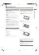
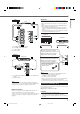
AUDIO/VIDEO CONTROL RECEIVER RX-5020VBK / RX-5022VSL L AUDIO/VIDEO CONTROL RECEIVER FM/AM TUNING FM/AM PRESET UP UP DOWN DOWN FM MODE STANDBY MASTER VOLUME MEMORY PTY–PTY SEARCH–PTY STANDBY/ON D I G I T A L SURROUND SURROUND ON/OFF FM MODE INPUT ANALOG DVD VCR TV SOUND CD TAPE/CDR FM/AM INPUT DIGITAL ADJUST SETTING INPUT ATT SURROUND MODE CONTROL DOWN UP SPEAKERS ON/OFF SOURCE NAME PHONES INSTRUCTIONS For Customer Use: Enter below the Model No. and Serial No.
Warnings, Cautions and Others/ Mises en garde, précautions et indications diverses For Canada/pour le Canada CAUTION RISK OF ELECTRIC SHOCK DO NOT OPEN CAUTION: TO PREVENT ELECTRIC SHOCK, MATCH WIDE BLADE OF PLUG TO WIDE SLOT, FULLY INSERT ATTENTION: POUR EVITER LES CHOCS ELECTRIQUES, INTRODUIRE LA LAME LA PLUS LARGE DE LA FICHE DANS LA BORNE CORRESPONDANTE DE LA PRISE ET POUSSER JUSQUAU FOND CAUTION: TO REDUCE THE RISK OF ELECTRIC SHOCK. DO NOT REMOVE COVER (OR BACK) NO USER SERVICEABLE PARTS INSIDE.
Table of Contents Table of Contents Parts Identification ...................................... 2 Getting Started ........................................... 3 Before Installation ...................................................................... 3 Checking the Supplied Accessories ........................................... 3 Putting Batteries in the Remote Control .................................... 3 Connecting the FM and AM Antennas .......................................
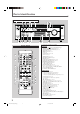
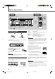
Parts Identification Front Panel 2 3 FM/AM TUNING FM/AM PRESET 1 45 7 89 6 p AUDIO/VIDEO CONTROL RECEIVER UP UP DOWN DOWN FM MODE ANALOG DIGITAL AUTO LINEAR PCM DIGITAL STANDBY MEMORY TUNED STEREO SPK L C AUTO MUTING SLEEP PRO LOGIC ΙΙ DSP H.PHONE INPUT ATT R VOLUME S.
Getting Started General Precautions • DO NOT insert any metal object into the unit. • DO NOT disassemble the unit or remove screws, covers, or cabinet. • DO NOT expose the unit to rain or moisture. Putting Batteries in the Remote Control Before using the remote control, put two supplied batteries first. • When using the remote control, aim the remote control directly at the remote sensor on the unit. 1 On the back of the remote control, remove the battery cover.
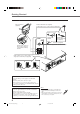
Getting Started Connecting the FM and AM Antennas AM Loop Antenna (supplied) Outdoor FM antenna (not supplied) If FM reception is poor, connect outdoor FM antenna. or 75 FMAXIAL 75 FMAXIAL CO CO Standard type outdoor FM antenna (not supplied) Supplied FM antenna ANTENNA FM 75 COAXIAL FM antenna (supplied) Extend the supplied FM antenna horizontally. Snap the tabs on the loop into the slots of the base to assemble the AM loop antenna.
After connecting the front, center, rear speakers and/or a subwoofer, set the speaker setting information properly to obtain the best possible Surround effect. For details, see pages 12 to 14. “YES” for the subwoofer and “SMALL” for the front, center and rear speakers are initial settings. To get best possible sound, change the subwoofer and speaker settings to fit your listening conditions (See pages 12 and 13). CAUTION: Use speakers with the SPEAKER IMPEDANCE indicated by the speaker terminals.
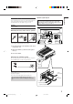
Getting Started Connecting Audio/Video Components Cassette deck or CD recorder Cassette deck Turn off all components before connections. To audio input Audio Components • CD player* • Cassette deck or CD recorder* To audio output PHONO You can connect the following audio/video components to this receiver. Refer also to the manuals supplied with your components.
VCR A C D B CD OUT (REC) MONITOR OUT TAPE CDR IN (PLAY) DVD OUT (REC) OUT (REC) VCR VCR IN (PLAY) • When connecting the DVD player or digital TV using the digital terminal, you also need to connect it to the video jack on the rear. Without connecting it to the video jack, you can view no playback picture. • After connecting the components using the DIGITAL IN terminals, set the followings correctly if necessary: – Set the digital input (DIGITAL IN) terminal setting correctly.
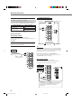
Basic Operations Front Panel Remote Control Display STANDBY lamp TV CATV A/V CONTROL RECEIVER TEST REAR L 5 4 FM/AM PRESET UP FM MODE ANALOG DIGITAL AUTO LINEAR PCM DIGITAL MEMORY DOWN DOWN TUNED STEREO SPK L C 8 10 AUTO MUTING SLEEP PRO LOGIC ΙΙ DSP H.PHONE INPUT ATT R MASTER VOLUME VOLUME S 0 9 DVD SLEEP SOUND RS CH- STANDBY/ON D I G I T A L STANDBY/ ON AUDIO 10 100 RETURN S.
You can watch picture from a video component while listening to sound from another component. Listening Only with Headphones You must turn off the speakers when you listen with headphones. 1 Connect a pair of headphones to the PHONES jack on the front Press one of the audio source selecting buttons (CD, TAPE/CDR, FM/AM), while viewing the picture from a video component such as the VCR or DVD player, etc. DVD VCR TV SOUND CD TAPE/CDR FM/AM TAPE/CDR CD DVD FM/AM TV SOUND VCR panel.
Basic Operations Turning Off the Sounds Temporarily—Muting Remote ONLY Press MUTING on the remote control to mute the sound through all speakers and headphones connected. • “MUTING” appears on the display and the volume turns off (the volume level indicator goes off). MUTING L C R S.WFR LFE S LS This receiver memorizes sound settings for each source when: • you turn off the power, • you change the source, and • you assign the source name.
Basic Settings Remote Control Display TV CATV A/V CONTROL RECEIVER TEST REAR L 4 AUDIO/VIDEO CONTROL RECEIVER REAR R 7/P FM MODE ANALOG DIGITAL AUTO LINEAR PCM DIGITAL STANDBY MEMORY DOWN DOWN TUNED STEREO SPK L C AUTO MUTING SLEEP PRO LOGIC ΙΙ DSP H.PHONE INPUT ATT R LS DVD 10 0 RETURN RS S 100 SLEEP SOUND CH- STANDBY/ON VCR SUBWOOFER 10 MASTER VOLUME VOLUME S.
Basic Settings DIGITAL AUTO : Select this for the digital input mode. The receiver automatically detects the incoming signal format. (The DIGITAL AUTO indicator lights up on the display, then the digital signal indicator for the detected signals lights up.) ANALOG : Select this for the analog input mode. (Initial setting when shipped from the factory.) If the following symptoms occur while playing Dolby Digital or DTS Digital Surround software with “DIGITAL AUTO” selected, follow the procedure below.
Speaker distance Register the sizes of all the connected speakers. • When you change your speakers, register the information about the speakers again. Register the unit you use, then the speaker distance from your listening point. • If you have set the unit before, start from step 3. 1 1 2 T SETTING Press SETTING repeatedly until “FRNT SP (Front speaker),” “CNTR SP (Center speaker)” or “REAR SP (Rear speaker)” (with the current setting) appears on the display.
Basic Settings Crossover frequency Low frequency effect attenuator Small speakers cannot reproduce the bass sounds efficiently. If you use a small speaker in any position, this receiver automatically reallocates the bass sound elements assigned to the small speaker to the large speakers. To use this function properly, set this crossover frequency level according to the size of the small speaker connected.
Sound Adjustments Display TV CATV A/V CONTROL RECEIVER 1 REAR L 5 4 UP 8 10 0 MEMORY DOWN TUNED STEREO SPK L C AUTO MUTING SLEEP PRO LOGIC ΙΙ DSP H.PHONE INPUT ATT R S.
Tuner Operations Front Panel Remote Control FM/AM FM/AM TUNING PRESET UP/DOWN UP/DOWN FM MDOE TV CATV A/V CONTROL RECEIVER TEST Display REAR L 4 TV/CATV 6 5 REAR R MENU 7/P VCR 9 8 ENTER SUBWOOFER 10 DVD 10 0 100 RETURN AUDIO/VIDEO CONTROL RECEIVER AUDIO 3 2 EFFECT 10 keys STANDBY/ON CENTER 1 SLEEP SOUND PTY–PTY SEARCH–PTY REW FF FM/AM TUNING FM/AM PRESET UP FM MODE UP ANALOG DIGITAL AUTO LINEAR PCM DIGITAL STANDBY MEMORY DOWN DOWN TUNED STEREO SPK L C AUTO
Press MEMORY again while the selected channel number is flashing on the display. Selecting the FM Reception Mode MEMORY When an FM stereo broadcast is hard to receive or noisy, you can change the FM reception mode while receiving an FM broadcast. • You can store the FM reception mode for each preset station (see page 16). The selected channel number stops flashing. The station is assigned to the selected channel number. ANALOG TUNED STEREO SPK L C AUTO MUTING R VOLUME 1 S.
Creating Realistic Sound Fields You can use the following Surround modes to reproduce a realistic sound field: ■ Dolby Surround • Dolby Pro Logic II • Dolby Digital ■ DTS Digital Surround ■ DAP (Digital Acoustic Processor) modes ■ All Channel Stereo ■ Dolby Surround Dolby Pro Logic II* Dolby Pro Logic II has a newly developed multichannel playback format to decode all 2 channel sources—regular stereo source and Dolby Surround encoded source—into 5.1 channel.
■ All Channel Stereo DAP modes have been designed to create important acoustic surround elements. This mode can reproduce a larger stereo sound field using all the connected (and activated) speakers. The sound heard in a live club, dance club, hall or pavilion consists of direct sound and indirect sound—early reflections and reflections from behind. Direct sounds reach the listener directly without any reflection.
Creating Realistic Sound Fields About Relations between Speaker Layout and Surround Modes Available Surround modes will vary depending on how many speakers are used with this receiver. Make sure that you have set the speaker information correctly (see pages 12 to 14). • If only front speakers are connected, you cannot use Surround modes. • If rear speakers are not connected, you cannot use DAP modes and All Channel Stereo.
Creating Realistic Sound Fields Before you start, remember... • Make sure that you have set the speaker information correctly (see pages 12 to 14). • You cannot adjust the center speaker output level when you have set “CNTR SP” to “NONE.” • You cannot adjust the rear speaker output levels when you have set “REAR SP” to “NONE.” • Remember not to change the speaker setting while using any Surround modes; otherwise, it may be canceled when you deactivate the speakers required for the Surround mode.
Creating Realistic Sound Fields 3 Press SOUND. SOUND 3 The 10 keys are activated for sound adjustments. 4 Press TEST to check if you can hear the sounds through all the speakers at the equal level.
Once you have adjusted the DAP modes and All Channel Stereo, the adjustment is memorized for each source. • You cannot use the DAP modes and All Channel Stereo if the rear speakers are not connected or deactivated. • You cannot adjust the effect level for “ALL CH STEREO.” From the remote control: 2 Start playing 2 channel software—either analog or Linear PCM—and select the source. 2 Press SURROUND ON/OFF to activate Surround mode.
COMPU LINK Remote Control System The COMPU LINK remote control system allows you to operate JVC’s audio components through the remote sensor on the receiver. To use this remote control system, you need to connect JVC’s audio components through the COMPU LINK-4 (SYNCHRO) jacks (see below) in addition to the connections using cables with RCA pin plugs (see page 6). • Make sure that the AC power cords of these components are unplugged before connection.
Operating JVC’s Audio/Video Components Operating Audio Components Sound Adjustment You can always perform the following operations: SURROUND ON/OFF : Turn on or off the Surround modes. SURROUND MODE : Select the Surround modes. IMPORTANT: To operate JVC’s audio components using this remote control: • You need to connect JVC’s audio components through the COMPU LINK (SYNCHRO) jacks (see page 24) in addition to the connections using cables with RCA pin plugs (see page 6).
Operating JVC’s Audio/Video Components CD changer Cassette deck After pressing CD-DISC, you can use the following buttons for CD changer operations: After pressing TAPE/CDR, you can use the following buttons for cassette deck operations: 3 : Start playback. 3 : Start playback. 4 : Return to the beginning of the current (or previous) track. FF : Fast wind the tape from left to right. REW : Fast wind the tape from right to left. ¢ : Skip to the beginning of the next track.
IMPORTANT: To operate JVC’s video components using this remote control: • Some JVC’s VCRs can accept two types of the control signals— remote code “A” and “B.” Before using this remote control, make sure that the remote control code of the VCR connected to the VCR jacks is set to code “A.” • Aim the remote control directly at the remote sensor on each component, not on the receiver.
Operating Other Manufacturers’ Video Equipment By changing the transmittable signals, you can use the remote control supplied for this unit to operate other manufacturers’ equipment. • Refer also to the manuals supplied with the other products. • To operate these components with the remote control, first you need to set the manufacturers’ codes each for TV, CATV converter, VCR and DVD player. • After replacing batteries of the remote control, set the manufacturers’ codes again.
ent To change the transmittable signals for operating a DVD player 1 Press and hold STANDBY/ON VCR. 2 Press VCR. 3 Enter manufacturer’s code using buttons 1–9, and 0. 4 Release STANDBY/ON VCR. 1 Press and hold STANDBY/ON DVD. 2 Press DVD. 3 Enter manufacturer’s code using buttons 1–9, and 0. 4 Release STANDBY/ON DVD. Now, you can perform the following operations on the VCR. STANDBY/ON VCR : Turn on or off the VCR. VCR CH +/– Now, you can use the following buttons on the DVD player.
Troubleshooting Use this chart to help you solve daily operational problems. If there is any problems you cannot solve, contact your JVC’s service center. PROBLEM POSSIBLE CAUSE SOLUTION The power does not come on. The power cord is not plugged in. Plug the power cord into an AC outlet. No sound from speakers. Speaker signal cables are not connected. Check speaker wiring and reconnect if necessary. The SPEAKERS ON/OFF button is not set correctly. Press SPEAKERS ON/OFF button correctly.
Specifications Designs & specifications are subject to change without notice. Output Power At Stereo operation: Front channels: 100 W per channel, min. RMS, driven into 8 Ω, 40 Hz to 20 kHz with no more than 0.8% total harmonic distortion. At Surround operation: Audio Audio Input Sensitivity/Impedance (1 kHz): Front channels: 100 W per channel, min. RMS, driven into 8 Ω at 1 kHz with no more than 0.8% total harmonic distortion. Center channel: 100 W, min.
Specifications FM tuner (IHF) Tuning Range: 87.5 MHz to 108.0 MHz Usable Sensitivity: Monaural: 12.8 dBf (1.2 µV/75 Ω) 50 dB Quieting Sensitivity: Monaural: Stereo: 21.3 dBf (3.2 µV/75 Ω) 41.3 dBf (31.5 µV/75 Ω) Signal-to-Noise Ratio (IHF-A weighted): Monaural: Stereo: 78 dB at 85 dBf 73 dB at 85 dBf Total Harmonic Distortion: Monaural: Stereo: 0.4% at 1 kHz 0.
Authorized Service Centers ® QUALITY SERVICE HOW TO LOCATE YOUR JVC SERVICE CENTER TOLL FREE: 1 (800) 537-5722 http://www.jvc.com Dear Customer, In order to receive the most satisfaction from your purchase, please read the instruction booklet before operating the unit. In the event that repairs are necessary, please call 1 (800)537-5722 for your nearest authorized servicer or visit our website at www.JVC.com Remember to retain your Bill of Sale for Warranty Service.
LIMITED WARRANTY AUDIO-2 JVC COMPANY OF AMERICA warrants this product and all parts thereof, except as set forth below ONLY TO THE ORIGINAL PURCHASER AT RETAIL to be FREE FROM DEFECTIVE MATERIALS AND WORKMANSHIP from the date of original retail purchase for the period as shown below. ("The Warranty Period") PARTS 2 LABOR YRS 2 YRS THIS LIMITED WARRANTY IS VALID ONLY IN THE FIFTY (50) UNITED STATES, THE DISTRICT OF COLUMBIA AND IN COMMONWEALTH OF PUERTO RICO.
VICTOR COMPANY OF JAPAN, LIMITED V EN RX-5020/5022V[J]_COVER_f J 2 01.12.
AUDIO/VIDEO CONTROL RECEIVER RECEPTEUR DE CONTROL AUDIO/VIDEO RX-5020VBK / RX-5022VSL L AUDIO/VIDEO CONTROL RECEIVER FM/AM TUNING FM/AM PRESET UP UP DOWN DOWN FM MODE STANDBY PTY–PTY SEARCH–PTY MASTER VOLUME MEMORY STANDBY/ON SURROUND ON/OFF INPUT ANALOG DVD VCR TV SOUND CD TAPE/CDR FM/AM INPUT DIGITAL ADJUST SETTING FM MODE INPUT ATT SURROUND MODE CONTROL DOWN UP SPEAKERS ON/OFF SOURCE NAME PHONES INSTRUCTIONS MANUAL D’INSTRUCTIONS For Customer Use: Enter below the Model No
Warnings, Cautions and Others/ Mises en garde, précautions et indications diverses For Canada/pour le Canada CAUTION RISK OF ELECTRIC SHOCK DO NOT OPEN CAUTION: TO PREVENT ELECTRIC SHOCK, MATCH WIDE BLADE OF PLUG TO WIDE SLOT, FULLY INSERT ATTENTION: POUR EVITER LES CHOCS ELECTRIQUES, INTRODUIRE LA LAME LA PLUS LARGE DE LA FICHE DANS LA BORNE CORRESPONDANTE DE LA PRISE ET POUSSER JUSQUAU FOND CAUTION: TO REDUCE THE RISK OF ELECTRIC SHOCK. DO NOT REMOVE COVER (OR BACK) NO USER SERVICEABLE PARTS INSIDE.
English Table of Contents Parts Identification ...................................... 2 Getting Started ........................................... 3 Before Installation ...................................................................... 3 Checking the Supplied Accessories ........................................... 3 Putting Batteries in the Remote Control .................................... 3 Connecting the FM and AM Antennas ....................................... 4 Connecting the Speakers .........
English Parts Identification Front Panel 2 3 FM/AM TUNING FM/AM PRESET 1 45 7 89 6 p AUDIO/VIDEO CONTROL RECEIVER UP UP DOWN DOWN FM MODE ANALOG DIGITAL AUTO LINEAR PCM DIGITAL STANDBY MEMORY TUNED STEREO SPK L C S VOLUME MASTER VOLUME RS CH- STANDBY/ON DVD SURROUND ON/OFF AUTO MUTING SLEEP PRO LOGIC ΙΙ DSP H.PHONE INPUT ATT R S.
Before Installation General Precautions • DO NOT insert any metal object into the unit. • DO NOT disassemble the unit or remove screws, covers, or cabinet. • DO NOT expose the unit to rain or moisture. English Getting Started Putting Batteries in the Remote Control Before using the remote control, put two supplied batteries first. • When using the remote control, aim the remote control directly at the remote sensor on the unit. 1 On the back of the remote control, remove the battery cover.
English Getting Started Connecting the FM and AM Antennas AM Loop Antenna (supplied) Outdoor FM antenna (not supplied) If FM reception is poor, connect outdoor FM antenna. or 75 FMAXIAL 75 FMAXIAL CO CO Standard type outdoor FM antenna (not supplied) Supplied FM antenna ANTENNA FM 75 COAXIAL FM antenna (supplied) Extend the supplied FM antenna horizontally. Snap the tabs on the loop into the slots of the base to assemble the AM loop antenna.
English Speaker layout diagram Connecting the Speakers After connecting the front, center, rear speakers and/or a subwoofer, set the speaker setting information properly to obtain the best possible Surround effect. For details, see pages 12 to 14. “YES” for the subwoofer and “SMALL” for the front, center and rear speakers are initial settings. To get best possible sound, change the subwoofer and speaker settings to fit your listening conditions (See pages 12 and 13).
English Getting Started Connecting Audio/Video Components Cassette deck or CD recorder Cassette deck Turn off all components before connections. To audio input Audio Components • CD player* • Cassette deck or CD recorder* To audio output PHONO You can connect the following audio/video components to this receiver. Refer also to the manuals supplied with your components.
English IMPORTANT: VCR VCR A C D B CD OUT (REC) MONITOR OUT TAPE CDR IN (PLAY) DVD OUT (REC) OUT (REC) VCR VCR IN (PLAY) • When connecting the DVD player or digital TV using the digital terminal, you also need to connect it to the video jack on the rear. Without connecting it to the video jack, you can view no playback picture.
English Basic Operations Front Panel Remote Control Display STANDBY lamp TV CATV A/V CONTROL RECEIVER TEST REAR L 5 4 FM/AM PRESET UP FM MODE ANALOG DIGITAL AUTO LINEAR PCM DIGITAL MEMORY DOWN DOWN TUNED STEREO SPK L C 8 10 AUTO MUTING SLEEP PRO LOGIC ΙΙ DSP H.
You can watch picture from a video component while listening to sound from another component. English Selecting different sources for picture and sound Listening Only with Headphones You must turn off the speakers when you listen with headphones. 1 Connect a pair of headphones to the PHONES jack on the front Press one of the audio source selecting buttons (CD, TAPE/CDR, FM/AM), while viewing the picture from a video component such as the VCR or DVD player, etc.
English Basic Operations Turning Off the Sounds Temporarily—Muting Remote ONLY Press MUTING on the remote control to mute the sound through all speakers and headphones connected. • “MUTING” appears on the display and the volume turns off (the volume level indicator goes off). MUTING L C R S.WFR LFE S LS This receiver memorizes sound settings for each source when: • you turn off the power, • you change the source, and • you assign the source name.
Front Panel English Basic Settings Remote Control Display TV CATV A/V CONTROL RECEIVER TEST REAR L 4 AUDIO/VIDEO CONTROL RECEIVER REAR R 7/P FM MODE ANALOG DIGITAL AUTO LINEAR PCM DIGITAL STANDBY MEMORY DOWN DOWN TUNED STEREO SPK L C AUTO MUTING SLEEP PRO LOGIC ΙΙ DSP H.PHONE INPUT ATT R LS DVD 10 0 RETURN RS S 100 SLEEP SOUND CH- STANDBY/ON VCR SUBWOOFER 10 MASTER VOLUME VOLUME S.
English Basic Settings DIGITAL AUTO : Select this for the digital input mode. The receiver automatically detects the incoming signal format. (The DIGITAL AUTO indicator lights up on the display, then the digital signal indicator for the detected signals lights up.) ANALOG : Select this for the analog input mode. (Initial setting when shipped from the factory.
English Speaker size Speaker distance Register the sizes of all the connected speakers. • When you change your speakers, register the information about the speakers again. Register the unit you use, then the speaker distance from your listening point. • If you have set the unit before, start from step 3. 1 1 2 T SETTING Press SETTING repeatedly until “FRNT SP (Front speaker),” “CNTR SP (Center speaker)” or “REAR SP (Rear speaker)” (with the current setting) appears on the display.
English Basic Settings Crossover frequency Low frequency effect attenuator Small speakers cannot reproduce the bass sounds efficiently. If you use a small speaker in any position, this receiver automatically reallocates the bass sound elements assigned to the small speaker to the large speakers. To use this function properly, set this crossover frequency level according to the size of the small speaker connected.
English Sound Adjustments Remote Control Front Panel Display TV CATV A/V CONTROL RECEIVER 1 REAR L 5 4 UP 8 10 0 MEMORY DOWN TUNED STEREO SPK L C AUTO MUTING SLEEP PRO LOGIC ΙΙ DSP H.PHONE INPUT ATT R S.
English Tuner Operations Front Panel Remote Control FM/AM FM/AM TUNING PRESET UP/DOWN UP/DOWN FM MODE TV CATV A/V CONTROL RECEIVER TEST Display REAR L 4 REAR R MENU 7/P FM/AM PRESET DVD 10 0 100 RETURN UP VCR 9 8 SUBWOOFER 10 FM/AM TUNING TV/CATV 6 5 ENTER AUDIO/VIDEO CONTROL RECEIVER AUDIO 3 2 EFFECT 10 keys STANDBY/ON CENTER 1 SLEEP SOUND PTY–PTY SEARCH–PTY REW FF FM MODE UP ANALOG DIGITAL AUTO LINEAR PCM DIGITAL STANDBY MEMORY DOWN DOWN TUNED STEREO SPK L
Press MEMORY again while the selected channel number is flashing on the display. Selecting the FM Reception Mode MEMORY When an FM stereo broadcast is hard to receive or noisy, you can change the FM reception mode while receiving an FM broadcast. • You can store the FM reception mode for each preset station (see page 16). The selected channel number stops flashing. The station is assigned to the selected channel number. ANALOG TUNED STEREO SPK L C AUTO MUTING R VOLUME 1 S.
English Creating Realistic Sound Fields You can use the following Surround modes to reproduce a realistic sound field: ■ Dolby Surround • Dolby Pro Logic II • Dolby Digital ■ DTS Digital Surround ■ DAP (Digital Acoustic Processor) modes ■ All Channel Stereo ■ Dolby Surround Dolby Pro Logic II* Dolby Pro Logic II has a newly developed multichannel playback format to decode all 2 channel sources—regular stereo source and Dolby Surround encoded source—into 5.1 channel.
English ■ DAP (Digital Acoustic Processor) modes ■ All Channel Stereo DAP modes have been designed to create important acoustic surround elements. This mode can reproduce a larger stereo sound field using all the connected (and activated) speakers. The sound heard in a live club, dance club, hall or pavilion consists of direct sound and indirect sound—early reflections and reflections from behind. Direct sounds reach the listener directly without any reflection.
English Creating Realistic Sound Fields About Relations between Speaker Layout and Surround Modes Available Surround modes will vary depending on how many speakers are used with this receiver. Make sure that you have set the speaker information correctly (see pages 12 to 14). • If only front speakers are connected, you cannot use Surround modes. • If rear speakers are not connected, you cannot use DAP modes and All Channel Stereo.
English Before you start, remember... • Make sure that you have set the speaker information correctly (see pages 12 to 14). • You cannot adjust the center speaker output level when you have set “CNTR SP” to “NONE.” • You cannot adjust the rear speaker output levels when you have set “REAR SP” to “NONE.” • Remember not to change the speaker setting while using any Surround modes; otherwise, it may be canceled when you deactivate the speakers required for the Surround mode.
English Creating Realistic Sound Fields 3 Press SOUND. SOUND 3 The 10 keys are activated for sound adjustments. 4 Press TEST to check if you can hear the sounds through all the speakers at the equal level.
Once you have adjusted the DAP modes and All Channel Stereo, the adjustment is memorized for each source. • You cannot use the DAP modes and All Channel Stereo if the rear speakers are not connected or deactivated. • You cannot adjust the effect level for “ALL CH STEREO.” From the remote control: 2 Start playing 2 channel software—either analog or Linear PCM—and select the source. 2 Press SURROUND ON/OFF to activate Surround mode.
English COMPU LINK Remote Control System The COMPU LINK remote control system allows you to operate JVC’s audio components through the remote sensor on the receiver. To use this remote control system, you need to connect JVC’s audio components through the COMPU LINK-4 (SYNCHRO) jacks (see below) in addition to the connections using cables with RCA pin plugs (see page 6). • Make sure that the AC power cords of these components are unplugged before connection.
You can use the remote control to operate other JVC’s components. Operating Audio Components English Operating JVC’s Audio/Video Components Sound Adjustment You can always perform the following operations: SURROUND ON/OFF : Turn on or off the Surround modes. SURROUND MODE : Select the Surround modes.
English Operating JVC’s Audio/Video Components CD changer Cassette deck After pressing CD-DISC, you can use the following buttons for CD changer operations: After pressing TAPE/CDR, you can use the following buttons for cassette deck operations: 3 : Start playback. 3 : Start playback. 4 : Return to the beginning of the current (or previous) track. FF : Fast wind the tape from left to right. REW : Fast wind the tape from right to left. ¢ : Skip to the beginning of the next track.
IMPORTANT: To operate JVC’s video components using this remote control: • Some JVC’s VCRs can accept two types of the control signals— remote code “A” and “B.” Before using this remote control, make sure that the remote control code of the VCR connected to the VCR jacks is set to code “A.” • Aim the remote control directly at the remote sensor on each component, not on the receiver.
English Operating Other Manufacturers’ Video Equipment By changing the transmittable signals, you can use the remote control supplied for this unit to operate other manufacturers’ equipment. • Refer also to the manuals supplied with the other products. • To operate these components with the remote control, first you need to set the manufacturers’ codes each for TV, CATV converter, VCR and DVD player. • After replacing batteries of the remote control, set the manufacturers’ codes again.
English ent To change the transmittable signals for operating a VCR To change the transmittable signals for operating a DVD player 1 Press and hold STANDBY/ON VCR. 2 Press VCR. 3 Enter manufacturer’s code using buttons 1–9, and 0. 4 Release STANDBY/ON VCR. 1 Press and hold STANDBY/ON DVD. 2 Press DVD. 3 Enter manufacturer’s code using buttons 1–9, and 0. 4 Release STANDBY/ON DVD. Now, you can perform the following operations on the VCR. STANDBY/ON VCR : Turn on or off the VCR.
English Troubleshooting Use this chart to help you solve daily operational problems. If there is any problems you cannot solve, contact your JVC’s service center. PROBLEM POSSIBLE CAUSE SOLUTION The power does not come on. The power cord is not plugged in. Plug the power cord into an AC outlet. No sound from speakers. Speaker signal cables are not connected. Check speaker wiring and reconnect if necessary. The SPEAKERS ON/OFF button is not set correctly. Press SPEAKERS ON/OFF button correctly.
Specifications English Designs & specifications are subject to change without notice. Amplifier Output Power At Stereo operation: Front channels: 100 W per channel, min. RMS, driven into 8 Ω, 40 Hz to 20 kHz with no more than 0.8% total harmonic distortion. At Surround operation: Audio Audio Input Sensitivity/Impedance (1 kHz): Front channels: 100 W per channel, min. RMS, driven into 8 Ω at 1 kHz with no more than 0.8% total harmonic distortion. Center channel: 100 W, min.
English Specifications FM tuner (IHF) Tuning Range: 87.5 MHz to 108.0 MHz Usable Sensitivity: Monaural: 12.8 dBf (1.2 µV/75 Ω) 50 dB Quieting Sensitivity: Monaural: Stereo: 21.3 dBf (3.2 µV/75 Ω) 41.3 dBf (31.5 µV/75 Ω) Signal-to-Noise Ratio (IHF-A weighted): Monaural: Stereo: 78 dB at 85 dBf 73 dB at 85 dBf Total Harmonic Distortion: Monaural: Stereo: 0.4% at 1 kHz 0.
VICTOR COMPANY OF JAPAN, LIMITED V EN, FR RX-5020/5022V[C]_COVER_f J 2 02.1.