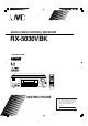
AUDIO/VIDEO CONTROL RECEIVER RX-5030VBK RX-5030V AUDIO/VIDEO CONTROL RECEIVER D I G I T A L PRO LOGIC INSTRUCTIONS For Customer Use: Enter below the Model No. and Serial No. which are located either on the rear, bottom or side of the cabinet. Retain this information for future reference. Model No. Serial No. LVT0984-011A [UJ] Cover_RX-5030VBK[UJ]f 3 03.5.
Warnings, Cautions, and Others Caution –– STANDBY/ON switch! Disconnect the mains plug to shut the power off completely. The switch in any position does not disconnect the mains STANDBY/ON line. The power can be remote controlled. CAUTION To reduce the risk of electrical shocks, fire, etc.: 1. Do not remove screws, covers or cabinet. 2. Do not expose this appliance to rain or moisture. CAUTION • Do not block the ventilation openings or holes.
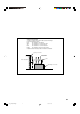
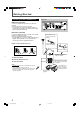
Caution: Proper Ventilation To avoid risk of electric shock and fire and to protect from damage. Locate the apparatus as follows: Front: No obstructions open spacing. Sides: No obstructions in 10 cm from the sides. Top: No obstructions in 10 cm from the top. Back: No obstructions in 15 cm from the back. Bottom: No obstructions, place on the level surface. In addition, maintain the best possible air circulation as illustrated.
Before Installation Precautions Checking the Supplied Accessories General precautions • DO NOT insert any metal object into the unit. • DO NOT disassemble the unit or remove screws, covers, or cabinet. • DO NOT expose the unit to rain or moisture. Check to be sure you have all of the following supplied accessories. The number in parentheses indicates the quantity of each piece supplied.
Table of Contents Parts Identification ...................................... 3 Tuner Operations ....................................... 20 Getting Started ........................................... 5 Setting the AM Tuner Interval Spacing ........................... 20 Tuning in to Stations Manually ........................................ 20 Using Preset Tuning ....................................................... 20 Connecting the AM and FM Antennas .............................
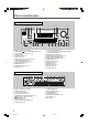
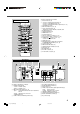
Parts Identification Front Panel 6 5 1 2 34 789 p MASTER VOLUME RX–5032V AUDIO/VIDEO CONTROL RECEIVER STANDBY SURROUND DIMMER DSP INPUT DIGITAL SURROUND/DSP OFF INPUT ANALOG STANDBY/ON INPUT ATT DVD TV SOUND VCR CD TAPE/CDR FM/AM SETTING MULTI JOG ADJUST SOURCE NAME PHONES D I G I T A L PRO LOGIC SPEAKERS SUBWOOFER OUT ON/OFF ON/OFF w e q FM/AM TUNING t r See pages in parentheses for details.
See pages in parentheses for details.
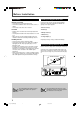
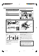
Getting Started Connecting the AM and FM Antennas Rear panel AM antenna connection Connect the supplied AM loop antenna to the AM LOOP terminals. Turn the loop until you have the best reception. • If the reception is poor, connect an outdoor single vinylcovered wire (not supplied) to the AM EXT terminal. (Keep the AM loop antenna connected.) FM antenna connection Connect the supplied FM antenna to the FM 75 Ω COAXIAL terminal as a temporary measure. Extend the supplied FM antenna horizontally.
Connecting the Speakers and Subwoofer 7 Speaker layout diagram You can connect five speakers—a pair of front speakers, a center speaker, and a pair of surround speakers—and a subwoofer. Center speaker Left front speaker CAUTION: Use speakers with a SPEAKER IMPEDANCE as indicated by the speaker terminals.
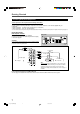
Getting Started Connecting Audio/Video Components Turn the power off to all components before making connections. You can connect the following audio/video components to this receiver. Refer also to the manuals supplied with your components. • Audio Components: CD player* and Cassette deck (or CD recorder*) • Video Components: VCR, TV*, and DVD player* *You can connect these components using the methods described in “Analog Connections” (below) and/or in “Digital Connections” (see page 9).
Video component connections TV Use cables with RCA pin plugs (not supplied). Connect the white plug to the audio left jack, the red plug to the audio right jack, and the yellow plug to the video jack.
Getting Started Digital Connections Connecting the Power Cord This receiver is equipped with two DIGITAL IN terminals—one digital coaxial terminal and one digital optical terminal. You can connect any component to one of the digital terminals using a digital coaxial cable (not supplied) or digital optical cable (not supplied). Before plugging the power cord into an AC outlet, make sure that all connections have been made. Plug the power cord into an AC outlet.
Basic Operations Front panel Remote control STANDBY/ON and STANDBY lamp A/V CONTROL RECEIVER 1 RX–5032V AUDIO/VIDEO CONTROL RECEIVER 2 4 5 6 7/P 8 9 0 10 10 STANDBY/ON AUDIO 3 TA/NEWS/INFO DISPLAY MODE Source selection buttons Source selection buttons SOURCE NAME Notes: Turning On the Power Press STANDBY/ON (or STANDBY/ON AUDIO on the remote control). The STANDBY lamp goes off. The name of the current source (or station frequency) appears on the display.
Basic Operations Front panel Remote control DIMMER MASTER VOLUME control TA/NEWS/INFO SLEEP DISPLAY MODE RX–5032V AUDIO/VIDEO CONTROL RECEIVER Audio source selection buttons DIMMER MUTING VOLUME +/– PHONES jack SPEAKERS ON/OFF Audio source selection buttons Selecting Different Sources for Picture and Sound You can watch the picture from a video component while listening to sound from another component.
Basic Operations After using the headphones 1 Press SPEAKERS ON/OFF on the front panel to activate the speakers. The H.PHONE indicator goes off and the SPK indicator lights up. 2 Disconnect the headphones. CAUTION: Be sure to turn down the volume • Before connecting or putting on headphones, as high volume can damage both the headphones and your hearing. • Before turning on speakers again, as high volume may be output from the speakers. Changing the Display Brightness— DIMMER You can dim the display.
Basic Settings Basic Settings Using MULTI JOG Dial 4 Turn MULTI JOG dial to adjust the selected item. Select “SUBWOOFER YES” if a subwoofer is connected. After connecting and placing speakers, you need to make basic settings for the following items according to your listening conditions. • Speaker information (see the right column and page 14) • Digital input terminal sources (see page 14) Ex.: When “SUBWOOFER YES” is selected. 7 Operating buttons 5 Press EXIT.
Basic Settings 7 Speaker distance—DISTANCE UNIT, FRNT (Front) DISTANCE, CNTR (Center) DISTANCE, SURR (Surround) DISTANCE Select the unit to measure the distance between your listening position and speakers—“METER” or “FEET.” After selecting the measuring unit, select the appropriate speaker distance for each speaker within the range of “0.3m” (“1FT”) to “9.0m” (“30FT”) by 0.3 m (1 foot) step. Example:In this case, set “FRNT DISTANCE” to “3.0m” (“10FT”), “CNTR DISTANCE” to “2.
Basic Settings Front panel Remote control TA/NEWS/INFO INPUT DIGITAL DISPLAY MODE RX–5032V AUDIO/VIDEO CONTROL RECEIVER Source selection buttons ANALOG/DIGITAL D I G I T A L D I G I T A L SURROUND PRO LOGIC Source selection buttons INPUT ANALOG Selecting the Analog or Digital Input Mode When you have connected digital source components using both the analog connection (see pages 7 and 8) and the digital connection (see page 9) methods, you need to select the input mode correctly.
Sound Adjustments Front panel INPUT ATT RX–5032V DIGITAL AUTO ANALOG LINEAR PCM DIGITAL AUDIO/VIDEO CONTROL RECEIVER SPK 1 2 ONE TOUCH OPERATION L PRO LOGIC DSP H.PHONE AUTO MUTING TUNED STEREO TA NEWS INFO VOLUME C R BASS BOOST INPUT ATT EON RDS SLEEP S.WFR LFE LS S RS CH– SUBWOOFER OUT ON/OFF Attenuating the Input Signal Remote NOT When the input level of the analog source is too high, the sound will be distorted.
Sound Adjustments Sound Adjustments Using MULTI JOG Dial 7 Operating procedure Ex. When adjusting the bass sound You can adjust the sound using MULTI JOG dial on the front panel. • Tone—BASS, TREBLE • Subwoofer output level*—SUBWFR LEVEL • Speakers’ output level*— FRONT L/R LEVEL, CENTER LEVEL, SURR L/R LEVEL • Effect level for DAP modes—EFFECT • Panorama control for Pro Logic II Music—PANORAMA CTRL Before you start, remember... There is a time limit in doing the following steps.
Sound Adjustments 7 Tone—BASS, TREBLE Adjust the bass and treble sounds as you like (–10 dB to +10 dB in 2 step intervals). • “0” is the initial setting. 7 Subwoofer output level—SUBWFR (Subwoofer) LEVEL Adjust the subwoofer output level (–10 dB to +10 dB in 1 step intervals). • “0” is the initial setting. Note: Subwoofer output level cannot be adjusted in the following cases: • When “SUBWOOFER NO” is selected for the subwoofer setting (see page 13). • When the HEADPHONE mode is in use (see page 11).
Sound Adjustments 2 Press TEST. Adjusting Subwoofer Output Level “TEST TONE L” starts flashing on the display and a test tone comes out of the speakers in the following order: Make sure the subwoofer setting is set to “YES” (see page 13). 1 Press SOUND. The 10 keys are activated for sound adjustments.
Tuner Operations Front panel Remote control STANDBY/ON FM/AM RX–5032V DISPLAY MODE AUDIO/VIDEO CONTROL RECEIVER FM/AM FM/AM TUNING 5/∞ FM/AM PRESET 5/∞ MEMORY Notes: Setting the AM Tuner Interval Spacing Remote NOT Some countries space AM stations 9 kHz apart, and other countries use 10 kHz spacing. 9 kHz spacing is the initial setting. To select the 10 kHz interval: Be sure the receiver is turned off, but is plugged into an AC outlet. .
Tuner Operations Front panel Remote control A/V CONTROL RECEIVER FM/AM RX–5032V 10 keys AUDIO/VIDEO CONTROL RECEIVER DISPLAY MODE FM/AM PRESET 5/∞ 4 FM MODE FM/AM MEMORY Press MEMORY again while the selected channel number is flashing on the display. The selected channel number stops flashing. The station is assigned to the selected channel number.
Creating Realistic Sound Fields You can use the following Surround and DSP modes to reproduce a realistic sound field: Surround modes 7 Dolby • Dolby Pro Logic II • Dolby Digital 7 DTS Digital Surround DSP modes Dolby Digital 5.1 channel encoding method (so-called discrete multi-channel digital audio format) records and digitally compresses the left front channel, right front channel, center channel, left surround channel, right surround channel, and LFE channel signals.
Creating Realistic Sound Fields DSP modes Creating sound field 7 DAP (Digital Acoustic Processor) modes Reflections from behind DAP modes have been designed to create important acoustic surround elements. Early reflections The sound heard in a live club, dance club, hall or pavilion consists of direct sound and indirect sound—early reflections and reflections from behind. Direct sounds reach the listener directly without any reflection.
Creating Realistic Sound Fields Make sure that you have set the speaker information correctly (see pages 13 and 14). • If only the front speakers are connected, you cannot use Surround/DSP modes. • You cannot use DSP modes if no surround speakers are connected. • Do not change the speaker setting while using any Surround/DSP modes; otherwise, the Surround/DSP modes may be canceled when you deactivate the speakers required for the Surround/DSP modes.
Creating Realistic Sound Fields 7 Adjustable items and selected Surround/DSP mode Using DSP Modes • For adjustment operation, see pages 17 to 19. Speaker layouts required for the DSP modes are as follows: • 5 channels (Front, center, and surround speakers are connected.
COMPU LINK Remote Control System The COMPU LINK remote control system allows you to operate JVC’s audio components through the remote sensor on the receiver. To use this remote control system, you need to connect JVC’s audio components through the COMPU LINK (SYNCHRO) jacks (see below) in addition to the connections using cables with RCA pin plugs (see page 7). • Make sure that the AC power cords of these components are unplugged before connection.
AV COMPU LINK Remote Control System The AV COMPU LINK remote control system allows you to operate JVC’s video components (TV, VCR, and DVD player) through the receiver. To use this remote control system, you need to connect the video components you want to operate following the diagrams and the procedure below.
The AV COMPU LINK remote control system allows you to use the five basic functions listed below. Remote Control of the TV, DVD player, and VCR using this Remote Control See page 31 for details. • Aim the remote control directly at the remote sensor on each target component. Automatic Selection of the TV Input Mode • When you select “TV SOUND” as the source to play on the receiver, the TV automatically changes the input mode to the TV tuner so that you can watch TV.
Operating JVC’s Audio/Video Components You can use the remote control to operate other JVC components. Sound Adjustment You can always use the following buttons: SURROUND Turn on and select the Surround modes. IMPORTANT: DSP Turn on and select the DSP modes. To operate JVC’s audio components using this remote control: • You need to connect JVC’s audio components through the COMPU LINK (SYNCHRO) jacks (see page 26) in addition to the connections using cables with RCA pin plugs (see page 7).
CD player Cassette deck After pressing CD, you can use the following buttons for the CD operations: After pressing TAPE/CDR, you can use the following buttons for the cassette deck operations: 3 Start playback. 3 Start playback. 4 Return to the beginning of the current (or previous) tracks. FF Fast wind a tape from left to right. REW Fast wind a tape from right to left. ¢ Skip to the beginning of the next tracks. 7 Stop playback or recording. 7 Stop playback. 8 Pause playback.
Operating JVC’s Audio/Video Components Operating Video Components VCR You can always use the following buttons: IMPORTANT: STANDBY/ON To operate JVC’s video components using this remote control: • You need to connect JVC’s video components through the AV COMPU LINK terminals (see page 27) in addition to the connections using cables with RCA pin plugs (see page 8). • Some JVC VCRs can accept two types of control signals—remote code “A” and “B.
Operating Other Manufacturers’ Video Equipment By changing the transmission signals, you can use the remote control supplied for this unit to operate other manufacturers’ equipment. • Refer also to the manuals supplied for the other products. • To operate these components with the remote control, first you need to set the manufacturers’ code each for TV, CATV converter, VCR and DVD player. • When replacing the batteries in the remote control, set the manufacturers’ codes again.
Operating Other Manufacturers’ Video Equipment To change the transmission signals for operating a VCR To change the transmission signals for operating a DVD player 1 Press and hold STANDBY/ON VCR. 2 Press VCR. 3 Enter manufacturer’s codes using buttons 1 – 9, and 0. 4 Release STANDBY/ON VCR. 1 Press and hold STANDBY/ON DVD. 2 Press DVD. 3 Enter manufacturer’s codes using buttons 1 – 9, and 0. 4 Release STANDBY/ON DVD. Now, you can perform the following operations on the VCR.
Troubleshooting Use this chart to help you solve daily operational problems. If there is any problem you cannot solve, contact your JVC service center. PROBLEM POSSIBLE CAUSE SOLUTION The power does not come on. The power cord is not plugged in. Plug the power cord into an AC outlet. No sound from speakers. Speaker signal cables are not connected. Check speaker wiring and reconnect if necessary. An incorrect source is selected. Select the correct source. Muting is activated.
Specifications Designs & specifications are subject to change without notice. Amplifier Output Power: At Stereo operation: 100 W* per channel, min. RMS, driven into 8 Ω at 1 kHz with no more than 0.9% total harmonic distortion. (IEC268-3/DIN) Front channels: At Surround operation: Front channels: 100 W per channel, min. RMS, driven into 8 Ω at 1 kHz with no more than 0.8% total harmonic distortion. Center channel: 100 W, min. RMS, driven into 8 Ω at 1 kHz, with no more than 0.
Specifications FM tuner (IHF) Tuning Range: 87.50 MHz to 108.00 MHz Usable Sensitivity: Monaural: 17.0 dBf (1.95 µV/75 Ω) 50 dB Quieting Sensitivity: Monaural: 21.3 dBf (3.2 µV/75 Ω) Stereo: 41.3 dBf (31.5 µV/75 Ω) Monaural: 78 dB at 85 dBf Stereo: 73 dB at 85 dBf Monaural: 0.4% at 1 kHz Stereo: 0.
AUDIO/VIDEO CONTROL RECEIVER VOLTAGE SELECTOR 110V 220V 127V 230 - 240V VOLTAGE SELECTOR 110V 220V 127V 230 - 240V CAUTION for mains (AC) line BEFORE PLUGGING IN, do check that your mains (AC) line voltage corresponds with the position of the voltage selector switch provided on the outside of this equipment and, if different, reset the voltage selector switch, to prevent from a damage or risk of fire/electric shock.