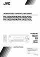
AUDIO/VIDEO CONTROL RECEIVER RX-6030VBK/RX-6032VSL RX-5030VBK/RX-5032VSL AI/fbf'tllll211 _W I IAIW" _flvlrlkw J J_llWJflk _P'tBBnl _flflr oQ dv_ o l I IW v hllVB_k DIGITAL o o o @U m °O o SURROUND °o DIGITAL _llle] • _slCll_ Ill INSTRUCTIONS For Customer Use: Enter below the Model No. end Serial No. which ere located either on the rear, bottom or side of the cabinet. Retain this information for future reference. Model No. Serial No.
For U.S.A CAUTION: TO REDUCE THE RISK OF ELECTRIC SHOCK. DO NOT REMOVE COVER {OR BACK) NO USER SERVICEABLE PARTS INSIDE. REFER SERVICING TO QUALIFIED SERVICE PERSONNEL. The lightning flash with arrowhead symbol, within an equilateral triangle is intended to alert the user to the presence of uninsulated "dangerous voltage" within the product's enclosure that may be of sufficient magnitude to constitute a risk of electric shock to persons.
Parts Getting Identification Started ...................................... 2 ........................................... 5 Checking the Supplied Accessories ................................. 5 Connecting the AM and FM Antennas ............................. 5 Connecting the Speakers and Subwoofer ........................ 6 Connecting Audio/Video Components .............................. 7 Analog Connections ................................................................. 7 Digital Connections .......
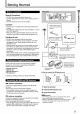
RX-6030VBK is mainly used for illustrations to explain the connections and operations throughout the instructions. See pages in parentheses for details. I1_ STANDBY/ON _/I button and STANDBY lamp (11 ) I_ SURROUND/DSP OFF button (26, 27) I_1 DSP button (27) 141 SURROUND button (26) 151 Remote sensor (10) 161 Display (For details, see "Display" on the next page.
m E See pages in parentheses for details. Q_ ANALOG indicator (17) _2_ DIGITAL AUTO indicator (17) _3_SPK indicator (13) _4_Speaker indicators and signal indicators (27) _5_1"3['1PRO LOGIC II indicator (24, 26) _6_ DSP indicator (25, 27) _7_ H.
Rear PaneI--RX-6030VBK/RX-6032VSL Rear PaneI--RX-5030VBK/RX-5032VSL See pages in parentheses for details. See pages in parentheses for details.
I General Precautions =. • DO NOT insert any metal object into the unit. • DO NOT disassemble the unit or remove screws, covers, or cabinet. • DO NOT expose the unit to rain or moisture. Locations • Install the unit in a location that is level and protected from moisture. • The temperature around the unit must be between -5°C and 35°C (23"F and 95"F). • Make sure there ls good ventilation around the unit. Poor ventilation could cause overheating and damage the unit.
• Speaker layout diagram You can connect five speakers--a pair of front speakers, a center speaker, and a pair of surround speakers--and a subwoofer. CAUTION: Usespeakers with a SPEAKER IMPEDANCE as indicated by the speaker terminals.
m _--% == Turn the power off to all components before making connections. You can connect the following audio/video components to this receiver. Refer also to the manuals supplied with your components. • Audio Components: CD player _ and Cassette deck (or CD recorder s) • Video Components: VCR, TV_, and DVD player _ Youcan connect these components using the methods described in "Analog connections" (below) and/or in "Digital connections" (see page 10).
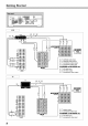
Getting Started ® oo iii VCR IX] To To To To VCR ....
m DVD RX-6030VBKiRX-6032VSL €81 /A1 To To To To To To To surround left/right audio output center audio output subwoofer audio output front left/right audio output composite video output S-video output component video output $U8 • To use software encoded with Dolby Digital or DTS Digital Surround, connect the DVD player using one of the DIGITAL IN terminals (see page 10). • When you connect the DVD player with stereo output jacks, connect using _.
Digital Connections This receiver is equipped with two DIGITAL IN terminals_ne digital coaxial terminal and one digital optical terminal. You can connect any component to one of the digital terminals using a digital coaxial cable (not supplied) or digital optical cable (not supplied). Before plugging the power cord into an AC outlet, make sure that all connections have been made. Plug the power cord into an AC outlet.
m F_ Remote control STANDBY/ON Oil and STANDBY lamp Q Q'Q_ ',Q Q Q,'<_ L STANDBY/ON d_/I AUDIO ® I:1 t#l QQO_ o o .......... o O O o ° L ° • _ °O o =_,. °o 5" @@@@ Source selection buttons |t!_l ,---_ Source selection buttons oooo TAPE/CDR_: Select the cassette deck (or the CD recorder). FM (front panel): Select an FM broadcast. AM (front panel): Select an AM broadcast. FM/AM _ (remote control): Select an FM or AM broadcast.
Basic Operations F_ Remotecontrol MASTER VOLUME control DIMMER Audio source selection -_buttons DIMMER -PHONES SPEAKERS SOURCE jack ON/OFF (TAPE/CDR) NAME selection buttons You can watch the picture from a video component while listening to sound from another component. Press one of the audio source selection buttons while RX-6030VBK/RX-6032VSL RX-5030VBK/RX-5032VSLI _ I .....
m After using the headphones On the front panel To increase the volume, turn MASTER VOLUME control clockwise. To decrease the volume, turn MASTER VOLUME control counterclockwise. 1 Press SPEAKERS ON/OFF on the front panel to activate the speakers. The H.PHONE indicator goes off and the SPK indicator lights up. 2 Disconnect the headphones. == CAUTION: From the remote control Be sure to turn down the volume To increase the volume, press VOLUME +. To decrease the volume, press VOLUME -.
Basic Operations Basic adjustment auto memory You can fall asleep while listening to music--Sleep (Z) ._c_. Timer. #311 Q Q'Q_ '_ Q Q QvQQ13 ®4 @U (J_J @ _ -- SLEEP This receiver memorizes sound settings for each source when--: • you turn off the power, • you change the source, and • you assign the source name. When you change the source, the memorized settings for the newly selected source are automatically recalled.
After connecting and placing speakers, you need to make basic settings for the following items according to your listening conditions. • Speaker information (see the next column and page 16) • Digital input terminal sources (see page 16) • RX-6030VBK and RX-6032VSL only: Video input terminal type (see page 16) 4 Turn MULTI JOG dial to adjust the selected item. Select "SUBWOOFERYES" if a subwoofer is connected. -= []SU]]H00FER YES m o == Ex.:When "SUBWOQFERYES" is selected. Press EXIT.
Basic Settings • Speaker distance---DISTANCE UNIT, FRNT DISTANCE, CNTR DISTANCE, SURR DISTANCE Select the unit to measure the distance between your listening position and speakers--"METER" or "FEET." After selecting the measuring unit, select the appropriate speaker distance for each speaker within the range of "0.3m" ("1FT") to "9.0m" ("3OFT") by 0.3 m (1 foot) step. Example: Inthiscase, set"FRNTDISTANCE"te"3.0m"("lOFT"), "CNTR DISTANCE" to "2.7m" ("9FT"), and "SURR DISTANCE" to "2.4m" ("SFT").
m F_ €€1 a Remotecontrol I/i INPUT DIGITAL €I €€1 Source selection buttons INPUT ANALOG When you have connected digital source components using both the analog connection (see pages 7 - 9) and the digital connection (see page 10) methods, you need to select the input mode correctly. Press one of the source selection buttons-- DVD, TV SOUND, CD, or TAPE/CDR*--for which you want to change the input mode.
F_ Remotecontrol INPUT ATT ADJUST .J_ ooo o o ooo o BASSBOOST dVC aEMOTECONTaO_ m_ SUBWOOFER OUT ON/OFF IT MULTI JOG dial Notes: When the input level of the analog source is too high, the sound will be distorted. If this happens, you need to attenuate the input signal level to prevent the distortion. Once this has been adjusted, this receiver memorizes the adjustment for each source. Press and hold INPUT ATT on the front panel so that the INPUT ATT indicator lights up on the display.
m 2 Turn MULTI JOG dial to select an item you want to adjust. You can adjust the sound using MULTI JOG dial on the front panel. • Tone--BASS+ TREBLE • Subwoofer output leveI_--SUBWFR LEVEL • Speakers' output level +FRONT L!R LEVEL, CENTER LEVEL, SURR L!R LEVEL • Effect level for DAP modes--EFFECT • Panorama control for Pro Logic II Music--PANORAMA CTRL +You can also use the remote control to adjust these items (see pages 20 and 21 ).
• Tone--BASS,TREBLE • Adjust the bass and treble sounds as you like (-10 to +10 in 2 step intervals). • "0" is the initial setting. • Subwoofer output leveI--SUBWFR LEVEL Adjust the subwoofer output level (-10 to +10 in 1 step interval). • "0" is the initial setting. Panorama control for Pro Logic II Music-PANORAMA CTRL You can turn on or off the Panorama control for Pro Logic II Music only when "PL II MUSIC" is activated.
I Press SOUND. m Press TEST again to stop the test tone. O The 10 keys are activated for sound adjustments. 2 Press TEST. € =3 Adjusting "TEST TONE U'starts flashing on the display and a test tone comes out of the speakers in the following order: Subwoofer Output Level € Make sure the subwoofer is set to "YES" (see page 15). I Press SOUND. =3 The 10 keys are activated for sound adjustments. iTE5T TONE ,._ Press SUBWFR. 3 Press LEVEL +/- to adjust the subwoofer output level (-10 to +10).
F_ Remotecontrol V (Z 3 "_c_" Oii iiil 10 keys ---- _®_ FM/AM -- ooo FM/AM TUNING A/V i iTI_TI_j hil [_ I-._ FM/AM PRESET A/V FM MODE MEMORY FM MODE -- @ooo oooo hV_ Ftl"_!lfflI _vj Once a station is assigned to a channel number, the station can be quickly tuned in.You can preset up to 30 FM and 15 AM stations. I Select the band (FM or AM). RX-6030VBI(/RX-6032VSL Press FM or AM on the front panel. The last received station of the selected band is tuned in.
m 3 Press FM/AM PRESET A/v to select a channel number while the channel number position 1 Press is flashing. . ,_: 8]5 I'IHZ20 Ex.: When channel number '*3"is selected. 4 Press MEMORY From the remote control again while the selected channel number is flashing on the display. The selected channel number stops flashing. The station is assigned to the selected channel number. FM/AM to select the band (FM or AM).
You can use the following Surround and DSP modes to reproduce a realistic sound field: Surl"ound•odes • Doiby • Dolby Pro Logic II • Dolby Digital • DTS Digital Surround DSP •odes • DAP modes • All Channel Stereo Dolby Digital 5.1 channel encoding method (so-called discrete multi-channel digital audio format) records and digitally compresses the left front channel, right front channel, center channel, left surround channel, right surround channel, and LFE channel signals.
m DSP•odes • DAP (Digital Acoustic Processor) modes DAP modes have been designed to create important acoustic surround elements. Reflections from behind _ Early - J f The sound heard in a live club, dance club, hall or pavilion consists of direct sound and indirect sound---early reflections and reflections from behind. Direct sounds reach the listener directly without any reflection.
Creating Realistic Sound Fields F_ Remotecontrol DSP SURROUND --DSP SURROUND E i oooo -----SURROUND/DSP OFF II t________! SURROUND/DSP OFF 2 Press SURROUND, Speaker layouts required for Surround modes are as follows: • 5 channels (Front, center, and surround speakers are connected.) • 4 channels (Front and surround speakers are connected.) • 3 channels (Front and center speakers are connected.) The appropriate Surround mode will be activated according to the incoming signal.
• Adjustable items and selected Surround/DSP m mode • For adjustment operation, see pages 19 to 21. Speaker layouts required for the DSP modes are as follows: • 5 channels Selected Surround/ DSP mode Adjustable items -_ Adjustable range == == (Front, center, and surround speakers are connected.) _. 0 • 4 channels (Front and surround speakers are connected.
This section is ONLY for RX-6030VBK and RX-6032VSL From the remote control This receiver provides the DVD MULTI playback mode for reproducing the analog discrete output mode of the DVD player. Before playing a DVD, refer also to the manual supplied with the DVD player. r_'_j %J (Z) _c_ O/I Q Q,Q_ ® I,]VA,] I_,_LtJkllI-..,l I_"_)_,'_J _ _'_l'_':_ @G?@_ _®_ -- DVD MULTI 0000 Onthefront panel Press DVD MULTI. oooE,1O!oo - I1L'II I'IULTI u.
The COMPU LINK remote control system allows you to operate JVC's audio components through the remote sensor on the receiver. To use this remote control system, you need to connect JVC's audio components through the COMPU LINK-4 (SYNCHRO) jacks (see below) in addition to the connections using cables with RCA pin plugs (see page 7). • Make sure that the AC power cords of these components are unplugged before connection. Plug in the AC power cords only after all other connections are completed.
The AV COMPU LINK remote control system allows you to operate JVC's video components (TV, VCR, and DVD player) through the receiver. To use this remote control system, you need to connect the video components you want to operate following the diagrams below and the procedure on the next page. RX-6030VBKiRX-6032VSL This receiver is equipped with the AV COMPU LINK-IlL which added a function to operate JVC's video components component video terminals. through the • AV COMPU LINK Connection ..........
I Notes: One-Touch DVDPlay • When connecting only the VCR or DVD player to this receiver, connect it directly to the receiver using cables with the monaural mini-plugs. • Make sure that the remote control code of the VCR connected to the Simply by starting playback on the DVD player, you can view the DVD playback without setting other switches manually.
You can use the remote control to operate other JVC components. Sound Adiustment You can always use the following buttons: SURROUND Turn on and select the Surround modes. IM PORTANT: DSP Turn on and select the DSP modes. To operate JVC's audio components using this remote control: • You need to connect JVC's audio components through the COMPU LINK-4 (SYNCHRO) jacks (see page 29) in addition to the connections using cables with RCA pin plugs (see page 7).
m 0 Cassette deck After pressing CD, you can use the following buttons for the CD operations: After pressing TAPE/CDR, you can use the following buttons for the cassette deck operations: Start playback. 1<41 Start playback. Return to the beginning of the current (or previous) tracks. FF Fast wind a tape from left to right. REW Fast wind a tape from right to left. Skip to the beginning of the next tracks. • Stop playback or recording. II Pause playback. To release, press D,-.
Operating JVC's Audio/Video Components VCR You can always use the following buttons: IM PORTANT: STANDBY/ON To operate JVC's video components using this remote control: • You need to connect JVC's video components through the AV DOMPU LiNK terminals (see page 30) in addition to the connections using cables with RDA pin ptugs (see pages B end 9). • Some JVC VCRs can accept two types of contrel signals--remote code "A" and "B.
By changing the transmission signals, you can use the remote control supplied for this unit to operate other manufacturers' equipment. • Refer also to the manuals supplied for the other products. • To operate these components with the remote control, first you need to set the manufacturers' code each for TV, CATV converter, VCR and DVD player. • When replacing the batteries in the remote control, set the manufacturers' codes again. To change the transmission operating a TV ! Set TV/CATV 2 to "TV.
To change the transmission operating a VCR ! 2 Press and hold STANDBY/ON ®/i VCR. Press VCR. To change the transmission operating a DVD player ! signals for Press and hold STANDBY/ON (b/i DVD. 2 Press DVD. 3 Enter manufacturer's 1 - 9, and O. 4 signals for codes using buttons Release STANDBY/ON O/i VCR. Now, you can perform the following operations on the VCR. STANDBY/ON _)/I VCR Turn on or off the VCR. VCR OH +/- Change the channels. 3 Enter manufacturer's 1 - 9, and O.
Use this chart to help you solve daily operational problems. If there is any problem you cannot solve, contact your JVC service center. PROBLEM POSSIBLE CAUSE SOLUTION The power does not come on. The power cord is not plugged in. Plug the power cord into an AC outlet. No sound from speakers. Speaker signal cables are not connected. Check speaker wiring and reconnect if necessary. An incorrect source is selected. Select the correct source. Muting is activated.
RX-6030VBK/R_6032VSL Amplifier Output Power: At Stereo operation: Front channels: At Surround operation: Front channels: Center channel: Surround channels: 100 W per channel, rain. RMS, driven 20 kHz with no more than 0.8% total distortion. into 8 £, 40 Hz to harmonic 100 W per channel, min. RMS, driven into 8 _ at 1 kHz with no more than 0.8% totat harmonic distortion. 100 W, min. RMS, driven into 8 _ at 1 kHz, with no more than 0.8% total harmonic distortion. 100 W per channel, min.
I RX-5030VBK/RX-5032VSL [_ Amplifier Output Power: At Stereo operation: Front channels: At Surround operation: Front channels: Center channel: Surround channels: 100 W per channel, min. RMS, driven into 8 _, 40 Hz to 20 kHz with no more than 0.8% total harmonic distortion. 100 W per channel, min. RMS, driven into 8 _ at 1 kHz with no more than 0.8% total harmonic distortion. 100 W, rain. RMS, driven into 8 _2 at 1 kHz, with no more than 0.8% total harmonic distortion. 100 W per channel, min.
:JVC * * * . LIMITED WARRANTY ** AUDI0-2 * JVC COMPANY OF AMERICA warrants this product and all parts thereof, except as set forth below ONLY TO THE ORIGINAL PURCHASER AT RETAIL to be FREE FROM DEFECTWE MATERIALS AND WORKMANSHIP from the date of original retail purchase for the period as shown below. ("The Warranty Period") _t PARTS . LABOR 2 YRS 2 YRS * * . * * THIS LIMITED WARRANTY IS VALID ONLY _N THE FIFTY (50) UNITED STATES, THE DISTR_CT OF COLUMBIA IN COMMONWEALTH OF PUERTO RICO.
Authorized Service Centers QUALITY JVC ° SERVICE HOW TO LOCATE YOUR JVC SERVICE CENTER TOLL FREE: 1 (800) 537-5722 http://www.jvc.com Dear Customer, In order to receive the most satisfaction from your purchase,please read the instruction booklet before operating the unit.In the event that repairs are necessary, please call 1 (800)537-5722 for your nearest authorized servicer or visit our website at www.JVC.eom Remember to retain your Bill of Sale for Warranty Service.
! Warnings, Cautiens, and Others/ Mises en garde, pr6cautions et indications diverses For U.S.A CAUTION: TO REDUCE THE RISK OF ELECTRIC SHOCK. DO NOT REMOVE COVER (OR BACK) NO USER SERVICEABLE PARTS INSIDE. REFER SERVICING TO QUALIFIED SERVICE PERSONNEL.
Parts Identification Getting Started ...................................... 2 ........................................... 5 Checking the Supplied Accessories ................................. 5 Connecting the AM and FM Antennas ............................. 5 Connecting the Speakers and Subwoofer ........................ 6 Connecting Audio/Video Components .............................. 7 Analog Connections ................................................................. 7 Digital Connections .....
Parts RX-6030VBK |dentification is mainly used for illustrations to explain the connections See pages in parentheses for details. I1_ STANDBY/ON _/I button and STANDBY lamp (11 ) I_ SURROUND/DSP OFF button (26, 27) I_1 DSP button (27) 141 SURROUND button (26) 151 Remote sensor (10) 161 Display (For details, see "Display" on the next page.
/ See pages in parentheses for details. Q_ ANALOG indicator (17) _2_ DIGITAL AUTO indicator (17) _3_SPK indicator (13) _4_Speaker indicators and signal indicators (27) _5_1"3['1PRO LOGIC II indicator (24, 26) _6_ DSP indicator (25, 27) _7_ H.
Rear PaneI--RX-6030VBK/RX-6032VSL Rear PaneI--RX-5030VBK/RX-5032VSL See pages in parentheses for details. See pages in parentheses for details.
General g Precautions • DO NOT insert any metal object into the unit. • DO NOT disassemble the unit or remove screws, covers, or cabinet. • DO NOT expose the unit to rain or moisture. Locations • Install the unit in a location that is level and protected from moisture. • The temperature around the unit must be between -5°C and 35°C (23'F and 95'F). • Make sure there ls good ventilation around the unit. Poor ventilation could cause overheating and damage the unit.
| I'l oI i I i [ :.1=,.l_ I i I j Illlll i_m,."l i l :.._.I [( r.l Bt. I i 1 i JJ.."_ i Jld I nI o | i[r.l d • Speaker layout diagram You can connect five speakers--a pair of front speakers, a center speaker, and a pair of surround speakers--and a subwoofer. Center speaker CAUTION: Use speakers with a SPEAKER IMPEDANCE as indicated by the speaker terminals.
Turn the power off to all components before making connections. You can connect the following audio/video components to this receiver. Refer also to the manuals supplied with your components. • Audio Components: CD player _ and Cassette deck (or CD recorder s) • Video Components: VCR, TV_, and DVD player _ Youcan connect these components using the methods described in "Analog Connections" (below)and/or in "Digital Connections" (see page 10).
Getting Started ® oo iii [:i L_ VCR IX] To To To To VCR left/right audio input left/right audio output composite video output composite video input RX-603OVBK and RX-6032VSL only To S-video input To S-video output To component video output TV TV [] IX] To audio output To composite video input RX-6030VBK and RX-6032VSL onlV To S-video input To component video input 8
g DVD RX-6030VBKiRX-6032VSL /A1 To To To To To To To surround left/right audio output center audio output subwoofer audio output front left/right audio output composite video output S-video output component video output $U8 • To use software encoded with Dolby Digital or DTS Digital Surround, connect the DVD player using one of the DIGITAL IN terminals (see page 10). • When you connect the DVD player with stereo output jacks, connect using _.
Digital Connections [_j This receiver is equipped with two DIGITAL IN terminals_one digital coaxial terminal and one digital optical terminal. You can connect any component to one of the digital terminals using a digital coaxial cable (not supplied) or digital optical cable (not supplied). [q_J U".2"JI_Pt_, I Before plugging the power cord into an AC outlet, make sure that all connections have been made. Plug the power cord into an AC outlet.
F_ g Remote control STANDBY/ON Oil and STANDBY lamp Q Q'Q_ ',Q Q Q,'<_ L STANDBY/ON d_/I AUDIO ® QQO_ o o .......... o O o ° L ° • _ °O o °o @@@@ Source selection buttons |t!_l ,---_ Source selection buttons oooo TAPE/CDR_: Select the cassette deck (or the CD recorder). FM (front panel): Select an FM broadcast. AM (front panel): Select an AM broadcast. FM/AM _ (remote control): Select an FM or AM broadcast. • Each time you press the button, the band alternates between FM and AM.
Basic Operations F_ Remotecontrol DIMMER MASTER VOLUME control Audio source selection ---_ buttons oo oooo DIMMER -- @oo@ _ MUTING @@@ PHONES SPEAKERS SOURCE jack ON/OFF (TAPE/CDR) NAME Audio source @@@ selection buttons When you have connected a CD recorder to the TAPE/CDR jacks on the rear panel, change the source name to CDR so that "CDR" appears on the display when selected as the source.
After using the headphones On the front panel To increase the volume, turn MASTER VOLUME control clockwise. To decrease the volume, turn MASTER VOLUME control counterclockwise. 1 Press SPEAKERS ON/OFF on the front panel to activate the speakers. The H.PHONE indicator goes off and the SPK indicator lights up. 2 Disconnect the headphones. CAUTION: From the remote control Be sure to turn down the volume To increase the volume, press VOLUME +. To decrease the volume, press VOLUME -.
Basic Operations Basic adjustment auto memory You can fall asleep while listening to music--Sleep (Z) ._c_. Timer. #311 Q Q'Q[_ •Q Q Q'_ ® (J_J _) _ -- SLEEP This receiver memorizes sound settings for each source when--: • you turn off the power, • you change the source, and • you assign the source name. When you change the source, the memorized settings for the newly selected source are automatically recalled.
After connecting and placing speakers, you need to make basic settings for the following items according to your listening conditions. • Speaker information (see the next column and page 16) • Digital input terminal sources (see page 16) • RX-6030VBK and RX-6032VSL only: Video input terminal type (see page 16) 4 Turn MULTI JOG dial to adjust the selected item. Select "SUBWOOFERYES" if a subwoofer is connected. -= []SU]]H00FER YES Ex.:When "SUBWOQFERYES" is selected. Press EXIT.
Basic Settings • Speaker distance---DISTANCE UNIT, FRNT DISTANCE, CNTR DISTANCE, SURR DISTANCE Select the unit to measure the distance between your listening position and speakers--"METER" or "FEET." After selecting the measuring unit, select the appropriate speaker distance for each speaker within the range of "0.3m" ("1FT") to "9.0m" ("3OFT") by 0.3 m (1 foot) step. Example: Inthiscase, set"FRNTDISTANCE"te"3.0m"("lOFT"), "CNTR DISTANCE"to "2.7m" ("9FT"), and "SURR DISTANCE" to "2.4m" ("SFT").
F_ Remotecontrol INPUT DIGITAL Source selection buttons INPUT ANALOG When you have connected digital source components using both the analog connection (see pages 7 - 9) and the digital connection (see page 10) methods, you need to select the input mode correctly. Press one of the source selection buttons-- DVD, TV SOUND, CD, or TAPE/CDR*--for which you want to change the input mode.
Sound Adjustments F_ Remotecontrol INPUT ATT ADJUST 0000 0000 o RX-6030V RX-6032V ONLY 0000 o i BASSBOOST i dVC aEraTE CONTaO_ m_ EXIT SUBWOOFER OUT ON/OFF MULTI JOG dial Notes: When the input level of the analog source is too high, the sound will be distorted. If this happens, you need to attenuate the input signal level to prevent the distortion. Once this has been adjusted, this receiver memorizes the adjustment for each source.
2 Turn MULTI JOG dial to select an item you want to adjust. You can adjust the sound using MULTI JOG dial on the front panel. • Tone--BASS, TREBLE • Subwoofer output leveI_--SUBWFR LEVEL • Speakers' output level _FRONT L!R LEVEL, CENTER LEVEL, SURR L!R LEVEL • Effect level for DAP modes--EFFECT • Panorama control for Pro Logic II Music--PANORAMA CTRL _You can also use the remote control to adjust these items (see pages 20 and 21 ).
• Tone--BASS,TREBLE Adjust the bass and treble sounds as you like (-10 to +10 in 2 step intervals). • "0" is the initial setting. • Subwoofer output leveI--SUBWFR LEVEL Adjust the subwoofer output level (-10 to +10 in 1 step interval). • "0" is the initial setting. • Panorama control for Pro Logic II Music-PANORAMA CTRL You can turn on or off the Panorama control for Pro Logic II Music only when "PL II MUSIC" is activated.
I Press SOUND. ,5 PressTEST / again to stop the test tone. The 10 keys are activated for sound adjustments. 2 Press TEST. Adjusting "TEST TONE U'starts flashing on the display and a test tone comes out of the speakers in the following order: &[] I Press ;,EST TONE L__ Subwoofer Output Level Make sure the subwoofer setting is set to "YES" (see page 15). SOUND. The 10 keys are activated for sound adjustments. Press SUBWFR.
Tuner Operations F_ Remotecontrol (Z3 "_c_'_" Oii Q 10 keys ---- _®_ FM/AM -- ooo FM/AM TUNING A/V FM/AM PRESET A/V FM MODE MEMORY FM MODE @ cs cs c_ c_ o cs o Once a station is assigned to a channel number, the station can be quickly tuned in.You can preset up to 30 FM and 15 AM stations. J Select the band (FM or AM). RX-6030VBK/RX-6032VSL Press FM or AM on the front panel. The last received station of the selected band is tuned in. • When using the remote control, press FM/AM.
3 Press FM/AM PRESET A/v to select a channel number while the channel number position "== 1 Press FM/AM to select the band (FM or AM). The last received station of the last selected band is tuned is flashing. _'m "" " . ,_: 8]5 in and the 10 keys now work for the tuner operation. • Each time you press the button, the band alternates between FM and AM. "=_"_.= I'IHZ20 Ex.: When channel number '*3"is selected.
Creating Realistic Sound Fields You can use the following Surround and DSP modes to reproduce a realistic sound field: Surround •odes • Dolby • Dolby Pro Logic II • Dolby Digital • DTS Digital Surround DSP•odes • DAP modes • All Channel Stereo Dolby Digital 5.1 channel encoding method (so-called discrete multi-channel digital audio format) records and digitally compresses the left front channel, right front channel, center channel, left surround channel, right surround channel, and LFE channel signals.
DSP•odes • DAP (Digital Acoustic Processor) modes DAP modes have been designed to create important acoustic surround elements. Reflections from behind _ Early - J f The sound heard in a live club, dance club, hall or pavilion consists of direct sound and indirect sound---early reflections and reflections from behind. Direct sounds reach the listener directly without any reflection.
Creating Realistic Sound Fields Remotecontrol F_ DSP SURROUND o© o -- SURROUND o °(_° o SURROUND/DSP IL_'_ [.._ DSP .---- SURROUND/DSP OFF o OFF I I_v_ I_,FJ_"4 Speaker layouts required for Surround modes are as follows: • 5 channels (Front, center, and surround speakers are connected.) 2 Press SURROUND, The appropriate Surround mode will be activated according to the incoming signal. • DOLBY DIGITAL: Activated if you are playing back multi-channel software encoded with Dolby Digital.
• Adjustable items and selected Surreund/DSP mode • For adjustment operation, see pages 19 to 21. Speaker layouts required for the DSP modes are as follows: • 5 channels Selected Surround/ DSP mode RON (Front, center, and surround speakers are connected.
This section is ONLY for RX-6030VBK and RX-6032VSL From the remote control This receiver provides the DVD MULTI playback mode for reproducing the analog discrete output mode of the DVD player. Before playing a DVD, refer also to the manual supplied with the DVD player. Q Q'Q_} _®_ DVD MULTI 0000 Onthe front panel Press DVD MULTI. oo°, ,ooo % - I1L'II I'IULTI -. 32 Note: When you select "DVD MULTI" as the source to play, Surround/ DSP mode is canceled, and SURROUND and DSP buttons do not work.
The COMPU LINK remote control system allows you to operate JVC's audio components through the remote sensor on the receiver. To use this remote control system, you need to connect JVC's audio components through the COMPU LINK-4 (SYNCHRO) jacks (see below) in addition to the connections using cables with RCA pin plugs (see page 7). • Make sure that the AC power cords of these components are unplugged before connection. Plug in the AC power cords only after all other connections are completed.
AV COMPU LiNK Remote Control System The AV COMPU LINK remote control system allows you to operate JVC's video components (TV, VCR, and DVD player) through the receiver. To use this remote control system, you need to connect the video components you want to operate following the diagrams below and the procedure on the next page. RX-603OVBKiRX-6032VSL This receiver is equipped with the AV COMPU LINK-Ill, which added a function to o )erate JVC's video components through the component video terminals.
Notes: One-Touch DVDPlay • When connecting only the VCR or DVD player to this receiver, connect it directly to the receiver using cables with the monaural mini-plugs. • Make sure that the remote control code of the VCR connected to the Simply by starting playback on the DVD player, you can view the DVD playback without setting other switches manually.
Operating JVC's Audio/Video You can use the remote control to operate other JVC components. .[._ IF_'Tr_,/t"_ .,PIITI=TaTtzm _ IM PORTANT: Components Sound Adiustment You can always use the following buttons: SURROUND Turn on and select the Surround modes. DSP Turn on and select the DSP modes.
After pressing CD, you can use the following buttons for the CD changer operations: 1 - 10, +10 Select a track number directly. • For track number 5, press 5. • For track number 15, press +10, then 5. • For track number 20, press +10, then 10. • For track number 30, press +10, +10, then 10. Example: Selecting disc number 4, track number 12, and starting playback. I 2 Press CD-DISC, then press 4. Press CD, then press +10, 2.
Tuner You can always use the following buttons: FM/AM Alternate between FM and AM. After pressing FM/AM, you can use the following buttons for the tuner operations: 1 - 10, +10 Select a preset channel number directly. • For channel number 5, press 5. • For channel number 15, press +10, then 5. • For channel number 20, press +10, then 10. FM MODE Change the FM reception mode. Cassette deck After pressing TAPE/CDR, you can use the following buttons for the cassette deck operations: Start playback.
uCfl You can always use the following buttons: IMPORTANT: STANDBY/ON To operate JVC's video components using this remote control: • You need to connect JVC's video components through the AV COMPU LINK terminals (see page 30) in addition to the connections using cables with RCA pin plugs (see pages 8 and 9).
By changing the transmission signals, you can use the remote control supplied for this unit to operate other manufacturers' equipment. • Refer also to the manuals supplied for the other products. • To operate these components with the remote control, first you need to set the manufacturers' code each for TV, CATV converter, VCR and DVD player. • When replacing the batteries in the remote control, set the manufacturers' codes again.
To change the transmission operating a VCR ! 2 Press and hold STANDBY/ON O/i VCR. Press VCR. To change the transmission operating a DVD player ! codes using buttons Release STANDBY/ON _/i VCR. Now, you can perform the following operations on the VCR. STANDBY/ON (b/I VCR Turn on or off the VCR. VCR OH +/- Change the channels. Press and hold STANDBY/ON 3 Enter manufacturer's 1 - 9, and 0. FF Fastwind a tape. REW Rewind a tape. • Stop playback or recording. II Pause playback.
Use this chart to help you solve daily operational problems. If there is any problem you cannot solve, contact your JVC service center. PROBLEM POSSIBLE CAUSE SOLUTION The power does not come on. The power cord is not plugged in. Plug the power cord into an AC outlet. No sound from speakers. Speaker signal cables are not connected. Check speaker wiring and reconnect if necessary. An incorrect source is selected. Select the correct source. Muting is activated.
RX-6030VBK/RX-6032VSL Amplifier Output Power: At Stereo operation: Front channels: 100 W per channel, rain. RMS, driven 20 kHz with no more than 0.8% total into 8 _, 40 Hz to harmonic distortion. At Surround operation: Front channels: Center channel: Surround channels: 100 W per channel, min. RMS, driven into 8 _ at 1 kHz with no more than 0.8% total harmonic distortion. 100 W, rain. RMS, driven into 8 _2 at 1 kHz, with no more than 0.8% total harmonic distortion. 100 W per channel, min.
Specifications RX-5030VBK/R_5032VSL Amplifier Output Power: At Stereo operation: Front channels: At Surround operation: Front channels: Center channel: Surround channels: 100 W per channel, min. RMS, driven into 8 _, 40 Hz to 20 kHz with no more than 0.8% total harmonic distortion. 100 W per channel, min. RMS, driven into 8 _ at 1 kHz with no more than 0.8% total harmonic distortion. 100 W, min. RMS, driven into 8 _ at 1 kHz, with no more than 0.8% total harmonic distortion. 100 W per channel, min.
JVC VICTOR "_ COMPANY OF JAPAN, LIMITED EN, FR © 2003 VICTOR COMPANY OF JAPAN, LIMITED O 0103NHMMDWJEIN