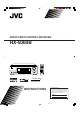
AUDIO/VIDEO CONTROL RECEIVER RX-5060B TA/NEWS/INFO DISPLAY MODE INSTRUCTIONS For Customer Use: Enter below the Model No. and Serial No. which are located either on the rear, bottom or side of the cabinet. Retain this information for future reference. Model No. Serial No. LVT1507-001A [J] Cover_RX-5060B[J].p65 3 05.11.
Warnings, Cautions and Others/ Mises en garde, précautions et indications diverses CAUTION RISK OF ELECTRIC SHOCK DO NOT OPEN CAUTION: TO REDUCE THE RISK OF ELECTRIC SHOCK. DO NOT REMOVE COVER (OR BACK) NO USER SERVICEABLE PARTS INSIDE. REFER SERVICING TO QUALIFIED SERVICE PERSONNEL.
Table of Contents Parts Identification ...................................... 2 Adjusting Sound ........................................ 21 Getting Started ........................................... 4 Basic Adjustment Items ............................................................ 21 Basic Procedure ........................................................................ 21 7 Adjusting the Equalization Patterns ..................................... 22 7 Adjusting the Speaker Output Levels ...........
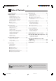
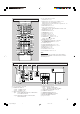
Parts Identification Front Panel 1 2 34 6 5 789p q MASTER VOLUME RX—6030V AUDIO/VIDEO CONTROL RECEIVER STANDBY DIMMER SURROUND STANDBY/ON INPUT DIGITAL DSP DUALMONO 3D - PHONIC VIRTUAL SB H.
See pages in parentheses for details.
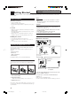
Getting Started Do not connect the AC power cord until all other connections have been made. This section explains how to connect audio/video components and speakers to the receiver, and how to connect the power supply. Notes: Before Installation General Precautions • Be sure your hands are dry. • Turn the power off to all components. • Read the manuals supplied with the components you are going to connect.
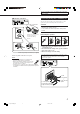
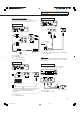
Do not connect the AC power cord until all other connections have been made. AM antenna connections Connecting the Speakers and Subwoofer You can connect five speakers (a pair of front speakers, a center speaker, and a pair of surround speakers) and a subwoofer. AM Loop Antenna (supplied) CAUTIONS: • Use only the speakers of the SPEAKER IMPEDANCE indicated by the speaker terminals. • Do not connect more than one speaker to each speaker terminal.
Do not connect the AC power cord until all other connections have been made. Getting Started Connecting the subwoofer Connecting Audio/Video Components You can enhance the bass by connecting a subwoofer. Connect the input jack of a powered subwoofer to the rear panel, using a cable with RCA pin plugs (not supplied). When connecting individual components, refer also to the manuals supplied with them. Analog Connections Audio component connections Use the cables with RCA pin plugs (not supplied).
Do not connect the AC power cord until all other connections have been made. Video component connections Use the cables with RCA pin plugs (not supplied). Connect the white plug to the audio left jack, the red plug to the audio right jack, and the yellow plug to the video jack.
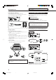
Do not connect the AC power cord until all other connections have been made. Getting Started Digital Connections Notes: By connecting the receiver and the source component through the digital terminals, sound reproduction quality will be much improved. In addition, you can enjoy multi-channel reproduction and some other convenient functions. IMPORTANT: • When connecting a video component using the digital terminals, you also need to connect it to the video jacks on the rear.
Basic Operations The following operations are commonly used when you play any sound sources. Operations hereafter will be explained using the buttons on the front panel. You can also use the buttons on the remote control for the same functions if they have the same and similar names/marks.
Basic Operations Speaker and signal indicators on the display By checking the following indicators, you can easily confirm which speakers you are activating and which signals are coming into this receiver. Speaker indicators Signal indicators Selecting different sources for picture and sound While watching pictures from a video source, you can listen to sound of an audio source.
Listening with headphones: Remote NOT You can enjoy not only stereo software but also multichannel software through the headphones. (Sounds are down-mixed to the front channels while playing multi-channel software.) Selecting the Analog or Digital Input Mode When you have connected digital source components using the both analog and digital terminals (see pages 6 to 8), you can select the input mode—either digital or analog—for these components. 1 Press SPEAKERS ON/OFF to deactivate the speakers.
Basic Operations When playing software encoded with Dolby Digital or DTS, the following symptoms may occur: • Sound does not come out at the beginning of playback. • Noise comes out while searching for or skipping chapters or tracks. In this case, press INPUT DIGITAL repeatedly to select “DOLBY DIGITAL” or “DTS SURROUND.
The following basic operations are possible only using the remote control. Recording a source You can record any sources playing through the receiver to a cassette deck (or a CD recorder) connected to the TAPE/CDR jacks and the VCR connected to the VCR jacks at the same time. While recording, you can listen to the selected sound source at whatever sound level you like without affecting the sound levels of the recording.
Receiving Radio Broadcasts You can browse through all the stations or use the preset function to go immediately to a particular station. Tuning in to Stations Manually Remote NOT 1 Press FM or AM to select the band. Using Preset Tuning Once a station is assigned to a channel number, the station can be quickly tuned in. You can preset up to 30 FM and 15 AM stations. AUTO MUTING VOLUME To store the preset stations Remote NOT Before you start, remember...
To tune in a preset station Selecting the FM Reception Mode On the front panel: 1 Press FM or AM to select the band. 2 Press FM/AM PRESET 5 or ∞ until you find the channel you want. • Pressing FM/AM PRESET 5 increases the number. • Pressing FM/AM PRESET ∞ decreases the number. When an FM stereo broadcast is hard to receive or noisy, you can change the FM reception mode while receiving an FM broadcast. • You can store the FM reception mode for each preset station (see page 14).
Basic Settings Some of the following settings are required after connecting and positioning your speakers while others will make operations easier. You can use QUICK SPEAKER SETUP to easily set up your speaker configuration. Quick Speaker Setup Remote NOT Quick Speaker Setup helps you to easily and quickly register the speaker size and speaker distance according to your listening room to create the best possible surround effect. • You can also register each speaker’s information manually.
Basic Setting Items Basic Procedure Remote NOT On the following pages, you can adjust the following items: • You can only select the items currently available. For details, see the explanation of each item. Items SUBWOOFER* To do See page Register your subwoofer. 18 FRNT SPEAKERS* Register your front speaker size. 18 CNTR SPEAKER* 18 Register your center speaker size. SURR SPEAKERS* Register your surround speaker size.
Basic Settings Setting the Speakers To obtain the best possible surround effect from the Surround and DSP modes, register the setting about the speaker arrangement after all connections are completed. • If you have used Quick Speaker Setup on page 16, this setting is not required. ¶ Subwoofer setting—SUBWOOFER Select whether you have connected a subwoofer or not.
¶ Crossover frequency—CROSSOVER You can select the crossover frequency for the small speakers used. The signals below the preset frequency level will be sent to and be reproduced by the subwoofer (or by “LARGE” speakers when “SUBWOOFER” is set to “SUBWOOFER NO”). Select one of the crossover frequency levels according to the size of the small speaker connected. CROSS 80HZ: Select when the cone speaker unit built in the speaker is about 12 cm (4 3/4 inches).
Basic Settings Setting for Effective Surround Operations ¶ Virtual Surround Back—VIRTUAL SBACK You can enjoy the surround back channel while playing back Dolby Digital Surround EX software or DTS-ES software without the surround back speakers. This function creates the great surround effect from the behind as if you have connected the surround back speakers. Select “VRTL SB ON” to activate Virtual Surround Back.
Adjusting Sound You can make sound adjustment to your preference after completing basic settings. Basic Adjustment Items Basic Procedure Remote NOT On the following pages, you can adjust the following items: • You can adjust only the items applicable to the current sound mode. Items To do See page DEQ 63HZ Adjust equalizer pattern at 63 Hz. 22 DEQ250HZ Adjust equalizer pattern at 250 Hz. 22 DEQ 1KHZ Adjust equalizer pattern at 1 kHz. 22 DEQ 4KHZ Adjust equalizer pattern at 4 kHz.
Adjusting Sound Adjusting the Equalization Patterns For Pro Logic II Music only You can adjust the equalization patterns to your preference. • Once you have made adjustment, it is memorized for each source. PANORAMA CTRL: Select “PANORAMA ON” to add “wraparound” sound effect with side-wall image. • To cancel it, select “PANORAMA OFF.
Using the Surround Modes This unit activates a variety of Surround modes automatically. The basic settings and adjustments stored (see pages 16 to 22) are applied automatically. Reproducing Theater Ambience Introducing the Surround Modes In a movie theater, many speakers are located on the walls to reproduce impressive multi-surround sounds, reaching you from all directions. With these many speakers, sound localization and sound movement can be expressed.
Using the Surround Modes DTS*2 DTS is another digital signal compression method, developed by Digital Theater Systems, Inc., and enables multi-channel encoding and decoding (1ch up to 6.1ch). • When DTS signal is detected through the digital input, the indicator lights up on the display. DTS Digital Surround DTS Digital Surround (DTS SURROUND) is another discrete 5.1-channel digital audio format available on CD, LD, and DVD software.
Activating the Surround Modes Available Surround modes vary depending on the incoming signals. • For DTS multi-channel digital software (except 2-channel and Dual Mono software), incoming signals are automatically detected and “DTS SURROUND” is activated. Activating one of the Surround modes for a source automatically recalls the memorized settings and adjustments (see pages 16 to 22).
Using the DSP Modes This unit activates a variety of DSP modes automatically. The basic settings and adjustments stored (see pages 16 to 22) are applied automatically. Reproducing the Sound Field The sound heard in a concert hall, club, etc. consists of direct sound and indirect sound—early reflections and reflections from behind. Direct sounds reach the listener directly without any reflection. On the other hand, indirect sounds are delayed by the distances of the ceiling and walls.
All Channel Stereo This mode can reproduce a larger stereo sound field using all the connected (and activated) speakers. • If the surround speakers are set to “NONE,” you cannot select “ALL CH STEREO.” Activating the DSP Modes Activating one of the DSP modes for a source automatically recalls the memorized settings and adjustments (see pages 16 to 22). Sound reproduced from normal stereo 1 Select and play any source. 2 Press DSP repeatedly until the DSP mode you want appears on the display.
COMPU LINK Remote Control System The COMPU LINK remote control system allows you to operate JVC’s audio components through the remote sensor on the receiver. To use this remote control system, you need to connect JVC’s audio components through the COMPU LINK (SYNCHRO) jacks using the cables with monaural mini-plugs (not supplied, see below) in addition to the connections using cables with RCA pin plugs (see page 6). • Make sure that the AC power cords of these components are unplugged before connection.
Operating JVC’s Audio/Video Components You can operate JVC’s audio and video components with this receiver’s remote control, since control signals for JVC’s components are preset in the remote control.
Operating JVC’s Audio/Video Components CD changer After pressing CD-DISC, you can perform the following operations on a CD changer: 3: 4: ¢: 7: 8: 1 – 6, 7/P: Start playing. Return to the beginning of the current (or previous) track. Skip to the beginning of the next track. Stop playing. Pause playing. To resume, press 3. Select the number of a disc installed in a CD changer. After pressing CD, you can perform the following operations on a CD changer: 1 – 10, +10: Select a track number directly.
Operating Other Manufacturers’ Video Equipment This remote control supplied for the receiver can transmit control signals for other manufacturers’ TVs, CATV converters, VCRs and DVD players. When operating the other manufacturers’ components, refer also to the manuals supplied with them. • After replacing batteries for the remote control, you need to set the manufactures’ codes again. To change the transmittable signals for operating another manufacturer’s TV 1 Set the TV/CATV selector to “TV.
Operating Other Manufacturers’ Video Equipment To change the transmittable signals for operating another manufacturer’s VCR To change the transmittable signals for operating another manufacturer’s DVD player 1 Press and hold STANDBY/ON 1 Press and hold STANDBY/ON VCR. DVD. 2 Press VCR. 2 Press DVD. 3 Enter a manufacturer’s code using buttons 1 – 9, and 0. 3 Enter a manufacturer’s code using buttons 1 – 9, and 0.
Troubleshooting Use this chart to help you solve daily operational problems. If there is any problem you cannot solve, contact your JVC’s service center. PROBLEM POSSIBLE CAUSE SOLUTION The display does not light up. The power cord is not plugged in. Plug the power cord into an AC outlet. No sound from speakers. Speaker signal cables are not connected. Check speaker wiring and reconnect if necessary. (See page 5.) The SPEAKERS ON/OFF button is not set correctly.
Specifications Amplifier Output Power Front channels: 100 W per channel, min. RMS, driven into 8 Ω, at 1 kHz with no more than 10% total harmonic distortion. Center channel: 100 W, min. RMS, driven into 8 Ω, at 1 kHz with no more than 10% total harmonic distortion. Surround channels: Audio Audio Input Sensitivity/Impedance (1 kHz) CD, TAPE/CDR, VCR, TV SOUND, DVD, AUX: Audio Input (DIGITAL IN)* Coaxial Optical DIGITAL 1 (DVD): DIGITAL 2 (CD): 100 W per channel, min.
FM tuner (IHF) Tuning Range: 87.5 MHz to 108.0 MHz Usable Sensitivity Monaural: 12.8 dBf (1.2 µV/75 Ω) 50 dB Quieting Sensitivity Monaural: Stereo: 16.0 dBf (1.7 µV/75 Ω) 37.5 dBf (20.5 µV/75 Ω) Stereo Separation at OUT (REC): AM tuner Tuning Range: 35 dB at 1 kHz 530 kHz to 1 710 kHz General Power Requirements: AC 120V , 60 Hz Power Consumption: 155 W/200 VA (at operation) 0.8 W (in standby mode) Dimensions (W x H x D): 435 mm x 146.5 mm x 369.5 mm (17 3/16 in. x 5 13/16 in. x 14 5/8 in.
Warr&CS_RX-5060B[J].p65 36 05.11.
Warr&CS_RX-5060B[J].p65 37 05.11.
RX-5060B AUDIO/VIDEO CONTROL RECEIVER EN © 2005 Victor Company of Japan, Limited Cover_RX-5060B[J].p65 2 1205YHMMDWJEIN 05.11.