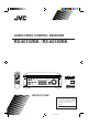
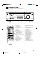
AUDIO/VIDEO CONTROL RECEIVER RX-6010VBK / RX-6018VBK POWER SLEEP TV SURROUND TEST VCR 2 EFFECT 3 – CENTER + 5 5 6 AUDIO/VIDEO CONTROL RECEIVER – REAR•L + 8 5 7/P TV/VIDEO 5 5 4 – VCR CH + SOUND AUDIO – SUBWOOFER + 1 SURROUND MODE CD-DISC 9 MENU FM/AM TUNING – REAR•R + 10 ENTER DVD TV SOUND CD TAPE/CDR FM/AM PRESET FM MODE +10 STANDBY VCR ANALOG/DIGITAL MASTER VOLUME MEMORY POWER FM/AM D I G I T A L SURROUND MUTING + + TV VOL VOLUME – 8 – 1 SURROUND ON/OFF
Warnings, Cautions and Others/ Mises en garde, précautions et indications diverses CAUTION RISK OF ELECTRIC SHOCK DO NOT OPEN CAUTION: TO REDUCE THE RISK OF ELECTRIC SHOCK. DO NOT REMOVE COVER (OR BACK) NO USER SERVICEABLE PARTS INSIDE. REFER SERVICING TO QUALIFIED SERVICE PERSONNEL.
For Canada/pour Le Canada THIS DIGITAL APPARATUS DOES NOT EXCEED THE CLASS B LIMITS FOR RADIO NOISE EMISSIONS FROM DIGITAL APPARATUS AS SET OUT IN THE INTERFERENCE-CAUSING EQUIPMENT STANDARD ENTITLED “DIGITAL APPARATUS,” ICES-003 OF THE DEPARTMENT OF COMMUNICATIONS.
Table of Contents Parts Identification ...................................... 2 Getting Started ........................................... 3 Before Installation ...................................................................... 3 Checking the Supplied Accessories ........................................... 3 Connecting the FM and AM Antennas ....................................... 3 Connecting the Speakers ............................................................
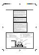
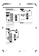
Parts Identification Become familiar with the buttons and controls on the receiver before use. Refer to the pages in parentheses for details.
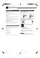
Getting Started This section explains how to connect audio/video components and speakers to the receiver, and how to connect the power supply. Before Installation General Connecting the FM and AM Antennas FM Antenna Connections • Be sure your hands are dry. • Turn the power off to all components. • Read the manuals supplied with the components you are going to connect.
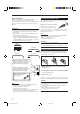
AM Antenna Connections Basic connecting procedure Snap the tabs on the loop into the slots of the base to assemble the AM loop. ANTENNA FM 75 COAXIAL AM LOOP AM Loop Antenna AM EXT 2 1 3 2 1 3 1 Cut, twist and remove the insulation at the end of each speaker signal cable (not supplied). 2 Open the terminal and then insert the speaker signal cable. 3 Close the terminal. Connecting the front speakers Connect front speakers to the FRONT SPEAKERS terminals.
Connecting the subwoofer speaker Cassette deck or CD recorder You can enhance the bass by connecting a subwoofer. Connect the input jack of a powered subwoofer to the SUBWOOFER OUT jack on the rear panel, using a cable with RCA pin plugs (not supplied).
Video component connections Use the cables with RCA pin plugs (not supplied). Connect the white plug to the audio left jack, the red plug to the audio right jack, and the yellow plug to the video jack.
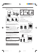
Connecting the Power Cord Digital connections This receiver is equipped with two DIGITAL IN terminals — one digital coaxial terminal and one digital optical terminal. You can connect any component to one of the digital terminals using a digital coaxial cable (not supplied) or digital optical cable (not supplied). IMPORTANT: • When connecting the DVD player or digital TV broadcast tuner using the digital terminal, you also need to connect it to the video jack on the rear.
Basic Operations The following operations are commonly used when you play any sound source. Turning the Power On and Off (Standby) Selected source name appears On the front panel: POWER Current source name appears L R VOLUME To turn off the power (into standby mode), press AUDIO in the POWER section again. The STANDBY lamp lights up. Selecting the Source to Play Press one of the source selecting buttons. On the front panel: INPUT ATT C R LS S POWER AUDIO RS Select the DVD player.
Selecting different sources for picture and sound You can watch picture from a video component while listening to sound from another component. Press one of the audio source selecting buttons (CD, TAPE/CDR, FM/AM), while viewing the picture from a video component such as the VCR or DVD player, etc. On the front panel: CD TAPE/CDR FM/AM Listening Only with Headphones You must turn off speakers when you listen with headphones. 1. Connect a pair of headphones to the PHONES jack on the front panel. 2.
Adjusting the Subwoofer Output Level SPK ANALOG L INPUT ATT R H.PHONE R H.PHONE You can adjust the subwoofer output level if you have selected “YES” for the “SUBWOOFER” (see page 11). Once it has been adjusted, the receiver memorizes the adjustment. Before you start, remember... • There is a time limit in doing the following steps. If the setting is canceled before you finish, start from step 1 again. • When the front speakers are deactivated, the subwoofer level cannot be adjusted.
Basic Settings Some of the following settings are required after connecting and positioning your speakers in your listening room, while others will make operations easier. Recording a Source Setting the Subwoofer Information You can record any source playing through the receiver to a cassette deck (or a CD recorder) connected to the TAPE/CDR jacks and the VCR connected to the VCR jacks at the same time.
Setting the Speakers for the DSP Modes To obtain the best possible surround sound of the DSP (Digital Signal Processor) modes (see page 18), you have to register the information about the speakers arrangement after all connections are completed. Before you start, remember... • There is a time limit in doing the following steps. If the setting is canceled before you finish, start from step 1 again.
Crossover Frequency Setting Low Frequency Effect Attenuator Setting Small speakers cannot reproduce the bass sound very well. So, if you have used a small speaker for any of the front, center, and rear channels, this receiver automatically reallocates the bass elements, originally assigned to the channel for which you have connected the small speaker, to another channel (for which you have connected the large speaker).
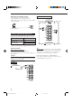
Digital Input (DIGITAL IN) Terminal Setting When you use the digital input terminals, you have to register what components are connected to which terminals (DIGITAL IN 1/2). Before you start, remember... • There is a time limit in doing the following steps. If the setting is canceled before you finish, start from step 1 again. On the front panel ONLY: T SETTING 1. Press SETTING repeatedly until “DIGITAL IN” appears on the display.
When playing a software encoded with the DTS Digital Surround, “AUTO” may not work properly and the following symptoms may occur: • Sound does not come out at the beginning of playback. • Noise comes out while using the searching or skipping function. In this case, press CONTROL UP 5/ DOWN ∞ to select “DTS” while “AUTO” is lit on the display.
Receiving Radio Broadcasts You can browse through all the stations or use the preset function to go immediately to a particular station. Tuning in Stations Manually 2. Press MEMORY. MEMORY On the front panel ONLY: 1. Press FM/AM to select the band (FM or AM). SPK FM/AM ANALOG L • Each time you press the button, the band alternates between FM and AM. L TUNED VOLUME CH- “CH-” appears and the channel number position starts flashing on the display for about 5 seconds. SPK ANALOG R R TUNED 2.
To tune in a preset station Selecting the FM Reception Mode On the front panel: 1. Press FM/AM to select the band (FM or AM). When an FM stereo broadcast is hard to receive or noisy FM/AM You can change the FM reception mode while receiving an FM broadcast. • You can store the FM reception mode for each preset station. • The last received station of the selected band is tuned in. On the front panel ONLY: SPK ANALOG L R TUNED VOLUME Press FM MODE. 2.
Using the DSP Modes The built-in Surround Processor provides two types of the DSP (Digital Signal Processor) mode — Surround mode and DAP (Digital Acoustic Processor) mode. What are the DSP Modes? Surround modes With this receiver, you can use three types of the Surround mode. Following modes cannot be used when only the front speakers are connected to this receiver (without the rear speakers or center speaker).
Reproducing the Sound Field DAP modes The sound heard in a concert hall or club consists of direct sound and indirect sound — early reflections and reflections from behind. Direct sounds reach the listener directly without any reflection. On the other hand, indirect sounds are delayed by the distances of the ceiling and walls. These direct sounds and indirect sounds are the most important elements of the acoustic surround effects.
Available DSP Modes According to the Speaker Arrangement Available DSP modes will vary depending on how many speakers are used with this receiver. Make sure that you have set the speaker information correctly (see page 12).
Adjusting the Surround Modes 5. Adjust the speaker output levels. Once you have adjusted the Surround modes, the adjustment is memorized for each Surround mode. Dolby and DTS Surround adjustments Before you start, remember... • Make sure that you have set the speaker information correctly (see page 12). • There is a time limit in doing the following steps. If the setting is canceled before you finish, start from step 3 again.
JVC Theater Surround adjustments Before you start, remember... • Make sure that you have set the speaker information correctly (see page 12). • There is a time limit in doing the following steps. If the setting is canceled before you finish, start from step 2 again. • You cannot adjust the rear speaker output levels when you have set “REAR SPK” to “NO.” See page 12. • You cannot adjust the center speaker output level when you have set “CENTER SPK” to “NO.” See page 12. From the remote control: EFFECT 6.
From the remote control: Adjusting the DAP Modes Once you have adjusted the DAP modes, the adjustment is memorized for each DAP mode. Before you start, remember... • Make sure that you have set the speaker information correctly (see page 12). • There is a time limit in doing the following steps. If the setting is canceled before you finish, start from step 1 again. • You cannot adjust the rear speaker output level when you have set “REAR SPK” to “NO.” See page 12.
Activating the DSP Modes For the other DSP modes You can use only one DSP mode at a time. When a DSP mode is activated, another DSP mode is canceled if in use. For Dolby Pro Logic, Dolby Digital, and DTS Digital Surround On the front panel: 1. Press DSP MODE repeatedly until the mode you want appears on the display. DSP MODE • Each time you press the button, the DSP modes change. (See page 20 for more details.) On the front panel: 1. Press SURROUND ON/OFF.
COMPU LINK Remote Control System The COMPU LINK remote control system allows you to operate JVC audio components through the remote sensor on the receiver. To use this remote control system, you need to connect JVC audio components through the COMPU LINK (SYNCHRO) jacks (see below) in addition to the connections using cables with RCA pin plugs (see page 5). • Make sure that the AC power cords of these components are unplugged before connection.
Operating JVC’s Audio/Video Components You can operate JVC’s audio and video components with this receiver’s remote control, since control signals for JVC components are preset in the remote control.
3: 4: ¢: 7: 8: 1 – 6, 7/P: Starts playing. Returns to the beginning of the current (or previous) track. Skips to the beginning of the next track. Stops playing. Pauses playing. To release it, press 3 . Selects the number of a disc installed in a CD changer. If your CD changer is of 200-disc loading capability (except for XL-MC100 and XL-MC301), you can do the following operations using the number buttons after pressing CD. • The 10 button can function as 0. 1. Select a disc number. 2.
Troubleshooting Use this chart to help you solve daily operational problems. If there is any problem you cannot solve, contact your JVC service center. PROBLEM POSSIBLE CAUSE SOLUTION The display does not light up. The power cord is not plugged in. Plug the power cord into an AC outlet. No sound from speakers. Speaker signal cables are not connected. Check speaker wiring and reconnect if necessary. The SPEAKERS ON/OFF button is not set correctly. Press SPEAKERS ON/OFF button correctly.
Specifications Amplifier Output Power At Stereo operation: Front channels: 100 W per channel, min. RMS, driven into 8 Ω, 40 Hz to 20 kHz with no more than 0.8% total harmonic distortion. At Surround operation: Audio Audio Input Sensitivity/Impedance (1 kHz): Audio Input (DIGITAL IN)* : Audio Output Level: Signal-to-Noise Ratio (’66 IHF/’78 IHF): Frequency Response (8 Ω): Tone Control: Front channels: 100 W per channel, min. RMS, driven into 8 Ω at 1 kHz with no more than 0.
FM tuner (IHF) Tuning Range: 87.5 MHz to 108.0 MHz Usable Sensitivity: Monaural: 12.8 dBf (1.2 µV/75 Ω) 50 dB Quieting Sensitivity: Monaural: Stereo: 21.3 dBf (3.2 µV/75 Ω) 41.3 dBf (31.5 µV/75 Ω) Signal-to-Noise Ratio (IHF-A weighted): Monaural: Stereo: 78 dB at 85 dBf 73 dB at 85 dBf Total Harmonic Distortion: Monaural: Stereo: 0.4% at 1 kHz 0.6% at 1 kHz Stereo Separation at REC OUT: Alternate Channel Selectivity: Frequency Response: 35 dB at 1 kHz 45 dB: (±400 kHz) 30 Hz to 15 kHz: (+0.
QUALITY SERVICE HOW TO LOCATE YOUR JVC SERVICE CENTER TOLL FREE : 1-800-537-5722 http://www.jvcservice.com Dear customer: In order to receive the most satisfaction from your purchase, read the instruction booklet before operating the unit. In the event that repair is necessary, or for the address nearest your location, please refer to the factory service center list below or within the Continental United States, Call 1-800-537-5722 for your authorized servicer.
LIMITED WARRANTY AUDIO-2 JVC COMPANY OF AMERICA warrants this product and all parts thereof, except as set forth below ONLY TO THE ORIGINAL PURCHASER AT RETAIL to be FREE FROM DEFECTIVE MATERIAL AND WORKMANSHIP from the date of original retail purchase for the period as shown below. (“The Warranty Period.”) PARTS LABOR 2YR 2YR THIS LIMITED WARRANTY IS VALID ONLY IN THE FIFTY(50) UNITED STATES, THE DISTRICT OF COLUMBIA AND IN COMMONWEALTH OF PUERTO RICO.
VICTOR COMPANY OF JAPAN, LIMITED V EN RX-6010&6018V[J]COVER_f J 2 00.12.