JVC AU O/VIDEO CONTROL REC RX-6010VB K / RX-6018VB K Pl_dlll_l Jvn It I I IAIIf lt¥1Vlr v klllUl IIIIRemote /lll D i (; I T A L SURROUND DIGITAL INSTRUCTIONS For Customer Use: Enter below the Model No. and Serial No. which are located either on the rear, bottom or side of the cabinet. Retain this information for future reference. Model No. Serial No.
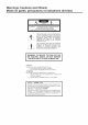
Warnings, Cautions and Others/ Mises en garde, precautions et indications diverses CAUTION: TO REDUCE THE RiSK OF ELECTRIC SHOCK. DO NOT REMOVE COVER (OR BACK) NO USER SERVICEABLE PARTS INSIDE. SERVICING TO QUALIFIED SERVICE PERSONNEL.
For Canada/pour Le Canada THIS DIGITAL APPARATUS DOES NOT EXCEED THE CLASS B LIMITS FOR RADIO NOISE EMISSIONS FROM DIGITAL APPARATUS AS SET OUT IN THE INTERFERENCE-CAUSING EQUIPMENT STANDARD ENTITLED "DIGITAL APPARATUS," ICES-003 OF THE DEPARTMENT OF COMMUNICATIONS.
of Contents Parts identification Getting Started ...................................... 2 ........................................... 3 Be_i_re Installation ................................................................. 3 Checking the Supplied Accessories ......................... Connecting the FM and AM Antennas ....................................... 3 3 4 . > 7 Connecting the Speakers ............................................................ Connecting Audio/Video Components ..........
Parts Become Refer familiar Identification with to the pages the buttons in parentheses and controls on the receiver before use. for details. AUD_OIWD _ CONTROL RECEIVER i ME_Y I I Remote Control i ] POWER JVC buttons TV.
Getting This section power explains how Started to connect audio/video components and speakers to the receiver, General • Turn the power to connect the are dry. aftra • Read the manuals connect. all components. supplied with the components you are going to Locations • Install the receiver moisture.
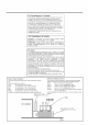
AM Antenna Connections Basic connecting procedure 2 3 Snap the tabs on the loop into the slots of the base to assemble the _ANTENRA_ FN 75Q COAXIAL AM loop. Cut, twist and remove each speaker signal cable Open the terminal signal cable. 2 the insulation at the end of (not supplied). and then insert the speaker Close the terminal. Connecting the front; speakers Connect fi'ont speakers to the FRONT SPEAKERS terminals.
Connecting the You can enhance the bass by connecting Connect the input jack of a powered SUBWOOFER speaker subwasfeP I Cassettedeckor CDrecorder I a subwoofzr. subwoofzr OUT jack on the rear panel, to the Cassette using a cable with RCA pin plugs (not supplied). deck To audio To audio input output m SUBW00FER Powered subwoofer IN (PLAY) You can connect the following audio video components to this receiver. Ref)r also to the manuals supplied with your components.
Video component connections I DVD player I Use the cables with RCA pin plugs (not supplied). Connect the white plug to the audio lef_tiack, the red plug to the audio right jack, and the yellow plug to the video .iack.
Digital connections This receiver is equipped with two DIGITAL IN terminals one digital coaxial terminal and one digital optical terminah You can connect any component to one of the digital terminals using a digital coaxial cable (not supplied) or digital optical cable (not supplied). iMPORTANT: • When connecting the DVD player or digital TV broadcast tuner using the digital terminal, you also need to connect it to the video jack on the rear.
Basic Operations The following operations o - are commonly " , - 0 . _ used when 0 . you play any sound source. o p Selected On the front panel: source name SPK _LFE i cH- POWER appears DVD Select the DVD player. Select the TV sonnd. TV SOUND / VCR T, I/ £! T, V "-'i 1-- -L! 'Z: volume level is shown here Select the video component _1 CD * ...... o_ TAPE/CDR FM/AM To turn off the power press POWER of power "_ to the Select the CD player.
Selecting different sources You can watch picture sound fi'om another selecting picture etc. buttons for picture fi'om a video component. component FMiAM), sound while listening Press one of the audio (CD, TAPEiCDR, fi'om a video component and to You must turn off speakers source while viewing when you listen with headphones. the such as the VCR or DVD player, 1. Connect a pair ofhea@hones to the PHONES jack on the fi'ont panel. 2.
SPK ANALOa D[21_ You can adjust "YES" Once the subwoof)r output fbr the "SUBWOOFER" it has been adjusted, Before you start, • When the receiver On memorizes be_bre you finish, frong I I__1! _l ! steps. If the setting are deactivated, H_*a,E " _ Y""=" _.lql the subwoof)r level panel: "SUBWFR the displaj: ANALOG rcl_N is start fi'om step 1 again. 'T ] ,,,,-,,:-:,Me,, I_.I ! I q i_.ii _ lit_. Notes: 1. Press ADJUST The display ! the adjustment. be adjusted.
Basic Settings Some of the od_ers following will make You can record setdngs operations are required any source playing deck (or a CD recorder) VCR connected after connecting and positioning your connected through the receiver to a cassette to the TAPE CDR jacks Register you haxe connected _xhether Before you start, • There whatever you can listen to the selected sound level you like without sound affecting source at the sound On the befbre front panel The display 2.
- _ - a - . - 0 _ [_ m e 0 Deiay Time Setting Center - Register To obtain the best possible Signal Processor) infbnnation modes surround sound (see page about the speakers of the DSP (Digital 18), you have to register arrangement comparing the are fi'om your listening • There is a time limit in doing the fbllowing you finish, Center, and steps. If the setting is • When Rear Speaker Setting 1. Register the sizes of all the connected speakers.
Crossover Frequency Setting Low Small speakers cannot reproduce the bass sound very well. So, if" you have used a small speaker fbr aW of the front, center, and rear channels, this receiver automatically reallocates the bass elements, originally assigned to the channel for which you have connected the small speaker, to another channel (lbr which you have connected the large speaker). If you have selected "LARGE" for all speakers (see page 12), this fhnction will not take ef[ect.
- When When you use the digital components Before are connected you start, input terminals, to which you have to register terminals (DIGITAL On the betbre frong you finish, - 1 . you have connected analog connection _ o o digital _ source o . g components (see page 5) and the digital _ o - using both the connection (see page 7), you need to select the input mode IN 12). panel steps. If the setting changes is start fi'om step 1 again. OILILY: SETTING 1.
When playing Surround, a software "AUTO" symptoms encoded with the DTS Digital may not work properly and the fbllowing may occur: • Sound does not come out at the beginning • Noise comes function. out while using the searching of playback. or skipping You can assign and store different playing By using this function, source. the settings every, time you change for the newly In this case, press CONTROL DOWN V to select "DTS" is lit on the display.
I Receiving You can browse d_rough Radie all d_e stadons Broadcasts or use the preset funcdon to go immediately to a particular stadon. 2. Press MEMORY. On the front 1. Press panel FM/AM MEMORY % ONLY: to select the band VOLUME (FM or AM). • Each time you press the button, the band alternates between FM and AM. t_J i, 4_I h I 4ii LJ I 7/ ..... ._! I-_1 "CH-" appears and the channel number position starts flashing on the display for about 5 seconds.
To tune in a preset On the front 1. Press station panel: FM/AM to select When an FM stereo the band hroadcasB (FM or AM). • The last received station of the selected band is tuned in. You can change broadcast. the FM reception • You can store the FM reception _oG [_ [] mw_o t-'-'L:! !.
Using the DSP Modes The built-in Surround Processor provides two types of the DSP [Digital Signal Processor] mode -- Surround mode and DAP [Digital Acousdc Processor] mode. DTS SuPPound modes With this receiver, you can use three types of the Sun'ound Folio'wing cannot modes are connected center Digital Surroun# be used to this receiver when only the front (without the rear Compared mode.
DAP modes = The sound heard and indirect Direct sound sounds early reflections indirect sounds and _x_alls. These most important mode hall or club consists reach the listener the other hand, ceiling in a concert direct elements there" speakers feeling. directly speaker You can select LIVE sounds surround to this receiver On Direct € s - effects. sounds ceiling The DAP e - e s and walls.
Available DSP modes will vary depending on how many speakers are used with this receix er. Make sure that you have set the speaker information correctly (see page 12).
5. Adjust the speaker • To adjust Once you have adjusted the Sun'ound memorized for each Surround mode. Dolb V and DTS Surround Before you start, • Make the adjustment you have set the speaker information + before • You cannot you finish, levels. -eENT_a÷ level, press (from +10 dB to 10 dB). • To adjust REAR.L the lef' rear speaker lexel, press +/ (fi'om +10 dB to l0 dB). • To adjust REAR.R the right rear speaker +M (fi'om +10 dB to %/ -R_aR.C* level, press 10 dB).
JVC Theater 6. Press EFFECT adjustmente Surround sure that (see page you have set the speaker information betbre • You cannot you finish, SPK" to "NO." See page adjust the center set "(?ENTER the SPK" remote steps. If the setting output is output As the number increases, JVC Theater Surround becomes stronger (normally set it to "DSP EFFECT 3"). level when you have See page 12.
_ e - o _ j X m From o o- 1. Once you have adjusted the DAP modes, memorized fbr each DAP mode. the adjustment is the pemot;e Press Before you start, • Make (see page you have set the speaker information canceled betbre • You cannot "REAR you finish, steps. If the setting MODE the DANCE adjust the rear speaker is output The DSP indicator 2. Adjust 1) SouND the following appears 3. Adjust the rear speaker "%/ also lights up on the display.
. e - NO m o o For the ocher DSP modes - You can use only one DSP mode at a time. When a DSP mode actix ated, another DSP mode is canceled if in use. For Ooibv Pro Logic, Digital Surround Ooib V Digital, and is On the front panel: 1. Press DSP MODE repeatedly until the mode you want appears on the display. D'I_ • Each time yon press the button, modes change. details.) On the front panel: 1.
COMPU The COMPU d_e receiven LINK To use this remote components below) remote control through in addition LINK Remete control system, the COMPU system allows you to operate you need to connect JVC audio LINK acks (see to the connections (SYNCHRO)j befbre all connections Automatic with the components Power COMPU Both the CD player sure that the AC power unplugged JVC audio connection. cords of these components are off (standby) Plug the AC power cords only after are complete.
Operating You can operate components JVC'S audio are preset in the and JVC's Audio/Video Components video control, remote components with this receiver's remote since control signals for JVC control. Tuner After IMPORTANT: To operate JVC's audio components using this remote control: • You need to connect JVC audio components through the COMPU LINK (SYNCHRO)jacks (see page 25) in addition to the connections using cables with RCA pin plugs (see page 5).
CD chang_E Af'er pressing CD-DISC, you can perfonn the following operations on a CD changer: m,-: I.,_q: Starts playing. Returns to the beginning of the current (or previous) track. Skips to the beginning of the next track. Stops playing. Pauses playing. To release it, press |_. Selects the nmnber of a disc installed in a CD changer.
Troubleshooting Use this chart to help you so/re daily operadona/ prob/ems. /f there POSSIBLE CAUSE is any prob/em you cannot so/re, contact your JVC sePvice cen[en PROBLEM SOLUTION The display does not light up. The poxxer cord is not plugged No sound from speakers. Speaker signal cables are not colmected. Check speaker wiring and recolmect necessary. The SPEAKERS ON/OFF button is not set correctly. Press SPEAKERS ON/OFF button correctly. An incorrect source is selected.
Specifications Amplifier Output Power At Stereo operation: Front channels: At Surround 100 W per channel, rain. RMS, driven into 8 f_, 40 Hz to 20 kHz with no more than 0.8% total harmonic distortion. operation: Front channels: 100 W per channel, rain. RMS, driven into 8 f_ at 1 lcHz with no more than 0.8% total harmonic distortion. Center 100 W_ min. RMS, driven into 8 f_ at 1 kHz, with no more than 0.8% total harmonic distortion. channel: Rear channels: 100 W per channel, rain.
FM tuner {IHF) Tuning Range: 87.5 MHz to 108.0 MHz Usable Sensitivity: Monaural: 12.8 dBf (1.2 uVi75 f_) 50 dB Quieting Sensitivity: Monaural: 21.3 dBf (3.2 uVi75 f_) Stereo: 41.3 dBf(31.5 Monaural: 78 dB at 85 dBf Stereo: 73 dB at 85 dBf Monaural: 0.4% at 1 kHz Stereo: 0.
QUALITY SERVICE HOW TO LOCATE YOUR JVC SERVICE TOLL FREE CENTER : 1-800-537-5722 http://www.jvcservice.com Dear customer: In order to receive the most satisfaction from your purchase, read the instruction booklet before operating the unit. In the event that repair is necessary, or for the address nearest your location, please refer to the factory service center list below or within the Continental United States, Carl 1-800-537-5722 for your authorized servicer.
ltr LIMITED WARRANTY AUDIO-2 JVC COMPANY OF AMERICA warrants this product and atl parts thereof, except as set forth below ONLY TO THE ORIGINAL PURCHASER AT RETAIL to be FREE FROM DEFECTIVE MATERIAL AND WORKMANSHIP from the date of original retail purchase for the period as shown below, ("The Warranty Period.") PARTS LABOR 2YR THIS LIMITED WARRANTY IS VALID ONLY IN THE FIFTY(50) COMMONWEALTH OF PUERTO RICO.
VICTOR E. COMPANY OF JAPAN. LIMITED _O_ OlOl.