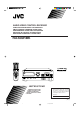
AUDIO/VIDEO CONTROL RECEIVER AUDIO/VIDEO-RECEIVER MIT STEUEREINHEIT AMPLI/TUNER DE COMMANDE AUDIO/VIDEO GEINTEGREERDE AUDIO/VIDEO-VERSTERKER RECEPTOR DE CONTROL DE AUDIO/VÍDEO RICEVITORE DI CONTROLLO AUDIO/VIDEO RX-630RBK /I SLEEP TV VCR AUDIO SEA MODE ONE TOUCH OPERATION CD-DISC 1 2 3 4 5 6 7/P 8 9 +10 0 10 CENTER ON/OFF TV VOLUME REAR CH MODE DELAY VCR TV SOUN VIDEO RX-630R D FM/AM TEST MASTER VOLUME AUDIO/VIDEO CONTROL RECEIVER VIDEO ONE TOUCH OPERATION CD TAPE – V
Warnings, Cautions and Others/Warnung, Achtung und sonstige Hinweise/ Mises en garde, précautions et indications diverses/Waarschuwingen, voorzorgen en andere mededelingen/Avisos, precauciones y otras notas/ Avvertenze e precauzioni da osservare IMPORTANT for the U.K. DO NOT cut off the mains plug from this equipment.
English ACHTUNG Zur Verhinderung von elektrischen Schlägen, Brandgefahr, usw: 1. Keine Schrauben lösen oder Abdeckungen enternen und nicht das Gehäuse öffnen. 2. Dieses Gerät weder Regen noch Feuchtigkeit aussetzen. PRECAUCIÓN Para reducir riesgos de choques eléctricos, incendio, etc.: 1. No extraiga los tornillos, los cubiertas ni la caja. 2. No exponga este aparato a la lluvia o a la humedad. ATTENTION Afin d’éviter tout risque d’électrocution, d’incendie, etc.: 1.
Caution –– POWER switch and STANDBY/ON button! POWER switch to be able to This apparatus is provided with a minimize power consumption for safe use. Therefore, 1. When doing initial setting, complete all the connections required, connect the mains plug into the wall outlet, and set the POWER switch to ON. After these, it will be available to operate STANDBY/ ON button and so on. 2. When not in use, set the POWER switch to OFF. 3. Disconnect the mains plug to shut the power off completely.
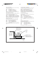
Caution: Proper Ventilation To avoide risk of electric shock and fire and to protect from damage. Locate the apparatus as follows: Front: No obstructions open spacing. Sides: No obstructions in 10 cm from the sides. Top: No obstructions in 10 cm from the top. Back: No obstructions in 15 cm from the back Bottom: No obstructions, place on the level surface. In addition, maintain the best possible air circulation as illustrated.
English Table of Contents Getting Started ........................................................................................................................... 2 Before Installation .................................................................................................................... 2 Checking the Supplied Accessories ......................................................................................... 2 Switches, Buttons and Controls ...............................................
This section explains how to connect audio/video components and speakers to the receiver, and how to connect the power supply. Before Installation General • Be sure your hands are dry. • Turn the power off to all components. • Read the manuals supplied with the components you are going to connect. Locations • Install the receiver in a location that is level and protected from moisture. • The temperature around the receiver must be between –5˚ and 35˚ C (23˚ and 95˚ F).
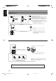
English Switches, Buttons and Controls Become familiar with the main switches and controls on your receiver before use.
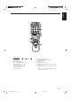
English Remote Control d /I f SLEEP TV VCR AUDIO g SEA MODE ONE TOUCH OPERATION h j 1 2 3 4 5 6 7/P 8 9 +10 0 10 CENTER k CD-DISC TV VOLUME REAR CH c v b n SURROUND CONTROL ON/OFF m MODE DELAY VCR T SOUV ND VIDEO l FM/AM CD TAPE / z x TEST PHO NO TE MU VOLUME + – PTY+ DISPLAY PTY MODE PTY– SEARCH , RM-SR630RU REMOTE CONTROL Remote Control , VCR , AUDIO d Power buttons (TV (12, 37) f SLEEP button (16) g SEA MODE button (26) h TV VOLUME buttons (+/–) (37) j C
English Connecting the FM and AM (MW/LW) Antennas FM Antenna Connections A A B NA EN T AN AN CO A NN TE 75 FMAXIAL 75 FMAXIAL CO B D D GN GN AM T EX AMP O LO AMP O LO AM T EX Using the Supplied FM Antenna The FM antenna provided can be connected to the FM 75ohm COAXIAL terminal as temporary measure. Using the Standard Type Connector (Not Supplied) A standard type connector (IEC or DIN45325) should be connected to the FM 75-ohm COAXIAL terminal.
English Connecting the Speakers You can connect the following speakers: • Two pairs of front speakers to produce normal stereo sound. • One pair of rear speakers to enjoy the surround effect. • One center speaker to produce more effective surround effect (to emphasize human voices). • One subwoofer to enhance the bass. For each speaker (except for subwoofer), connect the black (–) and red (+) terminals on the rear panel to the black (–) and red (+) terminals marked on the speakers.
English Connecting the rear and center speakers Cut, twist and remove the insulation at the end of each speaker signal cable first, and then, connect rear speakers to the REAR SPEAKERS terminals and a center speaker to the CENTER SPEAKER terminals by using the cables. CENTER SPEAKER 1 Open the terminal and then insert the speaker signal cable. 2 Close the terminal.
English About the speaker impedance of the speakers CAUTION: Use speakers with the SPEAKER IMPEDANCE indicated by the speaker terminals. Notes: • The required speaker impedance of the front speakers does not differ depending on whether both the FRONT SPEAKERS 1 and FRONT SPEAKERS 2 terminals are used or only one of them is used. • The required speaker impedance of the front speakers differs depending on whether or not a center and/ or rear speakers are connected at the same time.
English Connecting Audio/Video Components You can connect the following audio/video components to this receiver using cables with RCA pin plugs (not supplied). Refer also to the manuals supplied with your components. If you want to connect a component not listed in the table below, refer to the manual supplied with it.
GND English Video component connections AUDIO RIGHT LEFT PHONO To video input To audio input CD VIDEO VHS To audio output OUT (REC) VCR VCR To video output To audio output Video disc player IN (PLAY) VIDEO To video output OUT (REC) VCR TV SOUND IN (PLAY) VIDEO To video input MONITOR OUT To audio output TV OUT (REC) TAPE IN (PLAY) Connecting the Power Cord Before plugging the receiver into an AC outlet, make sure that all connections have been made. 1.
English Putting Batteries in the Remote Control Before using the remote control, put two supplied batteries first. When using the remote control, aim the remote control directly at the remote sensor on the receiver. 1. On the back of the remote control, remove the cover as illustrated. 2. Insert batteries. Make sure to observe the proper polarity: (+) to (+) and (–) to (–). 3. Replace the cover in.
English Basic Operations The following operations are commonly used when you play any sound source. Turning the Power On and Off On the front panel: . To turn on the power, press STANDBY/ON The STANDBY lamp goes off. The name of the current source (or station frequency) appears on the display. STANDBY STANDBY/ON Current source name appears Volume level is also shown here whenever the power is on.
English From the remote control: VCR T SOUV ND VIDEO FM/AM CD TAPE TEST PHO NO TE MU Press one of the source selecting buttons you want. VIDEO Play back a video source on the video component connected to the VIDEO jacks. VCR Play back a video source on the video component connected to the VCR jacks. TV SOUND Listen to TV sounds. FM/AM* Listen to the radio. TAPE* Listen to a cassette tape. CD* Listen to a CD. PHONO* Listen to a record.
A standard pair of headphones can be connected to the PHONES jack on the front panel. To listen with only headphones, press both SPEAKERS 1 and 2 to set them in the —OFF position. No sound comes out of the front speakers. CAUTION: Be sure to turn down the volume before connecting or putting on headphones, as high volume can damage both the headphones and your hearing.
English Basic Settings Some of the following settings are required after connecting and positioning your speakers in your listening room, while others will make operations easier. Adjusting the Front Speaker Output Balance If the sounds you hear from the front right and left speakers are unequal, you can adjust the speaker output balance. On the front panel only: SETTING 1. Press SETTING so that the Control % / fi / @ / # buttons work for adjusting the balance. The lamp next to the button lights up. 2.
Using the Sleep Timer, you can fall asleep to music and know the receiver will turn off by itself rather than play all night. SETTING On the front panel: 1. Press SETTING so that the Control % / fi / @ / # buttons work for setting the Sleep Timer. The lamp next to the button lights up. 2. Press Control % / fi until “” appears on the display. 3. Press Control @ / # to set the shut-off time.
English Selecting the Center Speaker Size You can register the information on the center speaker after all connections are completed. If you do this registration first, you do not have to adjust the center speaker mode when you want to activate the Dolby surround. However, to register the information, first you have to set the surround mode either to “PROLOGIC” or “3CHLOGIC.” (You cannot select the center speaker size when the surround mode is “SURR OFF” or “HALL.
English One Touch Operation This receiver can memorize the optimum sound settings for each playing source. About the One Touch Operation JVC’s One Touch Operation function is used to assign and store different sound settings for each different playing source. By using this function, you don’t have to change the settings every time you change the source. The stored settings for the newly selected source are automatically recalled.
English Receiving Radio Broadcasts You can browse through all the stations or use the preset function to go immediately to a particular station. Tuning in Stations Manually On the front panel only: TUNER 1. Press TUNER so that the Control % / fi / @ / # buttons work for tuner settings. The lamp next to the button lights up. MEMORY 2. Press Control % / fi until “” appears on the display. 3. Press Control @ / # to select the band.
English CAUTION: The preset channels may be erased in the following cases: • When you press POWER to set it in the —OFF position. • When you unplug the power cord. • When a power failure occurs. Tuning in a preset station On the front panel: TUNER 1. Press TUNER so that the Control % / fi / @ / # buttons work for tuner settings. The lamp next to the button lights up. MEMORY 2. Press Control % / fi until “–PRESET+” appears on the display. 3. Press Control @ / # to select a preset channel.
English Assigning Names to Preset Stations You can assign a name of up to five characters to each preset station (from preset channel number 1 to 20). When a preset station is tuned in, its assigned name will appear on the display. On the front panel only: 1. Tune in a preset station (preset channel number 1 to 20). See page 20 for details. TUNER 2. Press MEMORY (next to the TUNER button). The preset channel number starts flashing.
RDS allows FM stations to send an additional signal along with their regular program signals. For example, the stations send their station names, as well as information about what type of program they broadcast, such as sports or music, etc. When tuned to an FM station which provides the RDS service, the RDS indicator lights up on the display. With the receiver, you can receive the following types of RDS signals.
English FM/AM PTY+ \ DISPLAY PTY MODE PTY– SEARCH When pressing DISPLAY MODE on the remote control: Make sure that you have selected FM station using the remote control only. If not, the DISPLAY MODE button does not work for tuner operation. (Pressing FM/AM activates the remote control for tuner operation.) Notes: • If searching finishes at once, “PS”, “PTY”, and “RT” will not appear on the display.
PTY+ DISPLAY PTY MODE PTY– SEARCH 2. Press PTY +/– until the PTY code you want appears on the display. The display gives you the PTY codes described below. PTY+ DISPLAY PTY MODE PTY– SEARCH 3. Press PTY SEARCH again. While searching, “SEARCH” and the selected PTY code alternate on the display. The receiver searches 40 preset channels, stops when it finds the one you have selected, and tunes in that station.
English Switching to a Broadcast Program of Your Choice Temporarily Another convenient RDS service is called “EON (Enhanced Other Network).” This allows the receiver to switch temporarily to a broadcast program of your choice (NEWS, TA, and/or INFO) from a different station except in the following cases: • When you are listening to a non-RDS stations (all AM (MW/LW) and some FM stations). • When the last received FM station is a non-RDS station. On the front panel only: EON 1.
English Using the SEA Modes The SEA (Sound Effect Amplifier) modes give you control of the way your music sounds. Note: The SEA modes cannot be used for recording. Selecting Your Favorite SEA Mode On the front panel: 1. Press SEA MODE so that the Control % / fi buttons work for selecting the SEA mode. The lamp next to the button lights up. SEA MODE 2. Press Control % / fi until the mode you want appears on the display.
English Creating Your Own SEA Mode You can adjust and store your own SEA adjustment into memory (USERMODE). On the front panel only: If you do not want to store your adjustment, but rather want to adjust the SEA temporarily, skip step 3 below. SEA ADJUST 1. Press SEA ADJUST so that the Control % / fi / @ / # buttons work for the SEA adjustment. The lamp next to the button lights up. MEMORY 2. Adjust the SEA frequency and its level. • Press Control @ / # to select the frequency range to adjust.
The built-in surround processor provides three types of surround programs — Dolby Pro Logic, Dolby 3Channel Logic, and JVC’s Hall Surround. What is surround? The sound heard in a concert hall or a movie theater consists of direct sound and indirect sound: early reflections and reflections from behind. The reflected sounds are always delayed by the distances of the ceiling and walls from the listener. These reflections are some of the most important elements of the acoustic surround.
English 3. Press SURROUND ADJUST so that the Control % / fi / @ / # buttons work for surround settings. The lamp next to the button lights up. SURROUND ADJUST 4. Press Control % / fi until “– REAR +” appears on the display. 5. Press Control @ / # to adjust the rear speaker output level. • Pressing Control @ decreases the output level up to –10 dB. • Pressing Control # increases the output level up to +10 dB. 6. Press Control % / fi until “–DELAY +” appears on the display. 7.
The following illustrations show how to obtain the optimum sound environment for various Dolby Surround settings. Try to find the speaker direction and location to create the optimum sound field. CASE 1 When you have added a center speaker and rear speakers Front speaker TV Center speaker Rear speaker Front speaker Rear speaker In this case: 1.Select “PROLOGIC.” 2.Select “NORMAL” or “WIDE” for center mode. See pages 31 to 33 for more details.
English Preparing for Dolby Surround The receiver memorizes two sets of Dolby Surround adjustments; one for Pro Logic and the other for 3ch Logic. On the front panel: 1. Press SURROUND MODE so that the Control % / fi buttons work for selecting the surround modes. The lamp next to the button lights up. SURROUND MODE 2. Press Control % / fi until “PROLOGIC” or “3CHLOGIC” whichever you want appears on the display. The PRO LOGIC or 3CH LOGIC indicator (as well as the SURROUND indicator) also lights up.
English 6. Press Control % / fi until “–DELAY +” appears on the display. 7. Press Control @ / # to adjust the delay time of the rear speaker output. Each time you press the button, the delay time changes as follows: DELAY 1 DELAY 2 DELAY 4 DELAY 3 DELAY 1: Select this when the distance from you to your rear speakers is greater than that to the front speakers. DELAY 2: Select this when the distance from you to your rear speakers is almost equal to that to the front speakers.
English From the remote control: Note: You cannot adjust the center mode and the center tone using the remote control. 1. Press ON/OFF so that the SURROUND indicator lights up on the display. The previous surround mode is recalled (at its previous settings) and is shown on the display. Each time you press the button, the surround mode turns on and off. ON/OFF 2. Press MODE until “PROLOGIC” or “3CHLOGIC” whichever you want appears on the display.
Once you have set the Dolby Surround adjustments, you can use the same adjustment every time you want to enjoy Dolby Surround. The receiver memorizes two sets of Dolby Surround adjustment; one for Pro Logic and the other for 3ch Logic. On the front panel: 1. Press SURROUND MODE so that the Control % / fi buttons work for selecting the surround modes. The lamp next to the button lights up. SURROUND MODE 2. Press Control % / fi until “PROLOGIC” or “3CHLOGIC” whichever you want appears on the display.
English COMPU LINK Remote Control System The COMPU LINK remote control system allows you to operate JVC audio components through the remote sensor on the receiver. To use this remote control system, you need to connect JVC audio components through the COMPU LINK3 (SYNCHRO) jacks (see below) in addition to the connections using cables with RCA pin plugs (see page 9).
You can operate JVC’s audio and video components with this receiver’s remote control. To operate these components with the remote control, first select a source with the source selecting buttons on the remote control. Then, operate that source using the remote control. Note: If you choose a source on the front panel, the remote control will not operate that source. To operate a source with the remote control, the source must be selected using buttons on the remote control.
English IMPORTANT: To operate JVC’s video components using this remote control: • Aim the remote control directly at the remote sensor on the VCR or TV, not on the receiver. After pressing VCR, you can perform the following operations on a VCR: 3 Starts playback. 1 Rewinds a video tape. ¡ Fast winds a video tape. 7 Stops operation. 8 Pauses. To release pause, press 3. CH +/– Changes TV channels on a VCR. 1 — 9, 0 Selects the channels on the VCR.
Use this chart to help you solve daily operational problems. If there is any problem you cannot solve, contact your JVC service center. SOLUTION PROBLEM POSSIBLE CAUSE The display does not light up. The power cord is not plugged in Plug the power cord into an AC outlet or POWER pressed to set it in and/or press POWER to set it in the the —OFF position. _ON position. No sound from speakers. Speaker signal cables are not connected. Check speaker wiring and reconnect if necessary.
English Specifications Amplifier Output Power At Stereo operation Front Channels 80 watts per channel. min. RMS, both channels driven into 4 ohms at 1 kHz with no more than 0.9 % total harmonic distortion. (IEC268-3/DIN) 70 watts per channel, min. RMS, both channels driven into 8 ohms at 1 kHz with no more than 0.9 % total harmonic distortion. (IEC268-3/DIN) 65 watts per channel, min. RMS, both channels driven into 8 ohms, 40 Hz to 20 kHz with no more than 0.06 % total harmonic distortion.
Tuning Range English FM tuner (IHF) 87.5 MHz to 108.0 MHz Usable Sensitivity Monaural 10.8 dBf (0.95 µV/75 ohms) 50 dB Quieting Sensitivity Monaural Stereo 16.3 dBf (1.8 µV/75 ohms) 38.3 dBf (22.5 µV/75 ohms) Signal-to-Noise Ratio (IHF-A weighted) Monaural Stereo 80 dB at 85 dBf 73 dB at 85 dBf Total Harmonic Distortion Monaural Stereo 0.15 % at 1 kHz 0.2 % at 1 kHz Stereo Separation at REC OUT 40 dB at 1 kHz Capture Ratio 1.
VICTOR COMPANY OF JAPAN, LIMITED V EN, GE, FR, NL, SP, IT RX-630RBK[EF, G].Cover J 2 97.7.