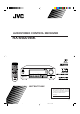
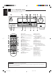
AUDIO/VIDEO CONTROL RECEIVER RX-6500VBK POWER TV VCR AUDIO TV SOUND/ DBS VCR SLEEP ANALOG/DIGITAL PHONO CATV/ SAT DVD CD TAPE/MD D I G I T A L FM/AM 3 8 REC PAUSE SURROUND SOUND SURROUND CATV CH MODE MASTER VOLUME CATV CONTROL 7 RX-6500V AUDIO/VIDEO CONTROL RECEIVER D I G I T A L – ADJUST VCR CH CD - DISC POWER SUBWOOFER 2 1 SETTING CNTR 3 4 MEMORY REAR•R REAR•L 5 6 EFFECT TEST 9 0 TV/ VIDEO 7/P THEATER +10 DVD RETURN 100+ TV VOL TV SOUND/DBS DANCE CLUB
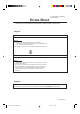
RX-6000VBK/RX-6008VBK[J]/ RX-6500VBK[J] Errata Sheet Please notice the following modifications when reading Instructions. Page 18. Incorrect Notes: • If “REAR SPK” and “CENTER SPK” are set to “NONE,” — you can select only “HEAD PHONE” or “OFF” for the DSP mode. — you cannot select Surround mode. • No sounds come out of the center speaker, even if it is connected. Correct Notes: • If “REAR SPK” and “CENTER SPK” are set to “NONE,” you cannot select Surround mode.
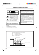
Warnings, Cautions and Others CAUTION Caution –– POWER switch! Disconnect the mains plug to shut the power off completely. The POWER switch in any position does not disconnect the mains line. The power can be remote controlled. RISK OF ELECTRIC SHOCK DO NOT OPEN CAUTION: TO REDUCE THE RISK OF ELECTRIC SHOCK. DO NOT REMOVE COVER (OR BACK) NO USER SERVICEABLE PARTS INSIDE. REFER SERVICING TO QUALIFIED SERVICE PERSONNEL. For U.S.A.
Parts Identification ...................................... 2 Using the DSP Modes ................................ 18 Getting Started ........................................... 3 Available DSP Modes According to the Speaker Arrangement .. 20 Adjusting the 3D-PHONIC Modes .......................................... 21 Adjusting the DAP Modes and Headphones mode .................. 21 Adjusting the Surround Modes ................................................ 22 Activating the DSP Modes ..................
English Parts Identification Become familiar with the buttons and controls on the receiver before use. Refer to the pages in parentheses for details. Ÿ ~ @¤ ! ⁄ # ‹ $ › MASTER VOLUME RX-6500V AUDIO/VIDEO CONTROL RECEIVER D I G I T A L – + STANDBY ADJUST POWER SETTING MEMORY THEATER DVD TV SOUND/DBS LIVE CLUB DANCE CLUB HALL ONE TOUCH OPERATION/ INPUT ATT. PHONO FM/AM SOURCE NAME CD SPEAKERS 1 PHONES TAPE/MD PAVILLION VCR DSP.
English Getting Started This section explains how to connect audio/video components and speakers to the receiver, and how to connect the power supply. Before Installation General • Be sure your hands are dry. • Turn the power off to all components. • Read the manuals supplied with the components you are going to connect.
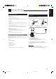
English Basic connecting procedure AM Antenna Connections Snap the tabs on the loop frame into the slots of the base to assemble the AM loop. ANTENNA FM 75 COAXIAL 2 1 3 4 1 1 RIG RIG AM Loop Antenna RIG HT HT AM LOOP 1 HT 1 Cut, twist and remove the insulation at the end of each speaker signal cable (not supplied). AM EXT 2 Turn the knob counterclockwise. 1 2 3 3 Insert the speaker signal cable. 4 Turn the knob clockwise.
English Connecting the subwoofer speaker Turntable You can enhance the bass by connecting a subwoofer. Connect the input jack of a powered subwoofer to the SUBWOOFER OUT jack on the rear panel, using a cable with RCA pin plugs (not supplied).
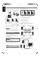
English Video component connections Use the cables with RCA pin plugs (not supplied). Connect the white plug to the audio left jack, the red plug to the audio right jack, and the yellow plug to the video jack. IMPORTANT: TV and/or DBS tuner When connecting the TV to the TV SOUND/DBS jacks, DO NOT connect the TV’s video output to the video input terminal. RIGHT This receiver is equipped with both the composite video and S-video input terminals for connecting video components.
English Digital connections Connecting the Power Cord This receiver is equipped with one DIGITAL OUT terminal and three DIGITAL IN terminals — one digital coaxial terminal and two digital optical terminal. You can connect any digital equipment such as DBS tuner, DVD player, CD player, and MD recorder to one of the digital terminals using a digital coaxial cable (not supplied) or digital optical cable (not supplied).
English Basic Operations The following operations are commonly used when you play any sound source. Turning the Power On and Off (Standby) Selected source name appears On the front panel: STANDBY To turn on the power, press POWER. The STANDBY lamp goes off. The name of the current source (or station frequency) appears on the display. Current source name appears POWER DVD Current volume level is shown here To turn off the power (into standby mode), press POWER again. The STANDBY lamp lights up.
On the front panel: SOURCE NAME TAPE/MD PHONO FM/AM SOURCE NAME From the remote control: TV SOUND/ DBS CD Notes: • Once you have selected a video source, pictures of the selected source are sent to the TV until you select another video source. * Except when your TV is connected through the AV COMPU LINK remote control system (see page 27). Adjusting the Volume 2 _ ON — OFF Listening only with headphones 1. Connect a pair of headphones to the PHONES jack on the front panel. 2.
English Adjusting the Subwoofer Output Level Reinforcing the Bass You can adjust the subwoofer output level if you have selected “YES” for the “SUBWOOFER” (see page 15). Once it has been adjusted, the receiver memorizes the adjustment. Before you start, remember... • There is a time limit in doing the following steps. If the setting is canceled before you finish, start from step 1 again. Before you start, remember... • There is a time limit in doing the following steps.
Some of the following settings are required after connecting and positioning your speakers in your listening room, while others will make operations easier. Recording a Source Changing the Source Name For analog-to-analog recording You can record any source playing through the receiver to a cassette deck (or an MD recorder) connected to the TAPE/MD jacks and the VCR connected to the VCR jacks at the same time.
English Setting the Speakers for the DSP Modes To obtain the best possible surround sound of the DSP (Digital Signal Processor) modes (see page 18), you have to register the information about the speakers arrangement after all connections are completed. Before you start, remember... • There is a time limit in doing the following steps. If the setting is canceled before you finish, start from step 1 again.
Low Frequency Effect Attenuator Setting Small speaker cannot reproduce the bass sound very well. So, if you have used a small speaker any for the front, center, or rear channels, this receiver automatically reallocates the bass elements, originally assigned to the channel for which you have connected the small speaker, to another channel (for which you have connected the large speaker). If you have selected “LARGE” for all speakers (see page 12), this function will not take effect.
English 1. Follow the steps in “Digital Input (DIGITAL IN) Terminal Setting” to the left. Digital Input (DIGITAL IN) Terminal Setting When you use the digital input terminals, you have to register what components are connected to which terminals (DIGITAL IN 1/2/3). Before you start, remember... • There is a time limit in doing the following steps. If the setting is canceled before you finish, start from step 1 again. 2.
Register whether or not you have connected a subwoofer. Before you start, remember... • There is a time limit in doing the following steps. If the setting is canceled before you finish, start from step 1 again. On the front panel ONLY: SETTING 1. Press SETTING repeatedly until “SUBWOOFER” appears on the display. To cancel the One Touch Operation function Press ONE TOUCH OPERATION (INPUT ATT.) so that the ONE TOUCH OPERATION indicator goes off.
English Receiving Radio Broadcasts You can browse through all the stations or use the preset function to go immediately to a particular station. Tuning in Stations Manually Using Preset Tuning On the front panel ONLY: 1. Press FM/AM to select the band. FM/AM The MULTI CURSOR % / fi / @ / # buttons can be now used for operating the tuner. • Each time you press the button, the band alternates between FM and AM. Once a station is assigned to a channel number, the station can be quickly tuned.
English To tune in a preset station Selecting the FM Reception Mode On the front panel: 1. Press FM/AM to select the band. FM/AM • The MULTI CURSOR % / fi / @ / # buttons can be now used for operating the tuner. • Each time you press the button, the band alternates between FM and AM. When an FM stereo broadcast is hard to receive or noisy You can change the FM reception mode while receiving an FM broadcast. On the front panel ONLY: 1.
English Using the DSP Modes The built-in Surround Processor provides three types of the DSP (Digital Signal Processor) mode — 3D-PHONIC mode, DAP (Digital Acoustic Processor) mode and Surround mode. 3D-PHONIC modes DAP modes The 3D-PHONIC mode gives you such a nearly surround effect as it is reproduced through the Dolby Surround decoder, which is widely used to reproduce sounds with a feeling of movement like those experienced in movie theaters.
This mode can reproduce the LFE channel signals, mixing them to the front channel signals. So you will not miss the subwoofer sounds even if you listen to a source using the headphones. JVC Theater Surround In order to reproduce a more realistic sound field in your listening room while playing soundtracks of software encoded with Dolby Surround (bearing the mark DOLBY SURROUND ), you can use JVC Theater Surround. Surround modes With this receiver, you can use three types of the Surround mode.
English Available DSP Modes According to the Speaker Arrangement Available DSP modes will vary depending on how many speakers are used with this receiver. Make sure that you have set the speaker information correctly (see page 12).
Adjusting the DAP Modes and Headphones mode Once you have adjusted the 3D-PHONIC modes, the adjustment is memorized for each 3D-PHONIC mode. Before you start, remember... • Make sure that you have set the speaker information correctly (see page 12). • There is a time limit in doing the following steps. If the setting is canceled before you finish, start from step 1 again. On the front panel: DSP MODE 1. Press DSP MODE repeatedly until “3D ACTION” or “3D THEATER” appears on the display.
English From the remote control: 1. Press SURROUND MODE repeatedly until the DAP mode — LIVE CLUB, DANCE CLUB, HALL, PAVILION, or HEAD PHONE — appears on the display. SURROUND MODE Once you have adjusted the Surround modes, the adjustment is memorized for each Surround mode. Dolby and DTS Surround adjustments Before you start, remember... • Make sure that you have set the speaker information correctly (see page 12). • There is a time limit in doing the following steps.
• To adjust the center speaker level, press CNTR –/+ (from –10 dB to +10 dB). • To adjust the left rear speaker level, press REAR•L –/+ (from –10 dB to +10 dB). • To adjust the right rear speaker level, press REAR•R –/+ (from –10 dB to +10 dB). JVC Theater Surround adjustments CNTR 3 4 REAR•L 5 6 MENU ENTER Before you start, remember... • Make sure that you have set the speaker information correctly (see page 12). • There is a time limit in doing the following steps.
English 4. Adjust the speaker output levels. CNTR • To adjust the center speaker level, press CNTR –/+ (from –10 dB to +10 dB). • To adjust the left rear speaker level, press REAR•L –/+ (from –10 dB to +10 dB). • To adjust the right rear speaker level, press REAR•R –/+ (from –10 dB to +10 dB). 3 4 REAR•L 5 6 MENU ENTER REAR•R 7/P 5. Press TEST again to stop the test tone. 6. Press EFFECT to select an effect level you want.
English Activating the DSP Modes For the other DSP modes You can use only one DSP mode at a time. When a DSP mode is activated, another DSP mode is canceled if in use. For Dolby Pro Logic, Dolby Digital, and DTS Digital Surround On the front panel: 1. Press DSP MODE repeatedly until the mode you want appears on the display. DSP MODE • Each time you press the button, the DSP modes change. (See page 20 for more details.) On the front panel: 1.
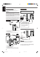
English COMPU LINK Remote Control System The COMPU LINK remote control system allows you to operate JVC audio components through the remote sensor on the receiver. To use this remote control system, you need to connect JVC audio components through the COMPU LINK-3 (SYNCHRO) jacks (see below) in addition to the connections using cables with RCA pin plugs (see page 5). • Make sure that the AC power cords of these components are unplugged before connection.
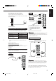
The AV COMPU LINK remote control system allows you to operate JVC video components (TV, VCR, and DVD player) through the receiver. To use this remote control system, you need to connect the video components you want to operate, follow the diagrams below and the procedure on the next page. CONNECTIONS 1: CAUTION TV VCR The AV COMPU LINK remote control system cannot control the DBS tuner connected to the TV SOUND/DBS jacks.
English 1. If you have already plugged your VCR, DVD player, TV, and this receiver into the AC outlets, unplug their AC power cords first. 2. Connect your VCR, DVD player, TV, and this receiver, using the cables with the monaural miniplugs (not supplied). • See “CONNECTIONS 1” on the previous page. 3. Connect the audio input/output jacks on VCR, DVD player, TV, and this receiver using the cables with RCA pin plug • See pages 5 and 6.
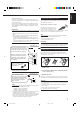
You can operate JVC’s audio and video components with this receiver’s remote control, since control signals for JVC components are preset in the remote control. IMPORTANT: To operate JVC’s audio components using this remote control: • You need to connect JVC audio components through the COMPU LINK-3 (SYNCHRO) jacks (see page 26) in addition to the connections using cables with RCA pin plugs (see page 5). • Aim the remote control directly at the remote sensor on the receiver.
English CD player-changer IMPORTANT: After pressing CD-DISC, you can perform the following operations on a CD player-changer: To operate JVC’s video components using this remote control: • You need to connect JVC video components through the AV COMPU LINK terminals (see page 27) in addition to the connections using cables with RCA pin plugs (see page 6). • Some JVC VCRs can accept two types of the control signals — remote code “A” and “B.
This remote control supplied with the receiver can transmit control signals for other manufacturers’ VCRs, TVs, CATV converters and satellite tuners. By changing the transmittable signals from preset ones to the other manufacturers’, you can operate the other manufacturer’s components using this remote control. To change the transmittable signals for operating another manufacturer’s TV When operating the other manufacturers’ components, refer also to the manuals supplied with them.
English To change the transmittable signals for operating another manufacturer’s VCR To change the transmittable signals for operating a CATV converter or satellite tuner 1. Press and hold CATV/SAT POWER. 1. Press and hold VCR POWER. 2. Press CATV CONTROL. 2. Press VCR. 3. Enter manufacturer’s code (two digits) using buttons 1–9, and 0. See the list below to find the code. Examples: For a PANASONIC product, press 0, then 7. For a MITSUBISHI product, press 1, then 3. 4. Release VCR POWER. 3.
Use this chart to help you solve daily operational problems. If there is any problem you cannot solve, contact your JVC service center. PROBLEM POSSIBLE CAUSE SOLUTION The display does not light up. The power cord is not plugged in. Plug the power cord into an AC outlet. No sound from speakers. Speaker signal cables are not connected. Check speaker wiring and reconnect if necessary. The SPEAKERS 1 and 2 buttons are not set correctly. Press SPEAKERS 1 and 2 correctly.
English Specifications Amplifier Output Power At Stereo operation: Front channels: 100 W per channel, min. RMS, driven into 8 Ω 40 Hz to 20 kHz with no more than 0.8% total harmonic distortion. At Surround operation: Audio Audio Input Sensitivity/Impedance (1 kHz): Audio Input (DIGITAL IN)* : Front channels: 100 W per channel, min. RMS, driven into 8 Ω at 1 kHz with no more than 0.8% total harmonic distortion. Center channel: 100 W, min. RMS, driven into 8 Ω at 1 kHz, with no more than 0.
English FM tuner (IHF) Tuning Range: 87.5 MHz to 108.0 MHz Usable Sensitivity: Monaural: 12.8 dBf (1.2 µV/75 Ω) 50 dB Quieting Sensitivity: Monaural: Stereo: 21.3 dBf (3.2 µV/75 Ω) 41.3 dBf (31.5 µV/75 Ω) Signal-to-Noise Ratio (IHF-A weighted): Monaural: Stereo: 78 dB at 85 dBf 73 dB at 85 dBf Total Harmonic Distortion: Monaural: Stereo: 0.4% at 1 kHz 0.
QUALITY SERVICE HOW TO LOCATE YOUR JVC SERVICE CENTER TOLL FREE : 1-800-537-5722 http://www.jvcservice.com Dear customer: In order to receive the most satisfaction from your purchase, read the instruction booklet before operating the unit. In the event that repair is necessary, or for the address nearest your location, please refer to the factory service center list below or within the Continental United States, Call 1-800-537-5722 for your authorized servicer.
LIMITED WARRANTY AUDIO-2 JVC COMPANY OF AMERICA warrants this product and all parts thereof, except as set forth below ONLY TO THE ORIGINAL PURCHASER AT RETAIL to be FREE FROM DEFECTIVE MATERIAL AND WORKMANSHIP from the date of original retail purchase for the period as shown below. (“The Warranty Period.”) PARTS LABOR 2YR 2YR THIS LIMITED WARRANTY IS VALID ONLY IN THE FIFTY(50) UNITED STATES, THE DISTRICT OF COLUMBIA AND IN COMMONWEALTH OF PUERTO RICO.
VICTOR COMPANY OF JAPAN, LIMITED V EN RX-6500V[J]COVER/1 J 2 99.12.