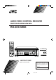
AUDIO/VIDEO CONTROL RECEIVER RECEPTEUR DE CONTROL AUDIO/VIDEO RX-6510VBK CATV/DBS VCR POWER POWER POWER POWER CD FM/AM VCR TAPE/CDR TV DVD TV SOUND − BASS + SURROUND DSP ON/OFF MODE − AUDIO TREBLE + ANALOG/DIGITAL SLEEP INPUT + CENTER – BASS BOOST EFFECT 1 2 3 MENU TEST + REAR•L – 4 5 6 ENTER 7/P CATV/DBS CONTROL TV/VIDEO 8 − 9 FM/AM TUNING – SUB WOOFER + 10 0 +10 RETURN FM MODE 100+ + + + CH TV VOL VOLUME FM/AM PRESET FM MODE STANDBY MASTER VOLUME
Warnings, Cautions and Others/ Mises en garde, précautions et indications diverses CAUTION RISK OF ELECTRIC SHOCK DO NOT OPEN CAUTION: TO REDUCE THE RISK OF ELECTRIC SHOCK. DO NOT REMOVE COVER (OR BACK) NO USER SERVICEABLE PARTS INSIDE. REFER SERVICING TO QUALIFIED SERVICE PERSONNEL.
English For Canada/pour Le Canada Français THIS DIGITAL APPARATUS DOES NOT EXCEED THE CLASS B LIMITS FOR RADIO NOISE EMISSIONS FROM DIGITAL APPARATUS AS SET OUT IN THE INTERFERENCE-CAUSING EQUIPMENT STANDARD ENTITLED “DIGITAL APPARATUS,” ICES-003 OF THE DEPARTMENT OF COMMUNICATIONS.
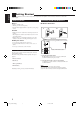
English Table of Contents Parts Identification ...................................... 2 Getting Started ........................................... 3 Before Installation ...................................................................... 3 Checking the Supplied Accessories ........................................... 3 Connecting the FM and AM Antennas ....................................... 3 Connecting the Speakers ............................................................
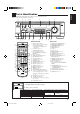
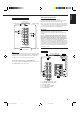
English Parts Identification Become familiar with the buttons and controls on the receiver before use. Refer to the pages in parentheses for details.
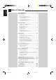
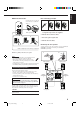
English Getting Started This section explains how to connect audio/video components and speakers to the receiver, and how to connect the power supply. Before Installation Connecting the FM and AM Antennas FM Antenna Connections General • Be sure your hands are dry. • Turn the power off to all components. • Read the manuals supplied with the components you are going to connect.
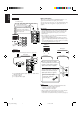
Snap the tabs on the loop into the slots of the base to assemble the AM loop. ANTENNA FM 75 COAXIAL 2 1 AM LOOP AM Loop Antenna 4 3 1 1 RIG HT AM EXT English Basic connecting procedure AM Antenna Connections 1 RIG HT RIG HT 1 Cut, twist and remove the insulation at the end of each speaker signal cable (not supplied). 2 Turn the knob counterclockwise. 2 1 3 3 Insert the speaker signal cable. 4 Turn the knob clockwise.
English About the speaker impedance Connecting the subwoofer speaker The required speaker impedance of the front speakers does differ depending on whether both the FRONT SPEAKERS 1 and FRONT SPEAKERS 2 terminals are used or only one of them is used. You can enhance the bass by connecting a subwoofer. Connect the input jack of a powered subwoofer to the SUBWOOFER OUT jack on the rear panel, using a cable with RCA pin plugs (not supplied).
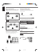
Cassette deck To audio input To audio output PHONO CD CD Video component connections Use the cables with RCA pin plugs (not supplied). Connect the white plug to the audio left jack, the red plug to the audio right jack, and the yellow plug to the video jack. If your video components have S-video (Y/C-separation) terminals, connect them using S-video cables (not supplied).
English Digital connections TV This receiver is equipped with two DIGITAL IN terminals — one digital coaxial terminal and one digital optical terminal. You can connect any component to one of the digital terminals using a digital coaxial cable (not supplied) or digital optical cable (not supplied). To S-video input To composite video input PHONO Connect the TV to the MONITOR OUT jack to view the playback CD picture from the other connected video components.
Before plugging the receiver into an AC outlet, make sure that all connections have been made. English Connecting the Power Cord Putting Batteries in the Remote Control Before using the remote control, put two supplied batteries first. When using the remote control, aim the remote control directly at the remote sensor on the receiver. Plug the power cord into an AC outlet. 1 Keep the power cord away from the connecting cables and the antenna. The power cord may cause noise or screen interference.
English Basic Operations The following operations are commonly used when you play any sound source. Turning the Power On and Off (Standby) On the front panel: To turn on the power, press POWER. The STANDBY lamp goes off. The name of the current source (or station frequency) appears on the display. R VOLUME Current volume level is shown here To turn off the power (into standby mode), press POWER again. The STANDBY lamp lights up. A small amount of power is consumed in standby mode.
You can watch picture from a video component while listening to sound from another component. Selecting the Front Speakers On the front panel ONLY: When you have connected two pairs of the front speakers, you can select which to use. Press one of the audio source selecting buttons — CD, TAPE/CDR, FM/AM, TV SOUND (or TV SOUND on the remote control), while viewing the picture from a video component such as the VCR or DVD player, etc.
English From the remote control: Muting the Sound From the remote control ONLY: Press MUTING to mute the sound through all speakers and headphones connected. MUTING “MUTING” appears on the display and the volume turns off (the volume level indicator goes off). Press BASS +/– or TREBLE +/– to adjust the bass or treble sound level (+10 dB to –10 dB). − BASS − TREBLE + + Attenuating the Input Signal To restore the sound, press MUTING again so that “OFF” appears on the display.
Some of the following settings are required after connecting and positioning your speakers in your listening room, while others will make operations easier. Recording a Source Changing the Source Name You can record any source playing through the receiver to a cassette deck (or a CD recorder) connected to the TAPE/CDR jacks and the VCR connected to the VCR jacks at the same time.
English Setting the Speakers for the DSP Modes To obtain the best possible surround sound of the DSP modes, you have to register the information about the speakers arrangement after all connections are completed. Before you start, remember.... • There is a time limit in doing the following steps. If the setting is canceled before you finish, start from step 1 again.
Small speakers cannot reproduce the bass sound very well. So, if you have used a small speaker for any of the front, center, and rear channels, this receiver automatically reallocate the bass elements, originally assigned to the channel for which you have connected the small speaker, to another channel (for which you have connected the large speaker). To use this function properly, you need to set the crossover frequency level according to the size of the small speaker connected.
English Digital Input (DIGITAL IN) Terminal Setting When you use the digital input terminals, you have to register what components are connected to which terminals (DIGITAL IN 1/2). Before you start, remember... • There is a time limit in doing the following steps. If the setting is canceled before you finish, start from step 1 again. On the front panel ONLY: 1. Press SETTING repeatedly until “DIGITAL IN” appears on the display.
In this case, press CONTROL UP 5/ DOWN ∞ to select “DTS” while “AUTO” is lit on the display. • Each time you press the button, the input mode changes as follows: AUTO DTS (Digital) (Digital) English When playing a software encoded with the DTS Digital Surround, “AUTO” may not work properly and the following symptoms may occur: • Sound does not come out at the beginning of playback. • Noise comes out while using the searching or skipping function.
English Receiving Radio Broadcasts You can browse through all the stations or use the preset function to go immediately to a particular station. Tuning in Stations Manually Using Preset Tuning On the front panel: Once a station is assigned to a channel number, the station can be quickly tuned. You can preset up to 30 FM and 15 AM stations. 1. Press FM/AM to select the band (FM or AM). FM/AM The last received station of the selected band is tuned in.
English Selecting the FM Reception Mode To tune in a preset station On the front panel: 1. Press FM/AM to select the band (FM or AM). When an FM stereo broadcast is hard to receive or noisy FM/AM You can change the FM reception mode while receiving an FM broadcast. • You can store the FM reception mode for each preset station. The last received station of the selected band is tuned in. 2. Press FM/AM PRESET 5/ ∞ until you find the channel you want.
English Using the DSP Modes The built-in Surround Processor provides two types of the DSP (Digital Signal Processor) mode — Surround mode and DAP (Digital Acoustic Processor) mode. What are the DSP Modes? Surround modes With this receiver, you can use three types of the Surround mode. Following modes cannot be used when only the front speakers are connected to this receiver (without the rear speakers or center speaker).
In order to reproduce a more acoustic sound field in your listening room while playing soundtracks of stereo sources, you can use DAP modes. This mode can be used when the front speakers and the rear speakers are connected to this receiver (without respect to the center speaker connection). You can select one of the following to your preference.
English Available DSP Modes According to the Speaker Arrangement Available DSP modes will vary depending on how many speakers are used with this receiver. Make sure that you have set the speaker information correctly (see page 13).
5. Adjust the speaker output levels. Once you have adjusted the Surround modes, the adjustment is memorized for each Surround mode. Dolby and DTS Surround adjustments Before you start, remember... • Make sure that you have set the speaker information correctly (see page 13). • There is a time limit in doing the following steps. If the setting is canceled before you finish, start from step 3 again. • You cannot adjust the rear speaker output levels when you have set “REAR SPK” to “NO.” See page 13.
English JVC Theater Surround adjustments TEST 5. Press TEST again to stop the test tone. Before you start, remember... • Make sure that you have set the speaker information correctly (see page 13). • There is a time limit in doing the following steps. If the setting is canceled before you finish, start from step 2 again. • You cannot adjust the rear speaker output levels when you have set “REAR SPK” to “NO.” See page 13.
English From the remote control: Adjusting the DAP Modes Once you have adjusted the DAP modes, the adjustment is memorized for each DAP mode. Before you start, remember... • Make sure that you have set the speaker information correctly (see page 13). • There is a time limit in doing the following steps. If the setting is canceled before you finish, start from step 1 again. • You cannot adjust the rear speaker output level when you have set “REAR SPK” to “NO.” See page 13. 1.
English Activating the DSP Modes For the other DSP modes You can use only one DSP mode at a time. When a DSP mode is activated, another DSP mode is canceled if in use. For Dolby Pro Logic, Dolby Digital, and DTS Digital Surround 1. Press DSP MODE repeatedly until the mode you want appears on the display. • Each time you press the button, the DSP modes change. (See page 21 for more details.) DSP MODE 1. Press SURROUND ON/OFF.
The COMPU LINK remote control system allows you to operate JVC audio components through the remote sensor on the receiver. To use this remote control system, you need to connect JVC audio components through the COMPU LINK (SYNCHRO) jacks (see below) in addition to the connections using cables with RCA pin plugs (see pages 5 and 6). • Make sure that the AC power cords of these components are unplugged before connection. Plug the AC power cords only after all connections are complete.
English Operating JVC’s Audio/Video Components You can operate JVC’s audio and video components with this receiver’s remote control, since control signals for JVC components are preset in the remote control.
After pressing CONTROL repeatedly until “CDDSC” appears on the display window, you can perform the following operations on the CD changer: PLAY3: 4: ¢: STOP7: PAUSE8: 1 – 6, 7/P: Starts playing. Returns to the beginning of the current (or previous) track. Skips to the beginning of the next track. Stops playing. Pauses playing. To release it, press PLAY3. Selects the number of a disc installed in a CD changer.
English Operating Video Components VCR You can always perform the following operations: VCR POWER: IMPORTANT: To operate JVC’s video components using this remote control: • Some JVC VCRs can accept two types of the control signals — remote code “A” and “B.” Before using this remote control, make sure that the remote control code of the VCR connected to the VCR jacks is set to code “A.
This remote control supplied with the receiver can transmit control signals for other manufacturers’ VCRs, TVs, CATV converters, DBS tuners, and DVD players. By changing the transmittable signals from preset ones to the other manufacturers’, you can operate the other manufacturer’s components using this remote control. To change the transmittable signals for operating another manufacturer’s TV When operating the other manufacturers’ components, refer also to the manuals supplied with them.
English To change the transmittable signals for operating a CATV converter or DBS tuner 1. Press and hold CATV/DBS POWER. For CATV converter Manufacturer Codes 2. Press CATV/DBS CONTROL. GENERAL INSTRUMENT 3. Enter manufacturer’s code using buttons 1–9, and 0. HAMLIN/REGAL JERROLD 06, 07, 08, 09, 10, 11, 12, 13, 14, 29 01, 02, 03, 04, 05 06, 07, 08, 09, 10, 11, 12, 13, 14 15, 16, 17 18, 19, 20 21, 22 23, 24, 25 26 27, 28 See the list to the right to find the code. 4. Release CATV/DBS POWER.
English To change the transmittable signals for operating another manufacturer’s VCR 1. Press and hold VCR POWER. 2. Press VCR. 3. Enter manufacturer’s code using buttons 1–9, and 0. See the list to the right to find the code. 4. Release VCR POWER. The following button can be used for operating the VCR: VCR POWER: Turns on and off the VCR. After pressing VCR, you can perform the following operations on the VCR: CH +/–: Changes the TV channels on the VCR. 1 – 10, 0, 100+ (+10): Selects the TV channels.
English To change the transmittable signals for operating another manufacturer’s DVD player 1. Press and hold AUDIO POWER. Manufacturer 2. Press DVD. 3. Enter manufacturer’s code using buttons 1–9, and 0. See the list to the right to find the code. 4. Release AUDIO POWER. After pressing DVD, you can perform the following operations on a DVD player: PLAY3: 4: ¢: STOP7: PAUSE8: Starts playing. Returns to the beginning of the current (or previous) tracks. Skips to the beginning of the next track.
Use this chart to help you solve daily operational problems. If there is any problem you cannot solve, contact your JVC service center. PROBLEM SOLUTION POSSIBLE CAUSE The display does not light up. The power cord is not plugged in. Plug the power cord into an AC outlet. No sound from speakers. Speaker signal cables are not connected. Check speaker wiring and reconnect if necessary. The SPEAKERS ON/OFF 1 and 2 buttons are not set correctly. Press SPEAKERS ON/OFF 1 and 2 correctly.
English Specifications Amplifier Output Power At Stereo operation: Front channels: 100 W per channel, min. RMS, driven into 8 Ω, 40 Hz to 20 kHz with no more than 0.8% total harmonic distortion. At Surround operation: Audio Audio Input Sensitivity/Impedance (1 kHz): Audio Input (DIGITAL IN)* : Front channels: 100 W per channel, min. RMS, driven into 8 Ω at 1 kHz with no more than 0.8% total harmonic distortion. Center channel: 100 W, min. RMS, driven into 8 Ω at 1 kHz, with no more than 0.
English FM tuner (IHF) Tuning Range: 87.5 MHz to 108.0 MHz Usable Sensitivity: Monaural: 12.8 dBf (1.2 µV/75 Ω) 50 dB Quieting Sensitivity: Monaural: Stereo: 21.3 dBf (3.2 µV/75 Ω) 41.3 dBf (31.5 µV/75 Ω) Signal-to-Noise Ratio (IHF-A weighted): Monaural: Stereo: 78 dB at 85 dBf 73 dB at 85 dBf Total Harmonic Distortion: Monaural: Stereo: 0.4% at 1 kHz 0.
VICTOR COMPANY OF JAPAN, LIMITED V EN, FR RX-6510VBK[C]COVER_f J 2 00.12.