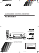
AUDIO/VIDEO CONTROL RECEIVER RX-668VBK CATV/SAT TV POWER VCR AUDIO CATV CONTROL CD-DISC DELAY TEST 1 SOUND CONTROL SURROUND 2 EFFECT 3 – CENTER + 4 5 MENU 6 – REAR•L + 8 7/P 100+ 9 – REAR•R + 0 +10 RETURN 10 ENTER SET VOLUME CH TV VOL.
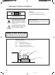
Warnings, Cautions and Others CAUTION CAUTION To reduce the risk of electrical shocks, fire, etc.: 1. Do not remove screws, covers or cabinet. 2. Do not expose this appliance to rain or moisture. RISK OF ELECTRIC SHOCK DO NOT OPEN CAUTION: TO REDUCE THE RISK OF ELECTRIC SHOCK. DO NOT REMOVE COVER (OR BACK) NO USER SERVICEABLE PARTS INSIDE. REFER SERVICING TO QUALIFIED SERVICE PERSONNEL.
Table of Contents Parts Identification ...................................... 2 Using the DVD MULTI Playback Mode .......... 20 Getting Started ........................................... 3 Activating the DVD MULTI Playback Mode .......................... 20 Before Installation ...................................................................... 3 Checking the Supplied Accessories ........................................... 3 Connecting the FM and AM Antennas .......................................
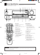
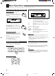
Parts Identification Become familiar with the buttons and controls on the receiver before use. Refer to the pages in parentheses for details. 1 2 3 4 5 6 7 8 9 MASTER VOLUME RX-668V AUDIO/VIDEO CONTROL RECEIVER – + STANDBY BASS BOOST POWER ADJUST SETTING MEMORY DVD MULTI DVD VCR TV SOUND CD PHONO TAPE/MD FM/AM SURROUND ONE TOUCH OPERATION SPEAKERS 1 PHONES 2 INPUT ATT.
Getting Started This section explains how to connect audio/video components and speakers to the receiver, and how to connect the power supply. Before Installation General • Be sure your hands are dry. • Turn the power off to all components. • Read the manuals supplied with the components you are going to connect.
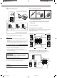
Basic connecting procedure AM Antenna Connections Snap the tabs on the loop into the slots of the base to assemble the AM loop. ANTENNA FM 75 COAXIAL AM LOOP AM EXT 1 AM Loop Antenna 2 3 1 3 2 1 Cut, twist and remove the insulation at the end of each speaker signal cable. 2 Open the terminal and then insert the speaker signal cable. 3 Close the terminal.
Connecting the subwoofer speaker CD player You can enhance the bass by connecting a subwoofer. Connect the input jack of a powered subwoofer to the SUBWOOFER OUT jack on the rear panel, using a cable with RCA pin plugs.
Video component connections DVD player Use the cables with RCA pin plugs (not supplied). Connect the white plug to the audio left jack, the red plug to the audio right jack, and the yellow plug to the video jack. If DVD player and TV have S-video (Y/C-separation) terminals, connect them using S-video cables (not supplied). Connecting these video components through the S-video input/output terminals will give you better picture playback quality.
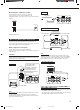
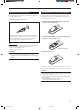
Connecting the Power Cord Before plugging the receiver into an AC outlet, make sure that all connections have been made. Putting Batteries in the Remote Control Before using the remote control, put two supplied batteries first. When using the remote control, aim the remote control directly at the remote sensor on the receiver. Plug the power cord into an AC outlet. 1. On the back of the remote control, remove the battery cover as illustrated.
Basic Operations The following operations are commonly used when you play any sound source. Turning the Power On and Off (Standby) Selected source name appears On the front panel: To turn on the power, press POWER. The STANDBY lamp goes off. The name of the current source (or station frequency) appears on the display.
Listening only with headphones Adjusting the Volume On the front panel: To increase the volume, turn MASTER VOLUME clockwise. To decrease the volume, turn it counterclockwise. • When you turn MASTER VOLUME rapidly, the volume level also changes rapidly. • When you turn MASTER VOLUME slowly, the volume level also changes slowly. MASTER VOLUME + – 1. Connect a pair of headphones to the PHONES jack on the front panel. 2. Press SPEAKERS 1 and SPEAKERS 2 to set them in the — OFF position.
Attenuating the Input Signal output (from “R-21” to “L-21”). When the input level of the playing source is too high, the sounds will be distorted. If this happens, you need to attenuate the input signal level to prevent the sound distortion. Reinforcing the Bass With this Bass Boost function, you can boost the bass level. INPUT ATT. On the front panel ONLY: Press INPUT ATT. so that the lamp next to the button lights up. The ATT indicator also lights up on the display.
Basic Settings Some of the following settings are required after connecting and positioning your speakers in your listening room, while others will make operations easier. 3. Press cursor control @ / # to select your center speaker size. Changing the Source Name When you have connected an MD recorder to the TAPE/MD jacks on the rear panel: Change the source name shown on the display when you select the MD recorder as the source.
On the front panel: 1. Press SETTING so that the cursor control % / fi buttons work for setting the delay time. SETTING JVC’s One Touch Operation function is used to assign and store different sound settings for each different playing source. By using this function, you don’t have to change the settings every time you change the source. The stored settings for the newly selected source are automatically recalled. 2. Press cursor control % / fi repeatedly until “DELAY TIME” appears on the display. 3.
Receiving Radio Broadcasts You can browse through all the stations or use the preset function to go immediately to a particular station. Tuning in Stations Manually Using Preset Tuning On the front panel ONLY: FM/AM 1. Press FM/AM to select the band. The cursor control % / fi / @ / # buttons can be now used for operating the tuner. • Each time you press the button, the band alternates between FM and AM. Once a station is assigned to a channel number, the station can be quickly tuned.
To tune in a preset station Selecting the FM Reception Mode On the front panel: FM/AM When an FM stereo broadcast is hard to receive or noisy 1. Press FM/AM to select the band. The cursor control % / fi / @ / # buttons can be now used for operating the tuner. • Each time you press the button, the band alternates between FM and AM. You can change the FM reception mode while receiving an FM broadcast. On the front panel ONLY: EON 100 1k FM/AM 1. Press FM/AM to select the band.
Using the DSP Modes The built-in Surround Processor provides three types of the DSP (Digital Signal Processor) mode — 3D-PHONIC mode, DAP (Digital Acoustic Processor) mode and Surround mode (Dolby Pro Logic and JVC Theater Surround.) 3D-PHONIC modes Surround Modes The 3D-PHONIC mode gives you such a nearly surround effect as it is reproduced through the Dolby Surround decoder, which is widely used to reproduce sounds with a feeling of movement like those experienced in movie theaters.
Available DSP Modes According to the Speaker Arrangement Available DSP modes will vary depending on how many speakers are used with this receiver. Make sure that you have set the speaker information correctly (see page 11).
Adjusting the 3D-PHONIC Modes Adjusting DAP (Digital Acoustic Processor) Modes Before you start, remember... • Make sure that you have set the speaker information correctly (see page 11). • There is a time limit in doing the following steps. If the setting is canceled before you finish, start from step 1 again. On the front panel: SURROUND 1. Press SURROUND repeatedly until “3D ACTION” or “3D THEATER,” appears on the display.
From the remote control: 3. Press TEST to check the speaker output balance. SOUND CONTROL 1. Press SOUND CONTROL. The 10 keys are activated for sound adjustments. 2. Press SURROUND repeatedly until the DAP mode — LIVE CLUB, DANCE CLUB, HALL, or PAVILION — appears on the display. SURROUND 3. Press REAR•L – / + to adjust the rear speaker output level. – REAR•L + 8 9 • Pressing REAR•L – decreases the output level up to –10 dB. • Pressing REAR•L + increases the output level up to +10 dB.
On the front panel: You can also use the buttons on the front panel to adjust the Surround modes. However, no test tone is available when using the buttons on the front panel. So, make adjustments while listening to the sound of the source played back. 1. Press SURROUND repeatedly until the mode — “PRO LOGIC” or “THEATER” — appears on the display. SURROUND Press cursor control @ / # to select an effect level you want.
Using the DVD MULTI Playback Mode This receiver provides the DVD MULTI playback mode for reproducing the analog discrete output mode of the DVD player. Before playing back a DVD, refer also to the manual supplied with the DVD player. Activating the DVD MULTI Playback Mode You can adjust the DVD MULTI playback mode while playing back a DVD using the analog discrete output mode on the DVD player. Once you made adjustments, the receiver memorizes the adjustments until you change them.
Using the On-Screen Menus You can use the Menus on the TV screen to control the receiver. To use this function, you need to connect the TV to the MONITOR OUT jack on the rear panel (see page 6), and set the TV’s input mode to the proper position to which the receiver is connected. • When the TV’s input mode is incorrect; for example, a different video input or TV tuner mode is selected, you cannot show the Menus on the TV screen. On-Screen Operation buttons (on the remote control) 1. Press OSD SET.
4. Press % / fi to move to “INPUT ATT.” For JVC Theater Surround: “TEST TONE”: Output a test tone. “CENTER LEVEL”: Adjust the center speaker output level. ** “REAR LEVEL”: Adjust the rear speaker output level. “DSP EFFECT”: Select the effect level. 5. Press @ / # to turn the Input Attenuator mode “ATT ON” or “NORMAL.” 6. When you finish, press OSD EXIT repeatedly until the menu disappears from the TV. Adjusting the DSP Modes (Also see pages 17 – 19) 1. Press OSD SET.
Adjusting the Tone (Also see page 10) 1. Press OSD SET. Operating the Tuner (Also see pages 13 and 14) 1. Press OSD SET. 2, 8, 4, and 6 buttons on the 10 keys work as % / fi / @ / # for OSD operations. 2. Press any one of % / fi / @ / #. The MAIN MENU appears on the TV. 3. Press % / fi to move to “SOUND CONTROL,” then press @ / #. The SOUND CONTROL menu appears. 4. Press % / fi to move to “TONE CONTROL,” then press @ / #. The TONE CONTROL menu appears. 5.
COMPU LINK Remote Control System The COMPU LINK remote control system allows you to operate JVC audio components through the remote sensor on the receiver. To use this remote control system, you need to connect JVC audio components through the COMPU LINK-3 (SYNCHRO) jacks (see below) in addition to the connections using cables with RCA pin plugs (see page 5). • Make sure that the AC power cords of these components are unplugged before connection.
TEXT COMPU LINK Remote Control System The TEXT COMPU LINK remote control system has been newly developed to deal with the disc information recorded in the CD Text* and MDs. Using these information in the discs, you can operate the CD player or MD recorder equipped with the TEXT COMPU LINK remote control system through the receiver. FUNCTIONS: CONNECTIONS: To use this remote control system, you need to connect the CD player and/or MD recorder you want to operate, following the procedures below. 1.
OPERATIONS To use this remote control system, you need to connect the TV to the MONITOR OUT jack on the rear panel (see page 6), and set the TV’s input mode to the proper position to which the receiver is connected. Make sure you have connected the CD player or MD recorder equipped with the TEXT COMPU LINK remote control system. If not, you cannot use the following functions.
Searching a Disc (Only for the CD player) Search a disc by its performer: 1. Press TEXT DISPLAY while “CD” is selected as the source. The Disc Information screen appears on the TV. 2. Press % / fi to move to “SEARCH,” then press OSD SET. The DISC SEARCH screen appears . 3. Press % / fi to move to “PERFORMER”, then press OSD SET. The PERFORMER SEARCH screen appears. 4. Press % / fi / @ / # to move in front of the first character of the performer you want to search, then press OSD SET.
Search a disc by its genre: 1. Press TEXT DISPLAY while “CD” is selected as the source. The Disc Information screen appears on the TV. 2. Press % / fi to move to “SEARCH,” then press OSD SET. The DISC SEARCH screen appears. 3. Press % / fi to move to “GENRE”, then press OSD SET. The GENRE SEARCH screen appears. 4. Press % / fi to move to the genre you want to search, then press OSD SET. To show the unseen genres, press % / fi until they appear.
For the MD recorder: 4. Repeat step 3 until you finish putting a name (up to 32 characters) to this User File. You can write the disc information (disc title and song titles) into the disc. You can only write the song title for the song currently selected. • If you have the CD-MD combination deck, you can also enter the disc information (its performer, disc title, and its music genre) of normal audio CDs into the memory built in the CD-MD combination deck.
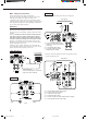
AV COMPU LINK Remote Control System The AV COMPU LINK remote control system allows you to operate JVC video components (TV, VCR, and DVD player) through the receiver. CONNECTIONS: TV VCR DVD player VHS DVD AV COMPU LINK AV COMPU LINK If the AV COMPU LINK terminal on the TV is “RECEIVER/AMP” AV COMPU LINK AV COMPU LINK RECEIVER/AMP RECEIVER/ AMP EX (VCR) IMPORTANT: If the AV COMPU LINK terminal on the TV is “AV COMPU LINK EX” Connect to the terminal indicated in the illustration.
The AV COMPU LINK remote control system allows you to use the five basic functions listed below. One-Touch DVD Play Remote Control of the TV, DVD player, and VCR Using This Remote Control See page 33 for details. For the DVD player and the VCR: • Aim the remote control directly at the remote sensor on the each component. For the TV having AV COMPU LINK terminal “RECEIVER/ AMP”: • Aim the remote control directly at the remote sensor on the receiver when operating the TV.
Operating JVC’s Audio/Video Components You can operate JVC’s audio and video components with this receiver’s remote control, since control signals for JVC components are preset in the remote control. IMPORTANT: Sound control section (Amplifier) To operate JVC’s audio components using this remote control: • You need to connect JVC audio components through the COMPU LINK-3 (SYNCHRO) jacks (see page 24) in addition to the connections using cables with RCA pin plugs (see page 5).
Cassette deck After pressing TAPE/MD, you can perform the following operations on a cassette deck: 3: Starts playing. 1: Fast winds the tape from right to left. ¡: Fast winds the tape from left to right. 7: Stops operations. 8: Pauses playing. To release it, press 3. REC PAUSE: Pauses recording temporarily. To release it, press 3. Note: To operate the cassette deck or MD recorder using the COMPU LINK remote control system, set the source name correctly. (See page 11.
Operating Other Manufacturers’ Video Equipment This remote control supplied with the receiver can transmit control signals for other manufacturers’ VCRs, TVs, CATV converters and satellite tuners. By changing the transmittable signals from preset ones to the other manufacturers’, you can operate the other manufacturer’s components using this remote control.
To change the transmittable signals for operating another manufacturer’s VCR To change the transmittable signals for operating a CATV converter or satellite tuner 1. Press and hold CATV/SAT POWER. 1. Press and hold VCR POWER. 2. Press CATV CONTROL. 2. Press VCR. 3. Enter manufacturer’s code (two digits) using buttons 1–9, and 0. See the list below to find the code. 3. Enter manufacturer’s code (two digits) using buttons 1–9, and 0. See the list below to find the code.
Troubleshooting Use this chart to help you solve daily operational problems. If there is any problem you cannot solve, contact your JVC service center. PROBLEM POSSIBLE CAUSE SOLUTION The display does not light up. The power cord is not plugged in. Plug the power cord into an AC outlet. No sound from speakers. Speaker signal cables are not connected. Check speaker wiring and reconnect if necessary. The SPEAKERS 1 and 2 buttons are not set correctly. Press SPEAKERS 1 and 2 correctly.
Specifications Amplifier Output Power At Stereo operation: 100 watts per channel, min. RMS, driven into 8 ohms, 40 Hz to 20 kHz with no more than 0.8% total harmonic distortion. Front channel: 100 watts per channel, min. RMS, driven into 8 ohms at 1 kHz with no more than 0.8% total harmonic distortion. Center channel: 100 watts, min. RMS, driven into 8 ohms at 1 kHz, with no more than 0.8% total harmonic distortion. Rear channels 100 watts per channel, min.
FM tuner (IHF) Tuning Range: 87.5 MHz to 108.0 MHz Usable Sensitivity: Monaural: 17.0 dBf (1.95 µV/75 ohms) 50 dB Quieting Sensitivity: Monaural: 21.3 dBf (3.2 µV/75 ohms) Stereo: 41.3 dBf (31.5 µV/75 ohms) Signal-to-Noise Ratio (IHF-A weighted): Monaural: Stereo: 78 dB at 85 dBf 73 dB at 85 dBf Total Harmonic Distortion: Monaural: Stereo: 0.4% at 1 kHz 0.
QUALITY SERVICE HOW TO LOCATE YOUR JVC SERVICE CENTER TOLL FREE : 1-800-537-5722 http://www.jvcservice.com Dear customer: In order to receive the most satisfaction from your purchase, read the instruction booklet before operating the unit. In the event that repair is necessary, or for the address nearest your location, please refer to the factory service center list below or within the Continental United States, Call 1-800-537-5722 for your authorized servicer.
LIMITED WARRANTY AUDIO-2 JVC COMPANY OF AMERICA warrants this product and all parts thereof, except as set forth below ONLY TO THE ORIGINAL PURCHASER AT RETAIL to be FREE FROM DEFECTIVE MATERIAL AND WORKMANSHIP from the date of original retail purchase for the period as shown below. (“The Warranty Period.”) PARTS LABOR 2YR 2YR THIS LIMITED WARRANTY IS VALID ONLY IN THE FIFTY(50) UNITED STATES, THE DISTRICT OF COLUMBIA AND IN COMMONWEALTH OF PUERTO RICO.
VICTOR COMPANY OF JAPAN, LIMITED V EN RX-668V[J]COVER/f J 2 99.1.