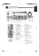
AUDIO/VIDEO CONTROL RECEIVER RECEPTOR DE CONTROL DE AUDIO/VÍDEO RECEPTOR DE COMANDO AUDIO/VÍDEO RX-7001PGD DVD TV/CATV/DBS VCR CD TAPE/MD DVD MUILTI TV/DBS PHONO FM/AM VCR ANALOG/DIGITAL SLEEP SURROUND ON/OFF CENTER 1 2 3 MENU SURROUND TEST REAR-L MODE 4 CD-DISC EFFECT 5 SOUND SEA MODE 6 ENTER REAR-R 7/P 8 0 +10 FM MODE 100+ 10 RETURN 9 SUBWOOFER AUDIO/ TV/VCR MENU CATV/DBS MASTER VOLUME SET RX-7001P AUDIO/VIDEO CONTROL RECEIVER D I G I T A L – TEXT DISPLAY EXIT
Warnings, Cautions and Others / Avisos, precauciones y otras notas / Advertêcias, precauções e outras notas / CAUTION To reduce the risk of electrical shocks, fire, etc.: 1. Do not remove screws, covers or cabinet. 2. Do not expose this appliance to rain or moisture. PRECAUCIÓN Para reducir riesgos de choques eléctricos, incendio, etc.: 1. No extraiga los tornillos, los cubiertas ni la caja. 2. No exponga este aparato a la lluvia o a la humedad.
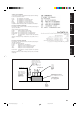
English Caution: Proper Ventilation To avoide risk of electric shock and fire and to protect from damage. Locate the apparatus as follows: Front: No obstructions open spacing. Sides: No obstructions in 10 cm from the sides. Top: No obstructions in 10 cm from the top. Back: No obstructions in 15 cm from the back Bottom: No obstructions, place on the level surface. In addition, maintain the best possible air circulation as illustrated.
English Table of Contents Parts Identification ...................................... 2 Using the DSP Modes ................................ 21 Getting Started ........................................... 3 Available DSP Modes According to the Speaker Arrangement .. 23 Adjusting the 3D-PHONIC Modes .......................................... 24 Adjusting the DAP Modes ....................................................... 24 Adjusting the Surround Modes ................................................
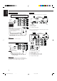
English Parts Identification Become familiar with the buttons and controls on the receiver before use. Refer to the pages in parentheses for details.
English Getting Started This section explains how to connect audio/video components and speakers to the receiver, and how to connect the power supply. Before Installation Connecting the FM and AM Antennas General • Be sure your hands are dry. • Turn the power off to all components. • Read the manuals supplied with the components you are going to connect.
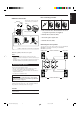
Snap the tabs on the loop into the slots of the base to assemble the AM loop. ANTENNA FM 75 COAXIAL AM Loop Antenna 4 3 2 1 1 1 1 RIG AM LOOP English Basic connecting procedure AM Antenna Connections HT RIG HT RIG HT 1 Cut, twist and remove the insulation at the end of each speaker signal cable (not supplied). AM EXT 2 Turn the knob counterclockwise. 2 1 3 3 Insert the speaker signal cable. 4 Turn the knob clockwise.
English About the speaker impedance Connecting the subwoofer speaker The required speaker impedance of the front speakers does differ depending on whether both the FRONT SPEAKERS 1 and FRONT SPEAKERS 2 terminals are used or only one of them is used. You can enhance the bass by connecting a subwoofer. Connect the input jack of a powered subwoofer to the SUBWOOFER OUT jack on the rear panel, using a cable with RCA pin plugs (not supplied).
RIGHT LEFT AUDIO PHONO CD player CD OUT (REC) To audio output TAPE /MD Video component connections Use the cables with RCA pin plugs (not supplied). Connect the white plug to the audio left jack, the red plug to the audio right jack, and the yellow plug to the video jack. If your video components have S-video (Y/C-separation) terminals, connect them using S-video cables (not supplied).
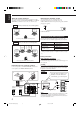
English DVD player TV and/or DBS tuner When connecting the TV, DO NOT connect the TV’s video output to these video input terminals.
Notes: This receiver is equipped with three DIGITAL IN terminals — one digital coaxial terminal and two digital optical terminals, and one DIGITAL OUT terminal. You can connect any digital equipment such as — • DBS tuner, • Digital TV broadcast tuner, • DVD player, • CD player, • and MD recorder. • When shipped from the factory, the DIGITAL IN terminals have been set for use with the following components.
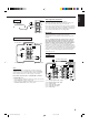
English Connecting the Power Cord Before plugging the receiver into an AC outlet, make sure that all connections have been made. Putting Batteries in the Remote Control Before using the remote control, put two supplied batteries first. When using the remote control, aim the remote control directly at the remote sensor on the receiver. Plug the power cord into an AC outlet. Keep the power cord away from the connecting cables and the antenna. The power cord may cause noise or screen interference.
English Basic Operations The following operations are commonly used when you play any sound source. From the remote control: Press one of the source selecting buttons. IMPORTANT: When using the remote control, check to see if its remote control mode selector is set to the correct position: To operate this receiver, set it to “AUDIO/TV/ VCR.
English Signal and speaker indicators on the display • The signal indicators light up to indicate the incoming channel signals. – Only the indicators for the incoming signals light up. • The frame of the signal indicator (except for “LFE” and “S”) lights up if the corresponding speaker is set to “LARGE” or “SMALL” (for subwoofer, “YES”). – The frames of “L” and “R” indicators always light up.
HEADPHONE mode: This mode can reproduce the LFE channel signals, mixing them with the front channel signals. So you will not miss the subwoofer sounds even if you listen to a source using the headphones. Notes: • While in the HEADPHONE mode, you cannot use any other DSP modes (see page 21.) • Activating the speaker cancels the headphones mode and turns on the DSP mode previously selected.
English Basic Settings Some of the following settings are required after connecting and positioning your speakers in your listening room, while others will make operations easier. IMPORTANT: When using the remote control, check to see if its remote control mode selector is set to the correct position: To operate this receiver, set it to “AUDIO/TV/ VCR.” AUDIO/ TV/VCR CATV/DBS Recording a Source 2. Turn MULTI JOG to adjust the balance.
English 3. Repeat steps 1 and 2 to select the appropriate items for the other speakers. Setting the Subwoofer Information Register whether or not you have connected a subwoofer. Notes: Before you start, remember... • There is a time limit in doing the following steps. If the setting is canceled before you finish, start from step 1 again. On the front panel ONLY: SETTING 1. Press SETTING repeatedly until “SUBWOOFER” appears on the display.
English 2. Turn MULTI JOG to select the delay time of the rear speaker output. MULTI JOG • Turn it clockwise to increase the delay time from 0 msec (“R. DELAY: 0ms”) to 15 msec (“R. DELAY: 15ms”). • Turn it counterclockwise to decrease the delay time from 15 msec (“R. DELAY: 15ms”) to 0 msec (“R. DELAY: 0ms”). Notes: • Rear delay time setting is not valid for the DVD MULTI playback mode. • You cannot adjust the rear delay time when you have set “REAR SPK” to “NONE.
When you use the digital input terminals, you have to register what components are connected to which terminals (DIGITAL IN 1/2/3). Before you start, remember... • There is a time limit in doing the following steps. If the setting is canceled before you finish, start from step 1 again. On the front panel ONLY: 1. Press SETTING repeatedly until “DIGITAL IN” appears on the display. SETTING The display changes to show the current setting. 1.
English Showing the Text Information on the Display When you have connected an MD recorder or CD player equipped with TEXT COMPU LINK remote control system (see page 36), you can show the text information, such as disc title or track title, on the display of this receiver. To show it on the display, follow the procedure below. Before you start, remember... • There is a time limit in doing the following steps. If the setting is canceled before you finish, start from step 1 again.
English Receiving Radio Broadcasts You can browse through all the stations or use the preset function to go immediately to a particular station. IMPORTANT: Using Preset Tuning When using the remote control, check to see if its remote control mode selector is set to the correct position: To operate this receiver, set it to “AUDIO/TV/ VCR.” AUDIO/ TV/VCR Once a station is assigned to a channel number, the station can be quickly tuned. You can preset up to 30 FM and 15 AM stations.
English To tune in a preset station Note: On the front panel: When using the FM MODE button on the remote control, be sure that the 10 keys are activated for the tuner, not for the CD and others. (See page 43.) 1. Turn SOURCE SELECTOR to select the band (FM or AM). SOURCE SELECTOR The last received station of the selected band is tuned in. Assigning Names to Preset Stations TUNER PRESET 2. Press TUNER PRESET. You can assign a name of up to four characters to each preset station.
English Using the SEA Modes The SEA (Sound Effect Amplifier) modes give you control of the way your music sounds. IMPORTANT: Creating Your Own SEA Mode When using the remote control, check to see if its remote control mode selector is set to the correct position: To operate this receiver, set it to “AUDIO/TV/ VCR.” AUDIO/ TV/VCR CATV/DBS You can adjust and store your own SEA adjustment into memory (SEA USERMODE). Before you start, remember... • There is a time limit in doing the following steps.
English Using the DSP Modes The built-in Surround Processor provides three types of the DSP (Digital Signal Processor) mode — 3D-PHONIC mode, DAP (Digital Acoustic Processor) mode and Surround mode. 3D-PHONIC modes DAP modes The 3D-PHONIC mode gives you such a nearly surround effect as is reproduced through the Dolby Surround decoder, which is widely used to reproduce sounds with a feeling of movement like those experienced in movie theaters.
With this receiver, you can use four types of the Surround mode. Following modes cannot be used when only the front speakers are connected to this receiver (without the rear speakers or center speaker). JVC Theater Surround In order to reproduce a more realistic sound field in your listening room while playing soundtracks of software encoded with Dolby DOLBY SURROUND ) you can use JVC Surround (bearing the mark Theater Surround.
English Available DSP Modes According to the Speaker Arrangement Available DSP modes will vary depending on how many speakers are used with this receiver. Make sure that you have set the speaker information correctly (see page 14).
3. Press EFFECT to select an effect level you want. When using the remote control, check to see if its remote control mode selector is set to the correct position: To operate this receiver, set it to “AUDIO/TV/ VCR.
English 3. Adjust the effect level. 1) Press (BALANCE/) SURROUND ADJUST repeatedly until “DSP EFFECT” appears on the display. The display changes to show the current setting. 2) Turn MULTI JOG to select the effect level. • As you turn it, the effect level changes as follows: DSP EFFECT 1 DSP EFFECT 2 DSP EFFECT 5 BALANCE/SURROUND ADJUST Once you have adjusted the Surround modes, the adjustment is memorized for each Surround mode.
• To adjust the center speaker level, press CENTER –/+ (from –10 dB to +10 dB). • To adjust the left rear speaker level, press REAR•L –/+ (from –10 dB to +10 dB). • To adjust the right rear speaker level, press REAR•R –/+ (from –10 dB to +10 dB). CENTER 2 REAR•L 3 5 MENU REAR•R 6 8 9 ENTER Before you start, remember... • Make sure that you have set the speaker information correctly (see page 14). • There is a time limit in doing the following steps.
English TEST 5. Press TEST again to stop the test tone. 4 6. Press EFFECT to select an effect level you want. EFFECT 7/P • Each time you press the button, the effect level changes as follows: DSP EFFECT 1 DSP EFFECT 2 DSP EFFECT 5 DSP EFFECT 3 DSP EFFECT 4 As the number increases, JVC Theater Surround becomes stronger. On the front panel: You can also use the buttons on the front panel to adjust the Surround modes. However, no test tone is available when using the buttons on the front panel.
English For the other DSP modes ––––––––––––––– MEMO ––––––––––––––– On the front panel: 1. Press DSP MODE repeatedly until the mode you want appears on the display. DSP MODE Use this column to write down your DSP mode adjustments for your future reference. • Each time you press the button, the DSP modes change. (See page 23 for more details.) 2. Select and play a sound source.
English Using the DVD MULTI Playback Mode This receiver provides the DVD MULTI playback mode for reproducing the analog discrete output mode of the DVD player. Before playing back a DVD, refer also to the manual supplied with the DVD player. From the remote control: IMPORTANT: When using the remote control, check to see if its remote control mode selector is set to the correct position: To operate this receiver, set it to “AUDIO/TV/ VCR.” 1. Press DVD MULTI so that “DVD MULTI” appears on the display.
You can use the Menus on the TV screen to control the receiver. To use this function, you need to connect the TV to the MONITOR OUT jack on the rear panel (see page 7), and set the TV’s input mode to the proper position to which the receiver is connected. • When the TV’s input mode is incorrect; for example, a different video input or TV tuner mode is selected, you cannot show the Menus on the TV screen.
English Adjusting the Front Speaker Output Balance (Also see page 13) 1. Press MENU. Adjusting the Subwoofer Output Level (Also see page 12) 1. Press MENU. The MAIN MENU appears on the TV. • Pressing one of the % / fi / @ / # buttons also displays the MAIN MENU. 2. Press % / fi to move to “SOUND CONTROL,” then press @ / #. The SOUND CONTROL menu appears. The MAIN MENU appears on the TV. • Pressing one of the % / fi / @ / # buttons also displays the MAIN MENU. 2.
6. Press % / fi to move to the item you want to set or adjust, then press @ / #. On this adjustment menu, you can do the following: “CENTER LEVEL”: Adjust the center speaker output level. “REAR L LEVEL”: Adjust the left rear speaker output level. “REAR R LEVEL”: Adjust the right rear speaker output level. 7. When you finish, press EXIT repeatedly until the menu disappears from the TV. Selecting Your Favorite SEA Mode (Also see page 20) 1. Press MENU. The MAIN MENU appears on the TV.
English 4. Press % / fi to move to “SEA ADJUST.” The SEA ADJUST menu appears. 5. Press % / fi / @ / # to adjust the SEA mode as you want. @ / # : Select the frequency ranges. % / fi : Adjust the frequency levels. 6. Press SET to store the setting into the SEA USERMODE. • If you press EXIT, without pressing SET in this step, you can return to the SEA menu. (The adjustment you have made is active but not stored.) 7. When you finish, press EXIT repeatedly until the menu disappears from the TV. “LFE ATT.
1. Press MENU. The MAIN MENU appears on the TV. • Pressing one of the % / fi / @ / # buttons also displays the MAIN MENU. 2. Press % / fi to move to “TUNER CONTROL,” then press @ / #. The TUNER CONTROL menu appears. 3. Tune into a station on the TUNER CONTROL menu, referring to “Operating the Tuner” on the previous page. 4. Press % / fi to move to “PRESET MEMORY,” then press @ / #. English Storing the Preset Stations (Also see page 18) 6. Press % / fi to move to “PRESET NAME,” then press SET.
English COMPU LINK Remote Control System The COMPU LINK remote control system allows you to operate JVC audio components through the remote sensor on the receiver. To use this remote control system, you need to connect JVC audio components through the COMPU LINK-3 (SYNCHRO) jacks (see below) in addition to the connections using cables with RCA pin plugs (see pages 5 and 6). • Make sure that the AC power cords of these components are unplugged before connection.
The TEXT COMPU LINK remote control system has been newly developed to deal with the disc information recorded in the CD Text * and MDs. Using these information in the discs, you can operate the CD player or MD recorder equipped with the TEXT COMPU LINK remote control system through the receiver. CONNECTIONS: FUNCTIONS: To use this remote control system, you need to connect the CD player and/or MD recorder you want to operate, following the procedures below. 1.
English OPERATIONS To use this remote control system, you need to connect the TV to the MONITOR OUT jack on the rear panel (see page 7), and set the TV’s input mode to the proper position to which the receiver is connected. Make sure you have connected the CD player or MD recorder equipped with the TEXT COMPU LINK remote control system. If not, you cannot use the following functions.
Search for a disc by its performer: 1. Press TEXT DISPLAY while “CD” is selected as the source. The Disc Information screen appears on the TV. 2. Press % / fi to move to “SEARCH,” then press SET. The DISC SEARCH screen appears . 3. Press % / fi to move to “PERFORMER”, then press SET. The PERFORMER SEARCH screen appears. 4. Press % / fi / @ / # to move in front of the first character of the performer you want to search, then press SET.
English Search for a disc by its genre: 1. Press TEXT DISPLAY while “CD” is selected as the source. The Disc Information screen appears on the TV. 2. Press % / fi to move to “SEARCH,” then press SET. The DISC SEARCH screen appears. 3. Press % / fi to move to “GENRE”, then press SET. The GENRE SEARCH screen appears. 4. Press % / fi to move to the genre you want to search, then press SET. To show the unseen genres, press % / fi until they appear.
To insert a space, press % / fi to / @ / # to move , then press SET. To correct an incorrect character: 1) Press % / fi / @ / # to move to + or =, then press SET until the incorrect character is selected. 2) Press % / fi / @ / # to move to , then press SET to erase the character. in front of the correct 3) Press % / fi / @ / # to move character, then press SET to enter the correct character. 5. Press % / fi / @ / # to to “DISC 1: move MICHAEL (in this example),” then press SET.
English AV COMPU LINK Remote Control System The AV COMPU LINK remote control system allows you to operate JVC video components (TV, VCR, and DVD player) through the receiver. To use this remote control system, you need to connect the video components you want to operate, following the diagrams below and the procedure on the next page. TV CONNECTIONS 1: VCR CAUTION: The AV COMPU LINK remote control system cannot control the DBS tuner connected to the TV SOUND/DBS jacks.
2. Connect your VCR, DVD player, TV, and this receiver, using the cables with the monaural miniplugs (not supplied). • See “CONNECTIONS 1” on the previous page. 3. Connect the audio input/output jacks on VCR, DVD player, TV, and this receiver using the cables with RCA pin plug. One-Touch DVD Play Simply by starting playback on the DVD player, you can enjoy the DVD playback without setting other switches manually.
English Operating JVC’s Audio/Video Components You can operate JVC’s audio and video components with this receiver’s remote control, since control signals for JVC components are preset in the remote control. Operating Audio Components IMPORTANT: To operate JVC’s audio components using this remote control: • You need to connect JVC audio components through the COMPU LINK-3 (SYNCHRO) jacks (see page 35) in addition to the connections using cables with RCA pin plugs (see pages 5 and 6).
After pressing CD-DISC (with the remote control mode selector set to “AUDIO/TV/VCR”), you can perform the following operations on a CD player-changer: PLAY: 4: ¢: STOP: PAUSE: 1 – 6, 7/P: Starts playing. Returns to the beginning of the current (or previous) track. Skips to the beginning of the next track. Stops playing. Pauses playing. To release it, press PLAY. Selects the number of a disc installed in a CD player-changer.
English Operating Video Components You can always perform the following operations (with the remote control mode selector set to “AUDIO/TV/VCR”): IMPORTANT: To operate JVC’s video components using this remote control: • You need to connect JVC video components through the AV COMPU LINK terminals (see page 41) in addition to the connections using cables with RCA pin plugs (see pages 6 and 7). • Some JVC VCRs can accept two types of the control signals — remote code “A” and “B.
This remote control supplied with the receiver can transmit control signals for other manufacturers’ VCRs, TVs, CATV converters and DBS tuners. By changing the transmittable signals from preset ones to the other manufacturers’, you can operate the other manufacturer’s components using this remote control. When operating the other manufacturers’ components, refer also to the manuals supplied with them.
English To change the transmittable signals for operating a CATV converter or DBS tuner To change the transmittable signals for operating another manufacturer’s VCR 1. Set the remote control mode to “CATV/DBS.” 1. Set the remote control mode to “AUDIO/TV/ VCR.” 2. Press and hold TV/CATV/DBS . 3. Press TV/DBS. 4. Enter manufacturer’s code (three digits) using buttons 1 – 9, and 0. . 2. Press and hold VCR 3. Press VCR. 4. Enter manufacturer’s code (three digits) using buttons 1 – 9, and 0.
A-Mark Acura Admiral Aiko Akai Akura Alaron Alba Amstrad Anam Anam National Anitech AOC Arcam Archer Audinac Audiosonic Audiovox Basic Line Baur Bell & Howell Beon Blaupunkt Britannia Broksonic Bush Candle Carnivale Carrefour Carver Cascade Cathay CCE Celebrity Centurion Cimline Cineral Citizen Clarivox Contec Continental Edison Craig Crosley Crown CS Electronics Curtis Mathes Daewoo Dansai Dayton De Graaf Decca Denon Dixi ECE Ectec Electroband Electrohome Elin Elta Emerson Envision Erres Etron Ferguson Fid
English Mivar Motorola MTC Multitech NAD National NEC Neckermann NEI Nicamagic Nikkai Nikko Nisato Nordmende NTC Optimus Optonica Orion Osaki Otto Versand Panama Panasonic Pathe Cinema Pausa Penney Philco Philips Phonola Pilot Pioneer Portland Profex Proscan Protech Proton Quasar Quelle Questa R-Line Radio Shack Radiola Rank Arena RCA Realistic Revox Rex Rhapsody Roadstar Runco Saisho Sampo Samsung Samsux Sandra Sansei Sanyo SBR Schneider Scotch Scott Sears SEG Semp Sentra Sharp Siemens Silver 216 093 030
English Manufacturers’ codes for DBS tuner Cyrus Dae Young DNT DX Antenna Kathrein Marantz Panasonic Pantech Philips Radiola RFT Samsung Sony Toshiba Ventana 200 735 200 752 200 200 739 747 200 200 200 773 661 486 200 Manufacturers’ codes for VCR Admiral Adventura Aiko Aiwa Akai Akiba Alba Ambassador Amstrad Anam Anam National Anitech ASA Asha Asuka Audiovox Baird Basic Line Beaumark Bell & Howell Blaupunkt Brandt Brandt Electronic Bush Calix Capehart Carver Catron CCE CGE Cimline Cineral Citizen Clatron
English Melectronic Memorex Memphis Metz MGA MGN Technology Minerva Minolta Mitsubishi Motorola MTC Multitech Murphy NAD National NEC Neckermann Nesco Nikko Nikon Noblex Nokia Nordmende Oceanic Olympus Optimus Optonica Osaki Otto Versand Palladium Panasonic Pathe Marconi Penney Pentax Perdio Philco Philips Phonola Pilot Pioneer Portland Profitronic Proline Protec Pye Quarter Quartz Quasar Quelle Radio Shack Radiola Radix Randex RCA Realistic Rex Ricoh Roadstar Saba Salora Samsung Sanky Sansui Sanyo SBR Sch
Use this chart to help you solve daily operational problems. If there is any problem you cannot solve, contact your JVC service center. PROBLEM POSSIBLE CAUSE SOLUTION The display does not light up. The power cord is not plugged in. Plug the power cord into an AC outlet. No sound from speakers. Speaker signal cables are not connected. Check speaker wiring and reconnect if necessary. The SPEAKERS 1 and 2 buttons are not set correctly. Press SPEAKERS 1 and 2 correctly.
English Specifications Amplifier Output Power At Stereo operation: Front channels: 100 W* per channel, min. RMS, both channels driven into 8 Ω at 1 kHz with no more than 0.9% total harmonic distortion. (IEC268-3/DIN) At Surround operation: Front channels: 100 W* per channel, min. RMS, driven into 8 Ω at 1 kHz with no more than 0.8% total harmonic distortion. Center channel: 100 W*, min. RMS, driven into 8 Ω at 1 kHz, with no more than 0.8% total harmonic distortion.
English FM tuner (IHF) Tuning Range: 87.50 MHz to 108.00 MHz Usable Sensitivity: Monaural: 12.8 dBf (1.2 µV/75 Ω) 50 dB Quieting Sensitivity: Monaural: Stereo: 21.3 dBf (3.2 µV/75 Ω) 41.3 dBf (31.5 µV/75 Ω) Signal-to-Noise Ratio (IHF-A weighted): Monaural: Stereo: 78 dB at 85 dBf 73 dB at 85 dBf Total Harmonic Distortion: Monaural: Stereo: 0.4% at 1 kHz 0.
Mains (AC) Line Instruction (not applicable for Europe, U.S.A., Canada, Australia and U.K.) Instrucción sobre la línea de la red (CA) (no aplicable para Europa, EE.UU., Canadá, Australia, ni el Reino Unido) Instrução sobre a tensão da rede eléctrica (CA) (não aplicável para a Europa, os E.U.A.