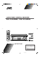
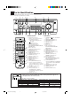
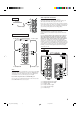
AUDIO/VIDEO CONTROL RECEIVER RX-7010RBK / RX-7012RSL CATV/DBS VCR TV AUDIO DVD DVD MUILTI CD FM/AM VCR TAPE/CDR PHONO + − + TV/DBS − BASS SURROUND DSP ON/OFF MODE BASS BOOST EFFECT 1 TREBLE ANALOG/DIGITAL SLEEP INPUT + CENTER – 2 3 MENU TEST 4 + REAR•L – 5 6 ENTER AUDIO/VIDEO CONTROL RECEIVER – REAR•R + SOUND 7/P 8 9 FM/AM TUNING CATV/DBS CONTROL TV/VIDEO + TUNING − REC PAUSE FM/AM PRESET FM MODE EON – SUB WOOFER + MUTING 10 0 +10 RETURN FM MODE 100+
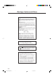
Warnings, Cautions and Others IMPORTANT for the U.K. DO NOT cut off the mains plug from this equipment. If the plug fitted is not suitable for the power points in your home or the cable is too short to reach a power point, then obtain an appropriate safety approved extension lead or consult your dealer. BE SURE to replace the fuse only with an identical approved type, as originally fitted.
SAFETY INSTRUCTIONS “SOME DOS AND DON’TS ON THE SAFE USE OF EQUIPMENT” This equipment has been disigned and manufactured to meet international safety standards but, like any electrical equipment, care must be taken if you are to obtain the best results and safety is to be assured. Do read the operating instructions before you attempt to use the equipment.
Table of Contents Parts Identification ...................................... 2 Getting Started ........................................... 3 Before Installation ...................................................................... 3 Checking the Supplied Accessories ........................................... 3 Connecting the FM and AM (MW/LW) Antennas ..................... 3 Connecting the Speakers ............................................................ 4 Connecting Audio/Video Components ..........
Parts Identification Become familiar with the buttons and controls on the receiver before use. Refer to the pages in parentheses for details.
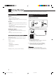
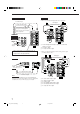
Getting Started This section explains how to connect audio/video components and speakers to the receiver, and how to connect the power supply. Before Installation Connecting the FM and AM (MW/LW) Antennas General • Be sure your hands are dry. • Turn the power off to all components. • Read the manuals supplied with the components you are going to connect. FM Antenna Connections A Locations B A NN TE AN 75 FMAXIAL • Install the receiver in a location that is level and protected from moisture.
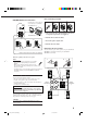
AM (MW/LW) Antenna Connections Snap the tabs on the loop into the slots of the base to assemble the AM (MW/LW) loop. ANTENNA FM 75 COAXIAL Basic connecting procedure 1 1 RIG AM (MW/LW) Loop Antenna AM EXT 1 RIG HT AM LOOP 4 3 2 1 RIG HT HT 1 Cut, twist and remove the insulation at the end of each speaker signal cable (not supplied). 2 Turn the knob counterclockwise. 2 1 3 3 Insert the speaker signal cable. 4 Turn the knob clockwise.
About the speaker impedance Connecting the subwoofer speaker The required speaker impedance of the front speakers does differ depending on whether both the FRONT SPEAKERS 1 and FRONT SPEAKERS 2 terminals are used or only one of them is used. You can enhance the bass by connecting a subwoofer. Connect the input jack of a powered subwoofer to the SUBWOOFER OUT jack on the rear panel, using a cable with RCA pin plugs (not supplied).
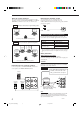
Video component connections CD player Use the cables with RCA pin plugs (not supplied). Connect the white plug to the audio left jack, the red plug to the audio right jack, and the yellow plug to the video jack. If your video components have S-video (Y/C-separation) terminals, connect them using S-video cables (not supplied). Connecting these video components through the S-video input/output terminals will give you better picture playback (or recording) quality.
DVD player TV and/or DBS tuner • When you connect the DVD player with stereo output jacks: To S-video input A B C DVD player To composite video input DVD PHONO Connect the TV to the MONITOR OUT jack to view the playback CD picture from the other connected video components.
Digital connections Notes: This receiver is equipped with four DIGITAL IN terminals — one digital coaxial terminal and three digital optical terminals, and one DIGITAL OUT terminal. You can connect any digital equipment such as — • DBS tuner, • Digital TV broadcast tuner, • DVD player, • CD player, and • CD recorder. • When shipped from the factory, the DIGITAL IN terminals have been set for use with the following components.
Connecting the Power Cord Before plugging the receiver into an AC outlet, make sure that all connections have been made. Putting Batteries in the Remote Control Before using the remote control, put two supplied batteries first. When using the remote control, aim the remote control directly at the remote sensor on the receiver. Plug the power cord into an AC outlet. Keep the power cord away from the connecting cables and the antenna. The power cord may cause noise or screen interference.
Basic Operations The following operations are commonly used when you play any sound source. Turning the Power On and Off (Standby) On the front panel: To turn on the power, press STANDBY/ON . The STANDBY lamp goes off. The name of the current source (or station frequency) appears on the display. STANDBY STANDBY/ON Current source name appears SPK 1 L ANALOG R VOLUME Current volume level is shown here To turn off the power (into standby mode), press STANDBY/ON again. The STANDBY lamp lights up.
Selecting different sources for picture and sound You can watch picture from a video component while listening to sound from another component. Selecting the Front Speakers On the front panel ONLY: When you have connected two pairs of the front speakers, you can select which to use. Press one of the audio source selecting buttons — PHONO, CD, TAPE/CDR, FM/AM, TV SOUND/DBS* (or TV/DBS on the remote control), while viewing the picture from a video component such as the VCR, DVD player, or DBS tuner, etc.
Muting the Sound From the remote control: From the remote control ONLY: Press MUTING to mute the sound through all speakers and headphones connected. MUTING “MUTING” appears on the display and the volume turns off (the volume level indicator goes off). Press BASS +/– or TREBLE +/– to adjust the bass or treble sound level (+10 dB to –10 dB). − BASS − TREBLE + + Attenuating the Input Signal To restore the sound, press MUTING again so that “OFF” appears on the display.
Basic Settings Some of the following settings are required after connecting and positioning your speakers in your listening room, while others will make operations easier. Recording a Source Changing the Source Name For analog-to-analog recording You can record any analog source through the receiver to — • the cassette deck (or CD recorder) connected to the TAPE/CDR jacks, and • the VCR connected to the VCR jacks — at the same time.
Setting the Subwoofer Information 3. Repeat steps 1 and 2 to select the appropriate items for the other speakers. Register whether you have connected a subwoofer or not. Notes: Before you start, remember.... • There is a time limit in doing the following steps. If the setting is canceled before you finish, start from step 1 again. On the front panel ONLY: 1. Press SETTING repeatedly until “SUBWOOFER” appears on the display. T SETTING The display changes to show the current setting. 2.
2. Press CONTROL UP 5/DOWN ∞ to select the delay time of the rear speaker output. CONTROL DOWN UP Low Frequency Effect Attenuator Setting If the bass sound is distorted while playing back a source using Dolby Digital or DTS Digital Surround, follow the procedure below. • Press CONTROL UP 5 to increase the delay time from 0 msec (“R_DELAY 0MS”) to 15 msec (“R_DELAY 15MS”). • Press CONTROL DOWN ∞ to decrease the delay time from 15 msec (“R_DELAY 15MS”) to 0 msec (“R_DELAY 0MS”).
Digital Input (DIGITAL IN) Terminal Setting When you use the digital input terminals, you have to register what components are connected to which terminals (DIGITAL IN 1/2/3/4). Before you start, remember.... • There is a time limit in doing the following steps. If the setting is canceled before you finish, start from step 1 again. On the front panel ONLY: To set the DIGITAL 1 terminal 1. Press SETTING repeatedly until “COAX DIG IN” appears on the display.
When playing a software encoded with the DTS Digital Surround, “AUTO” may not work properly and the following symptoms may occur: • Sound does not come out at the beginning of playback. • Noise comes out while using the searching or skipping function. In this case, press CONTROL UP 5/ DOWN ∞ to select “DTS” while “AUTO” is lit on the display.
Receiving Radio Broadcasts You can browse through all the stations or use the preset function to go immediately to a particular station. Tuning in Stations Manually Using Preset Tuning On the front panel: 1. Press FM/AM to select the band (FM or AM — MW/LW). FM/AM The last received station of the selected band is tuned in. • Each time you press the button, the band alternates between FM and AM (MW/LW). Once a station is assigned to a channel number, the station can be quickly tuned.
Selecting the FM Reception Mode To tune in a preset station On the front panel: 1. Press FM/AM to select the band (FM or AM — MW/LW). When an FM stereo broadcast is hard to receive or noisy FM/AM You can change the FM reception mode while receiving an FM broadcast. • You can store the FM reception mode for each preset station. The last received station of the selected band is tuned in. 2. Press FM/AM PRESET 5/ ∞ until you find the channel you want.
Using the RDS (Radio Data System) to Receive FM Stations RDS allows FM stations to send an additional signal along with their regular program signals. For example, the stations send their station names, as well as information about what type of program they broadcast, such as sports or music, etc. When tuned to an FM station which provides the RDS service, the RDS indicator lights up on the display. With the receiver, you can receive the following types of RDS signals.
From the remote control: 1. Press PTY SEARCH while listening to an FM station. PAUSE PTY SEARCH “PTY SELECT” flashes on the display. 2. Press and hold PTY + or PTY – until the PTY code you want appears on the display, while “PTY SELECT” is flashing. FF/ PTY+ /REW The display gives you the PTY codes described below. PTY– 3. Press PTY SEARCH again, while the PTY code selected in the previous step is still on the display.
CASE 1 If there is no station broadcasting the program you have selected The receiver continues playing the current source (all sources except AM — MW/LW). ‘ When a station starts broadcasting the program you have selected, the receiver automatically switches to the station. The indicator of received PTY code starts flashing. ‘ When the program is over, the receiver goes back to the previously selected source, but still remains in EON standby mode.
Using the DSP Modes The built-in Surround Processor provides two types of the DSP (Digital Signal Processor) mode — Surround mode and DAP (Digital Acoustic Processor) mode. What are the DSP Modes? Surround modes With this receiver, you can use three types of the Surround mode. Following modes cannot be used when only the front speakers are connected to this receiver (without the rear speakers or center speaker).
Reproducing the Sound Field DAP modes In order to reproduce a more acoustic sound field in your listening room while playing soundtracks of stereo sources, you can use DAP modes. This mode can be used when the front speakers and the rear speakers are connected to this receiver (without respect to the center speaker connection). You can select one of the following to your preference.
Available DSP Modes According to the Speaker Arrangement Available DSP modes will vary depending on how many speakers are used with this receiver. Make sure that you have set the speaker information correctly (see page 14).
Adjusting the Surround Modes 5. Adjust the speaker output levels. Once you have adjusted the Surround modes, the adjustment is memorized for each Surround mode. Dolby and DTS Surround adjustments Before you start, remember... • Make sure that you have set the speaker information correctly (see page 14). • There is a time limit in doing the following steps. If the setting is canceled before you finish, start from step 3 again.
JVC Theater Surround adjustments TEST 5. Press TEST again to stop the test tone. Before you start, remember... • Make sure that you have set the speaker information correctly (see page 14). • There is a time limit in doing the following steps. If the setting is canceled before you finish, start from step 2 again. • You cannot adjust the rear speaker output levels when you have set “REAR SPK” to “NO.” See page 14. • You cannot adjust the center speaker output level when you have set “CENTER SPK” to “NO.
From the remote control: Adjusting the DAP Modes Once you have adjusted the DAP modes, the adjustment is memorized for each DAP mode. Before you start, remember... • Make sure that you have set the speaker information correctly (see page 14). • There is a time limit in doing the following steps. If the setting is canceled before you finish, start from step 1 again. • You cannot adjust the rear speaker output level when you have set “REAR SPK” to “NO.” See page 14. 1.
Activating the DSP Modes For the other DSP modes You can use only one DSP mode at a time. When a DSP mode is activated, another DSP mode is canceled if in use. For Dolby Pro Logic, Dolby Digital, and DTS Digital Surround 1. Press DSP MODE repeatedly until the mode you want appears on the display. • Each time you press the button, the DSP modes change. (See page 25 for more details.) DSP MODE 1. Press SURROUND ON/OFF.
Using the DVD MULTI Playback Mode This receiver provides the DVD MULTI playback mode for reproducing the analog discrete output mode of the DVD player. Before playing back a DVD, refer also to the manual supplied with the DVD player. Activating the DVD MULTI Playback Mode You can adjust the DVD MULTI playback mode while playing back a DVD using the analog discrete output mode on the DVD player. Once you have made adjustments, the receiver memorizes the adjustments until you change them.
COMPU LINK Remote Control System The COMPU LINK remote control system allows you to operate JVC audio components through the remote sensor on the receiver. To use this remote control system, you need to connect JVC audio components through the COMPU LINK (SYNCHRO) jacks (see below) in addition to the connections using cables with RCA pin plugs (see pages 5 and 6). • Make sure that the AC power cords of these components are unplugged before connection.
Operating JVC’s Audio/Video Components You can operate JVC’s audio and video components with this receiver’s remote control, since control signals for JVC components are preset in the remote control.
CD changer Cassette deck After pressing CONTROL repeatedly until “CDDSC” appears on the display window, you can perform the following operations on the CD changer: After pressing TAPE/CDR (or CONTROL repeatedly until “TAPE” appears on the display window), you can perform the following operations on a cassette deck: PLAY3: 4: PLAY3: REW: FF: STOP7: PAUSE8: REC PAUSE: ¢: STOP7: PAUSE8: 1 – 6, 7/P: Starts playing. Returns to the beginning of the current (or previous) track.
Operating Video Components VCR You can always perform the following operations: VCR IMPORTANT: To operate JVC’s video components using this remote control: • Some JVC VCRs can accept two types of the control signals — remote code “A” and “B.” Before using this remote control, make sure that the remote control code of the VCR connected to the VCR jacks is set to code “A.
Operating Other Manufacturers’ Video Equipment This remote control supplied with the receiver can transmit control signals for other manufacturers’ VCRs, TVs, CATV converters, DBS tuners, and DVD players. By changing the transmittable signals from preset ones to the other manufacturers’, you can operate the other manufacturer’s components using this remote control. When operating the other manufacturers’ components, refer also to the manuals supplied with them.
To change the transmittable signals for operating a CATV converter or DBS tuner 1. Press and hold CATV/DBS . 2. Press CATV/DBS CONTROL. 3. Enter manufacturer’s code using buttons 1–9, and 0. See the list to the right to find the code. 4. Release CATV/DBS . The following buttons can be used for operating the CATV converter or DBS tuner: CATV/DBS : Turns on and off the CATV converter or DBS tuner. CH +/–: Changes the channels. 1 – 10, 0, 100+ (+10): Selects the channels.
To change the transmittable signals for operating another manufacturer’s VCR 1. Press and hold VCR Manufacturer . 2. Press VCR. 3. Enter manufacturer’s code using buttons 1–9, and 0. See the list to the right to find the code. 4. Release VCR . The following button can be used for operating the VCR: VCR : Turns on and off the VCR. After pressing VCR, you can perform the following operations on the VCR: CH +/–: Changes the TV channels on the VCR. 1 – 10, 0, 100+ (+10): Selects the TV channels.
To change the transmittable signals for operating another manufacturer’s DVD player 1. Press and hold AUDIO . Manufacturer 2. Press DVD. 3. Enter manufacturer’s code using buttons 1–9, and 0. See the list to the right to find the code. 4. Release AUDIO . After pressing DVD or DVD MULTI, you can perform the following operations on a DVD player: PLAY3: 4: ¢: STOP7: PAUSE8: Starts playing. Returns to the beginning of the current (or previous) tracks. Skips to the beginning of the next track.
Troubleshooting Use this chart to help you solve daily operational problems. If there is any problem you cannot solve, contact your JVC service center. PROBLEM SOLUTION POSSIBLE CAUSE The display does not light up. The power cord is not plugged in. Plug the power cord into an AC outlet. No sound from speakers. Speaker signal cables are not connected. Check speaker wiring and reconnect if necessary. The SPEAKERS ON/OFF 1 and 2 buttons are not set correctly. Press SPEAKERS ON/OFF 1 and 2 correctly.
Specifications Amplifier Output Power At Stereo operation: Front channels:100 W per channel, min. RMS, both channels driven into 8 Ω at 1 kHz with no more than 0.9% total harmonic distortion. (IEC268-3/DIN) At Surround operation: Front channels: 100 W per channel, min. RMS, driven into 8 Ω at 1 kHz with no more than 0.8% total harmonic distortion. Center channel: 100 W, min. RMS, driven into 8 Ω at 1 kHz, with no more than 0.8% total harmonic distortion. Rear channels: 100 W per channel, min.
VICTOR COMPANY OF JAPAN, LIMITED V EN RX-7010&7012R[B]COVER_f J 2 01.1.