AUDIO/VIDEO CONTROL RECEIVER RX-7040B/RX-7042S INSTRUCTIONS For Customer Use: Enter below the Model No. and Serial No. which are located either on the rear, bottom or side of the cabinet. Retain this information for future reference. Model No. Serial No. LVT1170-001B [J] Cover_2_7040[J] 1 04.1.
Warnings, Cautions and Others/ Mises en garde, précautions et indications diverses CAUTION RISK OF ELECTRIC SHOCK DO NOT OPEN CAUTION: TO REDUCE THE RISK OF ELECTRIC SHOCK. DO NOT REMOVE COVER (OR BACK) NO USER SERVICEABLE PARTS INSIDE. REFER SERVICING TO QUALIFIED SERVICE PERSONNEL.
Table of Contents Introduction ................................................ 2 Basic Settings ........................................... 21 Features ...................................................................................... 2 Precautions ................................................................................. 2 Quick Speaker Setup ................................................................ 21 Basic Setting Items ...............................................................
Introduction We would like to thank you for purchasing one of our JVC products. Before operating this unit, read this manual carefully and thoroughly to obtain the best possible performance from your unit, and retain this manual for future reference.
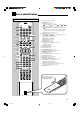
Parts Identification Remote Control See pages in parentheses for details.
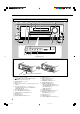
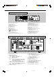
Front Panel 3 2 1 4 5 6 7 8 MASTER VOLUME SURROUND STANDBY DSP STANDBY/ON SPEAKERS ON/OFF SURROUND/ DSP OFF 1 CC CONVERTER 2 DVD MULTI DVD VCR TV SOUND/DBS CD TAPE/CDR FM AM SUBWOOFER OUT ON/OFF SETTING ADJUST ANALOG DIRECT MULTI JOG QUICK SPEAKER SETUP EXIT PUSH – OPEN PUSH SET PHONES 9 p io; q w EX / ES MIDNIGHT MODE INPUT ANALOG INPUT DIGITAL FM/AM TUNING a FM/AM PRESET FM MODE MEMORY TUNER CONTROL INPUT ATT er ty u Inside the front door How to open the fron
Display Window 1 2 DUAL ANALOG DIGITAL AUTO 96/24 C L R S MULTI = ~!@ TUNED STEREO AUTO MUTING ONE TOUCH OPERATION SLEEP LINEAR PCM SUBWFR LFE LS 6789 0 - 3 45 VIRTUAL SB MIDNIGHT MODE PRO LOGIC NEO:6 D. EQ DIGITAL DSP B. BOOST HEADPHONE SPEAKERS 1 2 VOLUME INPUT ATT 3D - PHONIC RS SB # $ % ^& * = ~ ! @ # $ % ^ & * ( ) _ + See pages in parentheses for details.
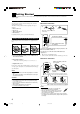
Getting Started This section explains how to connect audio/video components and speakers to the receiver, and how to connect the power supply. Checking the Supplied Accessories Check to be sure you have all of the following items, which are supplied with the receiver. The number in the parentheses indicates quantity of the pieces supplied.
Connecting the Speakers and Subwoofer Speaker connections 1 You can connect the following speakers: • Two pairs of front speakers. • One pair of surround speakers. • One surround back speaker or one pair of surround back speakers. • One center speaker. • One powered subwoofer. • Use only the speakers of the SPEAKER IMPEDANCE indicated by the speaker terminals. – When connecting to either the FRONT SPEAKERS 1 or 2 terminals, use speakers with an impedance of 8 Ω to 16 Ω.
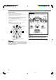
Placing speakers Front speakers (L/R) and center speaker (C) • Place these speakers at the same height from the floor, at or near ear level. • Array across the front of the viewing area. Speaker layout Ideal speaker layout varies depending on the conditions of your listening room. The diagram below is a recommended typical example. Subwoofer Surround speakers (LS/RS) and surround back speakers (SB) • Place these speakers at a position which is 60 cm to 90 cm (2 ft to 3 ft) higher than the listener’s ears.
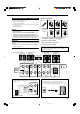
Connecting Audio/Video Components When connecting individual components, refer also to the manuals supplied with them. Cassette deck You can connect either a cassette deck or a CD recorder to the TAPE/CDR jacks. When connecting a CD recorder to the TAPE/CDR jacks, see below. Analog connections If your audio components have digital audio output terminal, connecting them using the digital cords explained in “Digital Connections” (see page 12). By using this terminal, you can get better sound quality.
Video component connections TV and/or DBS tuner Use the cables with RCA pin plugs (not supplied). Connect the white plug to the audio left jack, the red plug to the audio right jack, and the yellow plug to the video jack. • If your video components have S-video (Y/C-separation) and/or component video (Y, PB, PR) terminals, connect them using an Svideo cable (not supplied) and/or component video cable (not supplied).
DVD player To enjoy Dolby Digital and DTS multi-channel software (including Dual Mono software), connect the DVD player through the digital or analog discrete (DVD MULTI) terminals. • When you connect a DVD player with stereo output jacks: COMPONENT VIDEO • When you connect a DVD player with its analog discrete output (5.1-channel reproduction) jacks: This connection is the best connection method for enjoying DVD Audio sounds.
Digital output terminal Digital connections This receiver is equipped with four DIGITAL IN terminals—one digital coaxial terminal and three digital optical terminals—and one DIGITAL OUT (optical) terminal on the rear. You can connect any digital components which have an optical digital input terminal.
Basic Operations The following operations are commonly used when you play any sound sources. Operations hereafter will be explained using the buttons on the front panel. You can also use the buttons on the remote control for the same functions if they have the same and similar names/marks. Selecting the Source to Play Daily Operational Procedure 1 4 3 2 Press one of the source selection buttons.
Speaker and signal indicators on the display By checking the following indicators, you can easily confirm which speakers you are activating and which signals are coming into this receiver. Speaker indicators L C Signal indicators R L C SUBWFR LFE LS S R LFE RS LS SB S Selecting different sources for picture and sound While watching pictures from a video source, you can listen to sound of an audio source.
Selecting the Front Speakers Remote NOT When you have connected two pairs of the front speakers, you can select which to use. To use the speakers connected to the FRONT SPEAKERS 1 terminals, press SPEAKERS ON/OFF 1 so that the SPEAKERS 1 indicator lights up on the display. • Make sure that the SPEAKERS 2 indicator is not lit. To use the speakers connected to the FRONT SPEAKERS 2 terminals, press SPEAKERS ON/OFF 2 so that the SPEAKERS 2 indicator lights up on the display.
2. Press INPUT DIGITAL to select “DGTL AUTO.” • When using the remote control, press ANALOG/DIGITAL INPUT. Each time you press the button, the analog (ANALOG) and digital (DGTL AUTO) input modes alternate. Setting the Dynamic Range You can enjoy a powerful sound at night using Midnight Mode. The DIGITAL AUTO indicator lights up on the display.
Turning Analog Direct On and Off You can enjoy the sound closer to the original source by overriding the sound adjustments such as Midnight Mode (see page 16), Bass Boost (see page 18), Equalization pattern (see page 28), speaker output level adjustments (see page 28), and Surround and DSP modes (see pages 30 to 35). You can only adjust the volume level and the subwoofer output level while Analog Direct is in use. • Once you have made an adjustment, it is memorized for each analog source.
The following basic operations are possible only using the remote control. Using the Sleep Timer Using the Sleep Timer, you can fall asleep while listening to music. When the shut-off time comes, the receiver turns off automatically. Changing the Display Brightness AUDIO Press SLEEP repeatedly.
Receiving Radio Broadcasts You can browse through all the stations or use the preset function to go immediately to a particular station. Using Preset Tuning Tuning in to Stations Manually 1. Press FM or AM to select the band. Once a station is assigned to a channel number, the station can be quickly tuned in. You can preset up to 30 FM and 15 AM stations. The last received station of the selected band is tuned in. ANALOG L R TUNED STEREO AUTO MUTING LINEAR PCM SPEAKERS 1 VOLUME 2.
To tune in to a preset station Selecting the FM Reception Mode On the front panel: 1. Press FM or AM to select the band. The last received station of the selected band is tuned in. 2. Press FM/AM PRESET 5 or ∞ until you find the channel you want. • Pressing FM/AM PRESET 5 increases the number. • Pressing FM/AM PRESET ∞ decreases the number. When an FM stereo broadcast is hard to receive or noisy, you can change the FM reception mode while receiving an FM broadcast.
Basic Settings Some of the following settings are required after connecting and positioning your speakers while others will make operations easier. You can use QUICK SPEAKER SETUP to easily set up your speaker configuration. Quick Speaker Setup Remote NOT Quick Speaker Setup helps you to easily and quickly register the speaker size and speaker distance according to your listening room to create the best possible surround effect. • You can also register each speaker’s information manually.
Speakers (channels) number and the size You can find how each of the speaker size is defined according to the number of connected speakers (speaker channel “CH” number) you select. • Subwoofer is counted as 0.1 channel. The size of connected speakers CH L/R C LS/RS SB SUBWFR 2.0CH LARGE NONE NONE NONE NO 2.1CH SMALL NONE NONE NONE YES 3.0CH LARGE SMALL NONE NONE NO 3.1CH SMALL SMALL NONE NONE YES 4.0CH LARGE NONE SMALL NONE 4.1CH SMALL NONE SMALL 5.
Remote NOT Basic Procedure : shows the initial setting in the following tables. Setting the speakers Before you start, remember... There is a time limit in doing the following steps. If the setting is canceled before you finish, start from step 1 again. 1. Press SETTING. The last selected item appears on the display. VOLUME SUB WOOFER: NO Select when no subwoofer is used. If you have selected “NO” for the subwoofer, you cannot use the SUBWOOFER OUT ON/OFF button on the front panel.
Setting the speaker distance Setting the bass sounds The distance from your listening point to the speakers is another important element to obtain the best possible sound of the Surround and DSP modes. Set the distance from your listening point to the speakers. By referring to the speaker distance setting, this unit automatically sets the delay time of the sound through each speaker so that sounds through all the speakers can reach you at the same time.
7 Low frequency effect attenuator—LFE ATTENUATE If the bass sound is distorted while playing back software encoded with Dolby Digital or DTS, set the LFE level to eliminate distortion. • This function takes effect only when the LFE signals come in. Setting for easy and effective surround operations 7 Auto Surround—AUTO SURROUND Normally select this. Auto Surround works when the unit detects the incoming digital signal. In other words, it works...
7 Digital optical terminals—DGTL IN OPTICAL 7 For the DBS tuner—VIDEO IN DBS Set the components connected to the digital optical terminals (DIGITAL 2 – 4). Select one of the following: • As you turn MULTI JOG, the digital optical input terminals are set to used for following digital components: VIDEO DBS: CMPNT*2 Select when connecting the DBS tuner to the component video input jacks.
Adjusting Sound You can make sound adjustment to your preference after completing basic setting. Basic Adjustment Items Basic Procedure On the following pages, you can adjust the items listed below: • You can adjust only the items applicable to the current sound mode. • If Analog Direct is in use, you cannot make any sound adjustments. Items To do See page EQ 63Hz Adjust equalizer pattern at 63 Hz. 28 EQ250Hz Adjust equalizer pattern at 250 Hz. 28 EQ 1kHz Adjust equalizer pattern at 1 kHz.
Adjusting the equalization patterns Adjusting the speaker output levels You can adjust the equalization patterns to your preference. • Once you have made an adjustment, it is memorized for each source. • The equalization pattern affects the front speaker sounds only. You can adjust the speaker output levels. • Once you have made an adjustment, it is memorized for each source.
For DAP modes and Mono Film • Once you have made an adjustment, it is memorized for each mode. EFFECT ROOMSIZE LIVENESS Adjust the effect level. As the number increases, the effect becomes stronger. (Adjustable range: 1 to 5. “3” is the initial setting, and normally select this.) Adjust the liveness effect. As the number increases, the attenuation level of reflections over time decreases so that acoustics change from “Dead” to “Live.” (Adjustable range: 1 to 5.
Using the Surround Modes This unit activates a variety of Surround modes automatically. The basic settings and adjustments stored (see pages 21 to 29) are applied. Reproducing Theater Ambience In a movie theater, many speakers are located on the walls to reproduce impressive multi-surround sounds, reaching you from all directions. With these many speakers, sound localization and sound movement can be expressed.
Dolby Pro Logic II DTS 96/24 Dolby Pro Logic II is a multi-channel playback format to convert 2-channel software into 5-channel (plus subwoofer). The matrixbased conversion method used for Dolby Pro Logic II makes no limitation for the cutoff frequency of the surround treble and enables stereo surround sound. • This receiver provides two types of Dolby Pro Logic II modes— Pro Logic II Movie (PLII MOVIE) and Pro Logic II Music (PLII MUSIC).
Surround Modes Applicable to the Various Software Available Surround modes vary depending on the speaker settings and the incoming signals. The table below shows the relation of the Surround modes and the incoming signals (with the surround back speakers and EX/ES setting). • The numbers inside the parentheses following the incoming signal type indicate the number of the front channels and that of the surround channels.
Activating the Surround Modes Available Surround modes vary depending on the speaker settings and the incoming signals. (See page 32.) Activating one of the Surround modes for a source automatically recalls the memorized settings and adjustments (see pages 21 to 29). Activating the surround modes automatically You can enjoy the Surround mode simply by selecting the source (with digital input selected for that source) or select the digital input for the selected source.
Using the DSP Modes This unit activates a variety of DSP modes automatically. The basic settings and adjustments stored (see pages 21 to 29) are applied automatically. Reproducing the Sound Field The sound heard in a concert hall, club, etc. consists of direct sound and indirect sound—early reflections and reflections from behind. Direct sounds reach the listener directly without any reflection. On the other hand, indirect sounds are delayed by the distances of the ceiling and walls.
All channel stereo mode This mode can reproduce a larger stereo sound field using all the connected (and activated) speakers. • If the surround speakers are set to “NONE,” you cannot select “ALL STEREO.” Activating the DSP Modes Activating one of the DSP modes for a source automatically recalls the memorized settings and adjustments (see pages 21 to 29.) You can also use the buttons on the remote control for the same functions. 1. Select and play any source excluding DVD MULTI. 2.
Using the DVD MULTI Playback Mode This receiver provides the DVD MULTI playback mode for reproducing the analog discrete output mode of the DVD player. Activating the DVD MULTI Playback Mode Connection diagram COMPONENT VIDEO DVD IN VIDEO AUDIO SUBWOOFER CENTER RIGHT DVD MULTI playback mode is the best connection method for enjoying DVD Audio sounds. • When a DVD Audio disc is played back, the original highquality sounds can be reproduced only using this mode.
COMPU LINK Remote Control System The COMPU LINK remote control system allows you to operate JVC’s audio components through the remote sensor on the receiver. To use this remote control system, you need to connect JVC’s audio components through the COMPU LINK (SYNCHRO) jacks (see below) in addition to the connections using cables with RCA pin plugs (see pages 9). • Make sure that the AC power cords of these components are unplugged before connection.
AV COMPU LINK Remote Control System The AV COMPU LINK remote control system allows you to operate JVC’s video components (TV, VCR, and DVD player) through the receiver. This receiver is equipped with the AV COMPU LINK-III, which adds a function to operate JVC’s video components through the video components terminals. To use this remote control system, connect the video components you want to operate, following the diagrams below and the procedure on the next page.
Connecting procedure 1. If you have already plugged your VCR , DVD player, TV and this receiver into the AC outlets, unplug their AC power cords first. 2. Connect your VCR, DVD player, TV and this receiver, using the cables with the monaural miniplugs (not supplied). • See “CONNECTIONS 1” on the previous page. 3. Connect the audio input/output jacks on VCR, DVD player, TV and this receiver using the cables with RCA pin plugs. • See pages 10 and 11. 4.
Operating JVC’s Audio/Video Components You can operate JVC’s audio and video components with this receiver’s remote control, since control signals for JVC’s components are preset in the remote control.
CD recorder After pressing TAPE/CDR (or TAPE/CDR CONT), you can perform the following operations on a CD recorder: 3: 4: ¢: 7: 8: REC PAUSE: Start playing. Return to the beginning of the current (or previous) track. Skip to the beginning of the next track. Stop playing and recording. Pause playing or recording. To resume, press 3. Enter recording pause. To start recording, press this button then 3.
Operating Other Manufacturers’ Video Equipment This remote control supplied with the receiver can transmit control signals for other manufacturers’ TVs, CATV converters, DBS tuners, VCRs and DVD players. When operating the other manufacturers’ components, refer also to the manuals supplied with them. • After replacing batteries for the remote control, you need to set the manufactures’ codes again. . See the list on page 44 to find the code. 4. Release CATV/DBS 3.
To change the transmittable signals for operating another manufacturer’s VCR To change the transmittable signals for operating another manufacturer’s DVD player 1. Press and hold VCR . 2. Press VCR. 3. Enter manufacturer’s code using buttons 1 – 9, and 0. 1. Press and hold DVD See the list on page 44 to find the code. 4. Release VCR . 5. Try to operate your VCR by pressing VCR . If there are more than one code listed for your brand of VCR, try each one until the correct one is entered.
For TV Manufacturer JVC Akai Bell & Howell Centurion Coronad Daewoo Emerson Fisher GE/Pana GE/RCA Gold Star Hitachi KTV Magnavox Marantz Mitsubishi Codes For VCR Manufacturer 01* 02 03 04 05 06, 07, 08 09, 10, 11, 12, 13 14 15, 16 17 18, 19 20, 21 22, 23 24 25 25 Panasonic Philips Pioneer Proscan Quasar Radioshack RCA Samsung Sanyo Sears Sharp Sony Symphonic Toshiba Zenith Codes 26, 27 24 28 29 30 31 02, 17, 32, 33, 34, 35 36, 37 14 38 39 40 41, 42 38 43, 44 For CATV converter Manufacturer Codes Ge
Troubleshooting Use this chart to help you solve daily operational problems. If there is any problem you cannot solve, contact your JVC’s service center. PROBLEM POSSIBLE CAUSE SOLUTION The display does not light up. The power cord is not plugged in. Plug the power cord into an AC outlet. No sound from speakers. Speaker signal cables are not connected. Check speaker wiring and reconnect if necessary. (See page 7.) The SPEAKERS ON/OFF 1 and SPEAKERS ON/OFF 2 buttons are not set correctly.
Specifications Amplifier Output Power At Stereo Operation Front Channel: 130 W per channel, min. RMS, driven into 8 Ω, 20 Hz to 20 kHz, with no more than 0.08% total harmonic distortion. At Surround Operation Front Channel: 130 W per channel, min. RMS, driven into 8 Ω at 1 kHz, with no more than 0.8% total harmonic distortion. Center Channel: 130 W, min. RMS, driven into 8 Ω at 1 kHz, with no more than 0.8% total harmonic distortion. Surround Channel: 130 W per channel, min.
LIMITED WARRANTY AUDIO-2 JVC COMPANY OF AMERICA warrants this product and all parts thereof, except as set forth below ONLY TO THE ORIGINAL PURCHASER AT RETAIL to be FREE FROM DEFECTIVE MATERIALS AND WORKMANSHIP from the date of original retail purchase for the period as shown below. ("The Warranty Period") PARTS 2 LABOR YRS 2 YRS THIS LIMITED WARRANTY IS VALID ONLY IN THE FIFTY (50) UNITED STATES, THE DISTRICT OF COLUMBIA AND IN COMMONWEALTH OF PUERTO RICO.
Authorized Service Centers ® QUALITY SERVICE HOW TO LOCATE YOUR JVC SERVICE CENTER TOLL FREE: 1 (800) 537-5722 http://www.jvc.com Dear Customer, In order to receive the most satisfaction from your purchase,please read the instruction booklet before operating the unit.In the event that repairs are necessary, please call 1 (800)537-5722 for your nearest authorized servicer or visit our website at www.JVC.com Remember to retain your Bill of Sale for Warranty Service.
RX-7040B/RX-7042S AUDIO/VIDEO CONTROL RECEIVER VICTOR COMPANY OF JAPAN, LIMITED EN © 2004 VICTOR COMPANY OF JAPAN, LIMITED Cover_2_7040[J] 2 0104MWMMDWJEIN 04.1.
English Français AUDIO/VIDEO CONTROL RECEIVER RECEPTEUR DE COMMANDE AUDIO/VIDEO RX-7040B/RX-7042S INSTRUCTIONS MANUEL D’INSTRUCTIONS LVT1170-002A [C] Cover_7040[C] 1 04.2.
Warnings, Cautions and Others/ Mises en garde, précautions et indications diverses CAUTION RISK OF ELECTRIC SHOCK DO NOT OPEN CAUTION: TO REDUCE THE RISK OF ELECTRIC SHOCK. DO NOT REMOVE COVER (OR BACK) NO USER SERVICEABLE PARTS INSIDE. REFER SERVICING TO QUALIFIED SERVICE PERSONNEL.
Introduction ................................................ 2 Basic Settings ........................................... 21 Features ...................................................................................... 2 Precautions ................................................................................. 2 Quick Speaker Setup ................................................................ 21 Basic Setting Items ...................................................................
English Introduction We would like to thank you for purchasing one of our JVC products. Before operating this unit, read this manual carefully and thoroughly to obtain the best possible performance from your unit, and retain this manual for future reference.
English Parts Identification Remote Control See pages in parentheses for details.
English Front Panel 3 2 1 4 5 6 7 8 MASTER VOLUME SURROUND STANDBY DSP STANDBY/ON SPEAKERS ON/OFF SURROUND/ DSP OFF 1 CC CONVERTER 2 DVD MULTI DVD VCR TV SOUND/DBS CD TAPE/CDR FM AM SUBWOOFER OUT ON/OFF SETTING ADJUST ANALOG DIRECT MULTI JOG QUICK SPEAKER SETUP EXIT PUSH – OPEN PUSH SET PHONES 9 p io; q w EX / ES MIDNIGHT MODE INPUT ANALOG INPUT DIGITAL FM/AM TUNING a FM/AM PRESET FM MODE MEMORY TUNER CONTROL INPUT ATT er ty u Inside the front door How to open
English Display Window 1 2 DUAL ANALOG DIGITAL AUTO 96/24 C L R S MULTI = ~!@ TUNED STEREO AUTO MUTING ONE TOUCH OPERATION SLEEP LINEAR PCM SUBWFR LFE LS 6789 0 - 3 45 VIRTUAL SB MIDNIGHT MODE PRO LOGIC NEO:6 D. EQ DIGITAL DSP B. BOOST HEADPHONE SPEAKERS 1 2 VOLUME INPUT ATT 3D - PHONIC RS SB # $ % ^& * = ~ ! @ # $ % ^ & * ( ) _ + See pages in parentheses for details.
English Getting Started This section explains how to connect audio/video components and speakers to the receiver, and how to connect the power supply. Checking the Supplied Accessories Check to be sure you have all of the following items, which are supplied with the receiver. The number in the parentheses indicates quantity of the pieces supplied.
Speaker connections 1 You can connect the following speakers: • Two pairs of front speakers. • One pair of surround speakers. • One surround back speaker or one pair of surround back speakers. • One center speaker. • One powered subwoofer. • Use only the speakers of the SPEAKER IMPEDANCE indicated by the speaker terminals. – When connecting to either the FRONT SPEAKERS 1 or 2 terminals, use speakers with an impedance of 8 Ω to 16 Ω.
English Placing speakers Front speakers (L/R) and center speaker (C) • Place these speakers at the same height from the floor, at or near ear level. • Array across the front of the viewing area. Speaker layout Ideal speaker layout varies depending on the conditions of your listening room. The diagram below is a recommended typical example. Subwoofer Surround speakers (LS/RS) and surround back speakers (SB) • Place these speakers at a position which is 60 cm to 90 cm higher than the listener’s ears.
When connecting individual components, refer also to the manuals supplied with them. English Connecting Audio/Video Components Cassette deck You can connect either a cassette deck or a CD recorder to the TAPE/CDR jacks. When connecting a CD recorder to the TAPE/CDR jacks, see below. Analog connections If your audio components have digital audio output terminal, connecting them using the digital cords explained in “Digital Connections” (see page 12).
English Video component connections TV and/or DBS tuner Use the cables with RCA pin plugs (not supplied). Connect the white plug to the audio left jack, the red plug to the audio right jack, and the yellow plug to the video jack. • If your video components have S-video (Y/C-separation) and/or component video (Y, PB, PR) terminals, connect them using an Svideo cable (not supplied) and/or component video cable (not supplied).
English DVD player To enjoy Dolby Digital and DTS multi-channel software (including Dual Mono software), connect the DVD player through the digital or analog discrete (DVD MULTI) terminals. • When you connect a DVD player with stereo output jacks: COMPONENT VIDEO • When you connect a DVD player with its analog discrete output (5.1-channel reproduction) jacks: This connection is the best connection method for enjoying DVD Audio sounds.
English Digital output terminal Digital connections This receiver is equipped with four DIGITAL IN terminals—one digital coaxial terminal and three digital optical terminals—and one DIGITAL OUT (optical) terminal on the rear. You can connect any digital components which have an optical digital input terminal.
English Basic Operations The following operations are commonly used when you play any sound sources. Operations hereafter will be explained using the buttons on the front panel. You can also use the buttons on the remote control for the same functions if they have the same and similar names/marks. Selecting the Source to Play Daily Operational Procedure 1 4 3 2 Press one of the source selection buttons.
English Speaker and signal indicators on the display By checking the following indicators, you can easily confirm which speakers you are activating and which signals are coming into this receiver. Speaker indicators L C Signal indicators R L C SUBWFR LFE LS S R LFE RS LS SB S Selecting different sources for picture and sound While watching pictures from a video source, you can listen to sound of an audio source.
Remote NOT When you have connected two pairs of the front speakers, you can select which to use. To use the speakers connected to the FRONT SPEAKERS 1 terminals, press SPEAKERS ON/OFF 1 so that the SPEAKERS 1 indicator lights up on the display. • Make sure that the SPEAKERS 2 indicator is not lit. To use the speakers connected to the FRONT SPEAKERS 2 terminals, press SPEAKERS ON/OFF 2 so that the SPEAKERS 2 indicator lights up on the display. • Make sure that the SPEAKERS 1 indicator is not lit.
English 2. Press INPUT DIGITAL to select “DGTL AUTO.” • When using the remote control, press ANALOG/DIGITAL INPUT. Each time you press the button, the analog (ANALOG) and digital (DGTL AUTO) input modes alternate. Setting the Dynamic Range You can enjoy a powerful sound at night using Midnight Mode. The DIGITAL AUTO indicator lights up on the display.
You can enjoy the sound closer to the original source by overriding the sound adjustments such as Midnight Mode (see page 16), Bass Boost (see page 18), Equalization pattern (see page 28), speaker output level adjustments (see page 28), and Surround and DSP modes (see pages 30 to 35). You can only adjust the volume level and the subwoofer output level while Analog Direct is in use. • Once you have made an adjustment, it is memorized for each analog source.
English The following basic operations are possible only using the remote control. Using the Sleep Timer Using the Sleep Timer, you can fall asleep while listening to music. When the shut-off time comes, the receiver turns off automatically. Changing the Display Brightness AUDIO Press SLEEP repeatedly.
English Receiving Radio Broadcasts You can browse through all the stations or use the preset function to go immediately to a particular station. Using Preset Tuning Tuning in to Stations Manually 1. Press FM or AM to select the band. Once a station is assigned to a channel number, the station can be quickly tuned in. You can preset up to 30 FM and 15 AM stations. The last received station of the selected band is tuned in. ANALOG L R TUNED STEREO AUTO MUTING LINEAR PCM SPEAKERS 1 VOLUME 2.
English To tune in to a preset station Selecting the FM Reception Mode On the front panel: 1. Press FM or AM to select the band. The last received station of the selected band is tuned in. 2. Press FM/AM PRESET 5 or ∞ until you find the channel you want. • Pressing FM/AM PRESET 5 increases the number. • Pressing FM/AM PRESET ∞ decreases the number. When an FM stereo broadcast is hard to receive or noisy, you can change the FM reception mode while receiving an FM broadcast.
English Basic Settings Some of the following settings are required after connecting and positioning your speakers while others will make operations easier. You can use QUICK SPEAKER SETUP to easily set up your speaker configuration. Quick Speaker Setup Remote NOT Quick Speaker Setup helps you to easily and quickly register the speaker size and speaker distance according to your listening room to create the best possible surround effect. • You can also register each speaker’s information manually.
English Speakers (channels) number and the size You can find how each of the speaker size is defined according to the number of connected speakers (speaker channel “CH” number) you select. • Subwoofer is counted as 0.1 channel. The size of connected speakers CH L/R C LS/RS SB SUBWFR 2.0CH LARGE NONE NONE NONE NO 2.1CH SMALL NONE NONE NONE YES 3.0CH LARGE SMALL NONE NONE NO 3.1CH SMALL SMALL NONE NONE YES 4.0CH LARGE NONE SMALL NONE 4.1CH SMALL NONE SMALL 5.
English Remote NOT Basic Procedure : shows the initial setting in the following tables. Setting the speakers Before you start, remember... There is a time limit in doing the following steps. If the setting is canceled before you finish, start from step 1 again. 1. Press SETTING. The last selected item appears on the display. VOLUME SUB WOOFER: NO Select when no subwoofer is used. If you have selected “NO” for the subwoofer, you cannot use the SUBWOOFER OUT ON/OFF button on the front panel.
English Setting the speaker distance Setting the bass sounds The distance from your listening point to the speakers is another important element to obtain the best possible sound of the Surround and DSP modes. Set the distance from your listening point to the speakers. By referring to the speaker distance setting, this unit automatically sets the delay time of the sound through each speaker so that sounds through all the speakers can reach you at the same time.
If the bass sound is distorted while playing back software encoded with Dolby Digital or DTS, set the LFE level to eliminate distortion. • This function takes effect only when the LFE signals come in. English 7 Low frequency effect attenuator—LFE ATTENUATE Setting for easy and effective surround operations 7 Auto Surround—AUTO SURROUND Normally select this. Auto Surround works when the unit detects the incoming digital signal. In other words, it works...
English 7 Digital optical terminals—DGTL IN OPTICAL 7 For the DBS tuner—VIDEO IN DBS Set the components connected to the digital optical terminals (DIGITAL 2 – 4). Select one of the following: • As you turn MULTI JOG, the digital optical input terminals are set to used for following digital components: VIDEO DBS: CMPNT*2 Select when connecting the DBS tuner to the component video input jacks.
English Adjusting Sound You can make sound adjustment to your preference after completing basic setting. Basic Adjustment Items Basic Procedure On the following pages, you can adjust the items listed below: • You can adjust only the items applicable to the current sound mode. • If Analog Direct is in use, you cannot make any sound adjustments. Items To do See page EQ 63Hz Adjust equalizer pattern at 63 Hz. 28 EQ250Hz Adjust equalizer pattern at 250 Hz.
English Adjusting the equalization patterns Adjusting the speaker output levels You can adjust the equalization patterns to your preference. • Once you have made an adjustment, it is memorized for each source. • The equalization pattern affects the front speaker sounds only. You can adjust the speaker output levels. • Once you have made an adjustment, it is memorized for each source.
EFFECT ROOMSIZE LIVENESS PNRM CNTRL Select “ON” to add “wraparound” sound effect with side-wall image. (Initial setting: “OFF.”) CNTR WIDTH Adjust the center channel localization between the center speaker and the left/right front speakers. As the number increases, the center channel sound moves toward the left and right speakers. (Adjustable range: OFF and 1 to 7. “3” is the initial setting, and normally select this.) Adjust the sound localization position.
English Using the Surround Modes This unit activates a variety of Surround modes automatically. The basic settings and adjustments stored (see pages 21 to 29) are applied. Reproducing Theater Ambience In a movie theater, many speakers are located on the walls to reproduce impressive multi-surround sounds, reaching you from all directions. With these many speakers, sound localization and sound movement can be expressed.
DTS 96/24 Dolby Pro Logic II is a multi-channel playback format to convert 2-channel software into 5-channel (plus subwoofer). The matrixbased conversion method used for Dolby Pro Logic II makes no limitation for the cutoff frequency of the surround treble and enables stereo surround sound. • This receiver provides two types of Dolby Pro Logic II modes— Pro Logic II Movie (PLII MOVIE) and Pro Logic II Music (PLII MUSIC). When Dolby Pro Logic II is activated, the indicator lights up on the display.
English Surround Modes Applicable to the Various Software Available Surround modes vary depending on the speaker settings and the incoming signals. The table below shows the relation of the Surround modes and the incoming signals (with the surround back speakers and EX/ES setting). • The numbers inside the parentheses following the incoming signal type indicate the number of the front channels and that of the surround channels.
Available Surround modes vary depending on the speaker settings and the incoming signals. (See page 32.) Activating one of the Surround modes for a source automatically recalls the memorized settings and adjustments (see pages 21 to 29). Activating the surround modes automatically You can enjoy the Surround mode simply by selecting the source (with digital input selected for that source) or select the digital input for the selected source. To activate Auto Surround, see page 25.
English Using the DSP Modes This unit activates a variety of DSP modes automatically. The basic settings and adjustments stored (see pages 21 to 29) are applied automatically. Reproducing the Sound Field The sound heard in a concert hall, club, etc. consists of direct sound and indirect sound—early reflections and reflections from behind. Direct sounds reach the listener directly without any reflection. On the other hand, indirect sounds are delayed by the distances of the ceiling and walls.
Activating the DSP Modes Activating one of the DSP modes for a source automatically recalls the memorized settings and adjustments (see pages 21 to 29). You can also use the buttons on the remote control for the same functions. 1. Select and play any source excluding DVD MULTI. 2. Press DSP repeatedly until the DSP mode you want appears on the display.
English Using the DVD MULTI Playback Mode This receiver provides the DVD MULTI playback mode for reproducing the analog discrete output mode of the DVD player. Activating the DVD MULTI Playback Mode Connection diagram COMPONENT VIDEO DVD IN VIDEO AUDIO SUBWOOFER CENTER RIGHT DVD MULTI playback mode is the best connection method for enjoying DVD Audio sounds. • When a DVD Audio disc is played back, the original highquality sounds can be reproduced only using this mode.
The COMPU LINK remote control system allows you to operate JVC’s audio components through the remote sensor on the receiver. To use this remote control system, you need to connect JVC’s audio components through the COMPU LINK (SYNCHRO) jacks (see below) in addition to the connections using cables with RCA pin plugs (see pages 9). • Make sure that the AC power cords of these components are unplugged before connection. Plug the AC power cords only after all connections are complete.
English AV COMPU LINK Remote Control System The AV COMPU LINK remote control system allows you to operate JVC’s video components (TV, VCR, and DVD player) through the receiver. This receiver is equipped with the AV COMPU LINK-III, which adds a function to operate JVC’s video components through the video components terminals. To use this remote control system, connect the video components you want to operate, following the diagrams below and the procedure on the next page.
1. If you have already plugged your VCR , DVD player, TV and this receiver into the AC outlets, unplug their AC power cords first. 2. Connect your VCR, DVD player, TV and this receiver, using the cables with the monaural miniplugs (not supplied). • See “CONNECTIONS 1” on the previous page. 3. Connect the audio input/output jacks on VCR, DVD player, TV and this receiver using the cables with RCA pin plugs. • See pages 10 and 11. 4.
English Operating JVC’s Audio/Video Components You can operate JVC’s audio and video components with this receiver’s remote control, since control signals for JVC’s components are preset in the remote control.
3: 4: ¢: 7: 8: REC PAUSE: Start playing. Return to the beginning of the current (or previous) track. Skip to the beginning of the next track. Stop playing and recording. Pause playing or recording. To resume, press 3. Enter recording pause. To start recording, press this button then 3. Cassette deck After pressing TAPE/CDR (or TAPE/CDR CONT), you can perform the following operations on a cassette deck: 3: REW: FF: 7: 8: REC PAUSE: Start playing. Fast-wind the tape from right to left.
English Operating Other Manufacturers’ Video Equipment This remote control supplied with the receiver can transmit control signals for other manufacturers’ TVs, CATV converters, DBS tuners, VCRs and DVD players. When operating the other manufacturers’ components, refer also to the manuals supplied with them. • After replacing batteries for the remote control, you need to set the manufactures’ codes again. . See the list on page 44 to find the code. 4. Release CATV/DBS 3.
To change the transmittable signals for operating another manufacturer’s DVD player 1. Press and hold VCR . 2. Press VCR. 3. Enter manufacturer’s code using buttons 1 – 9, and 0. 1. Press and hold DVD See the list on page 44 to find the code. 4. Release VCR . 5. Try to operate your VCR by pressing VCR . If there are more than one code listed for your brand of VCR, try each one until the correct one is entered. The following button can be used for operating the VCR: : 2 Press DVD. 3.
English For TV For VCR Manufacturer Codes Manufacturer Codes JVC Akai Bell & Howell Centurion Coronad Daewoo Emerson 01* 02 03 04 05 06, 07, 08 09, 10, 11, 12, 13 14 15, 16 17 18, 19 20, 21 22, 23 24 25 25 Panasonic Philips Pioneer Proscan Quasar Radioshack RCA 26, 27 24 28 29 30 31 02, 17, 32, 33, 34, 35 36, 37 14 38 39 40 41, 42 38 43, 44 Fisher GE/Pana GE/RCA Gold Star Hitachi KTV Magnavox Marantz Mitsubishi Samsung Sanyo Sears Sharp Sony Symphonic Toshiba Zenith For CATV converter Manufactu
Use this chart to help you solve daily operational problems. If there is any problem you cannot solve, contact your JVC’s service center. PROBLEM POSSIBLE CAUSE SOLUTION The display does not light up. The power cord is not plugged in. Plug the power cord into an AC outlet. No sound from speakers. Speaker signal cables are not connected. Check speaker wiring and reconnect if necessary. (See page 7.) The SPEAKERS ON/OFF 1 and SPEAKERS ON/OFF 2 buttons are not set correctly.
English Specifications Amplifier Output Power At Stereo Operation Front Channel: 130 W per channel, min. RMS, driven into 8 Ω, 20 Hz to 20 kHz, with no more than 0.08% total harmonic distortion. At Surround Operation Front Channel: 130 W per channel, min. RMS, driven into 8 Ω at 1 kHz, with no more than 0.8% total harmonic distortion. Center Channel: 130 W, min. RMS, driven into 8 Ω at 1 kHz, with no more than 0.8% total harmonic distortion. Surround Channel: 130 W per channel, min.
RX-7040B/RX-7042S AUDIO/VIDEO CONTROL RECEIVER VICTOR COMPANY OF JAPAN, LIMITED EN, FR © 2004 VICTOR COMPANY OF JAPAN, LIMITED Cover_7040[C] 2 0204MWMMDWJEIN 04.2.