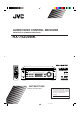
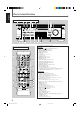
AUDIO/VIDEO CONTROL RECEIVER RECEPTEUR DE COMMANDE AUDIO/VIDEO RX-7520VBK RX-7520V AUDIO/VIDEO CONTROL RECEIVER FM/AM TUNING FM/AM PRESET FM MODE STANDBY COMPULINK Remote MASTER VOLUME MEMORY STANDBY/ON SURROUND ON/OFF INPUT ANALOG/DIGITAL BASS BOOST ADJUST SETTING FM MODE DVD MULTI DVD VCR TV SOUND TAPE/CDR FM AM INPUT ATT SURROUND MODE CONTROL DOWN UP SPEAKERS ON/OFF 1 2 CD SOURCE NAME PHONES INSTRUCTIONS MANUAL D’INSTRUCTIONS For Customer Use: Enter below the Model No.
Warnings, Cautions and Others/ Mises en garde, précautions et indications diverses Caution –– STANDBY/ON button! Disconnect the mains plug to shut the power off completely. The STANDBY/ON button in any position does not disconnect the mains line. The power can be remote controlled. CAUTION RISK OF ELECTRIC SHOCK DO NOT OPEN CAUTION: TO REDUCE THE RISK OF ELECTRIC SHOCK. DO NOT REMOVE COVER (OR BACK) NO USER SERVICEABLE PARTS INSIDE. REFER SERVICING TO QUALIFIED SERVICE PERSONNEL.
English CAUTION: TO PREVENT ELECTRIC SHOCK, MATCH WIDE BLADE OF PLUG TO WIDE SLOT, FULLY INSERT ATTENTION: POUR EVITER LES CHOCS ELECTRIQUES, INTRODUIRE LA LAME LA PLUS LARGE DE LA FICHE DANS LA BORNE CORRESPONDANTE DE LA PRISE ET POUSSER JUSQUAU FOND For Canada/pour Le Canada THIS DIGITAL APPARATUS DOES NOT EXCEED THE CLASS B LIMITS FOR RADIO NOISE EMISSIONS FROM DIGITAL APPARATUS AS SET OUT IN THE INTERFERENCE-CAUSING EQUIPMENT STANDARD ENTITLED “DIGITAL APPARATUS,” ICES-003 OF THE DEPARTMENT OF COMMUNIC
English Table of Contents Parts Identification ...................................... 2 Getting Started ........................................... 3 Before Installation ...................................................................... 3 Checking the Supplied Accessories ........................................... 3 Putting Batteries in the Remote Control .................................... 3 Connecting the FM and AM Antennas ....................................... 4 Connecting the Speakers .........
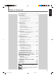
English Parts Identification Front Panel 2 3 FM/AM TUNING FM/AM PRESET 1 45 7 89 6 p RX-7520V AUDIO/VIDEO CONTROL RECEIVER FM MODE ANALOG DIGITAL AUTO LINEAR PCM DIGITAL STANDBY MEMORY SPK 1 2 L C OPERATION BASS BOOST TUNED STEREO AUTO MUTING SLEEP PRO LOGIC ΙΙ DSP H.PHONE INPUT ATT R VOLUME S.
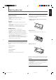
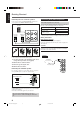
Before Installation General Precautions • DO NOT insert any metal object into the unit. • DO NOT disassemble the unit or remove screws, covers, or cabinet. • DO NOT expose the unit to rain or moisture. English Getting Started Putting Batteries in the Remote Control Before using the remote control, put two supplied batteries first. • When using the remote control, aim the remote control directly at the remote sensor on the unit. 1 On the back of the remote control, remove the battery cover.
English Getting Started Connecting the FM and AM Antennas AM Loop Antenna (supplied) Outdoor FM antenna (not supplied) If FM reception is poor, connect outdoor FM antenna. 75 FMAXIAL CO CO Standard type outdoor FM antenna (not supplied) Supplied FM antenna ANTENNA 75 FMAXIAL or FM 75 COAXIAL FM antenna (supplied) Extend the supplied FM antenna horizontally. Snap the tabs on the loop into the slots of the base to assemble the AM loop antenna.
English “NO” for the subwoofer, “LARGE” for the front speakers, and “SMALL” for the center and rear speakers are initial settings. To get best possible sound, change the subwoofer and speaker settings to fit your listening conditions.
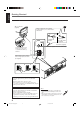
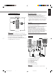
English Getting Started Connecting Audio/Video Components Connecting the rear and center speakers Connect rear speakers to the REAR SPEAKERS terminals and a center speaker to the CENTER SPEAKER terminals. You can connect the following audio/video components to this unit. Refer also to the manuals supplied with your components. Center speaker CENTER SPEAKER Audio Components • CD player* • Cassette deck or CD recorder* REAR SPEAKERS + Left rear speaker Turn off all components before connecting.
Cassette deck To audio input To audio output CD OUT (REC) TAPE CDR Use the cables with RCA pin plugs (not supplied). Connect the white plug to the audio left jack, the red plug to the audio right jack, and the yellow plug to the video jack. • If video components have S-video (Y/C-separation) and/or component video (Y, PB/CB, PR/CR) terminals, connect them using an S-video cable (not supplied) and/or component video cable (not supplied).
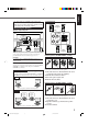
English Getting Started DVD player TV • When you connect the DVD player with stereo output jacks: COMPONENT VIDEO MONITOR OUT Y PB/CB PR/CR DVD player CD OUT (REC) MONITOR OUT AUDIO D DVD DVD RIGHT TAPE CDR LEFT C VCR IN (PLAY) FRONT OUT (REC) SUB WOOFER DVD DVD VCR CENTER OUT (REC) VCR REAR IN (PLAY) B A RIGHT IN (PLAY) LEFT COMPONENT VIDEO Y PB/CB PR/CR MONITOR OUT TV SOUND VIDEO S-VIDEO VIDEO RIGHT LEFT AUDIO SUBWOOFER OUT MONITOR OUT AUDIO RIGHT DVD LEFT
English Digital connections Notes: This receiver is equipped with two DIGITAL IN terminals—one digital coaxial terminal and one digital optical terminal. You can connect any digital component to one of the digital terminals using a digital coaxial cable (not supplied).
English Basic Operations Front Panel Remote Control Display STANDBY lamp RX-7520V AUDIO/VIDEO CONTROL RECEIVER FM/AM TUNING FM/AM PRESET STANDBY/ON AUDIO FM MODE ANALOG DIGITAL AUTO LINEAR PCM DIGITAL STANDBY MEMORY SPK 1 2 L C R BASS BOOST TUNED STEREO AUTO MUTING SLEEP PRO LOGIC ΙΙ DSP H.PHONE INPUT ATT VOLUME S.
Remote NOT When you connect a CD recorder to the TAPE/CDR jacks on the rear panel, change the source name shown on the display. 1 Press TAPE/CDR (SOURCE NAME). TAPE/CDR • Make sure “TAPE” appears on the display. 2 Press and hold SOURCE NAME (TAPE/CDR) until “ASSIGN CDR” appears on the display. SOURCE NAME Note: Without changing the source name, you can still use the connected component. However, there may be some inconvenience: – “TAPE” will appear on the display when you select the CD recorder.
English Basic Operations Listening Only with Headphones Changing the Display Brightness You must turn off both pairs of speakers when you listen with headphones. You can dim the display. 1 Connect a pair of headphones to the PHONES jack on the front Press DIMMER on the remote control. • Each time you press the button, the display dims and brightens alternately. panel. DIMMER 2 Press SPEAKERS ON/OFF 1 and SPEAKERS ON/OFF 2 so that neither the SPK 1 nor SPK 2 indicator appears on the display.
English Basic adjustment auto memory This receiver memorizes sound settings for each source when—: • turning off the power, • changing the source, and • assigning the source name. When you change the source, the memorized settings for the newly selected source are automatically recalled.
English Basic Settings Front Panel Remote Control Display SETTING RX-7520V AUDIO/VIDEO CONTROL RECEIVER FM/AM TUNING FM/AM PRESET FM MODE ANALOG DIGITAL AUTO LINEAR PCM DIGITAL STANDBY MEMORY SPK 1 2 L C R BASS BOOST TUNED STEREO AUTO MUTING SLEEP PRO LOGIC ΙΙ DSP H.PHONE INPUT ATT VOLUME S.
Press INPUT ANALOG/DIGITAL (or ANALOG/DIGITAL on the remote control) to select the digital input mode. INPUT ANALOG / DIGITAL ANALOG /DIGITAL INPUT ATT On the front panel 2 Press CONTROL UP 5/DOWN ∞ to select “DOLBY DIGITAL” or “DTS SURROUND” while “DIGITAL AUTO” still remains on the display. • Each time you press the button, the digital input mode changes as follows: When “DOLBY DIGITAL” or “DTS SURROUND” is selected, “DIGITAL AUTO” goes off.
English Basic Settings Selecting the Video Input Terminal Remote NOT This receiver is equipped with the component video input terminals for the DVD player which give you higher picture quality. When you use the component video input terminals for the DVD player, change the video input terminal setting. “NO” for the subwoofer, “LARGE” for the front speakers, and “SMALL” for the center and rear speakers are initial settings.
Register the sizes of all the connected speakers. • When you change your speakers, register the information about the speakers again. 1 L C S DIGITAL AUTO LINEAR PCM R FEET 3 • Each time you press the button, the display changes as follows: SMALL NONE 3 : Select this when you have not connected a speaker. (Not selectable for the front speakers) Repeat steps 1 and 2 to select the appropriate items for other speakers. CONTROL DOWN UP : Speaker distance is shown in feet.
English Basic Settings 2 Crossover frequency Small speakers cannot reproduce the bass sounds efficiently. If you use a small speaker in any position, this receiver automatically reallocates the bass sound elements assigned from the small speaker to large speakers. To use this function properly, set this crossover frequency level according to the size of the small speaker connected. • If you have selected “LARGE” for all speakers, this function will not take effect.
English Sound Adjustments Front Panel Remote Control Display RX-7520V AUDIO/VIDEO CONTROL RECEIVER FM/AM TUNING FM/AM PRESET FM MODE ANALOG DIGITAL AUTO LINEAR PCM DIGITAL STANDBY MEMORY SPK 1 2 L C R BASS BOOST TUNED STEREO AUTO MUTING SLEEP PRO LOGIC ΙΙ DSP H.PHONE INPUT ATT VOLUME S.
English Sound Adjustments Remote NOT Adjusting the Tone You can adjust the bass and treble sounds as you like. You can adjust the subwoofer output level if you have connected a subwoofer and set the subwoofer information correctly—“YES.” Before you start, remember.... There is a time limit in doing the following steps. If the setting is canceled before you finish, start from step 1 again.
English Tuner Operations Front Panel Remote Control FM/AM FM/AM TUNING PRESET 5/∞ 5/∞ FM MODE Display 10 keys RX-7520V AUDIO/VIDEO CONTROL RECEIVER FM/AM TUNING FM/AM PRESET PTY–PTY SEARCH–PTY FM MODE ANALOG DIGITAL AUTO LINEAR PCM DIGITAL STANDBY MEMORY SPK 1 2 L C R BASS BOOST TUNED STEREO AUTO MUTING SLEEP PRO LOGIC ΙΙ DSP H.PHONE INPUT ATT VOLUME S.
English Tuner Operations 4 Press MEMORY again while the selected channel number is flashing on the display. Selecting the FM Reception Mode MEMORY When an FM stereo broadcast is hard to receive or noisy, you can change the FM reception mode while receiving an FM broadcast. • You can store the FM reception mode for each preset station. (See page 21). The selected channel number stops flashing. The station is assigned to the selected channel number.
You can use the following Surround modes to reproduce a realistic sound field: ■ Dolby Surround • Dolby Pro Logic II • Dolby Digital ■ DTS Digital Surround ■ DAP modes ■ All Channel Stereo ■ Dolby Surround Dolby Pro Logic II* English Creating Realistic Sound Fields Dolby Digital* Used to reproduce multichannel sound tracks of the software ).
English Creating Realistic Sound Fields ■ DAP (Digital Acoustic Processor) modes ■ All Channel Stereo DAP modes have been designed to create important acoustic surround elements. This mode can reproduce a larger stereo sound field using all the connected (and activated) speakers. The sound heard in a live club, dance club, hall or pavilion consists of direct sound and indirect sound—early reflections and reflections from behind. Direct sounds reach the listener directly without any reflection.
English About Relations between Speaker Layouts and Surround Modes Available Surround modes will vary depending on how many speakers are used with this receiver. Make sure that you have set the speaker information correctly (see pages 16 to 18). • If only front speakers are connected, you cannot use Surround modes. • If rear speakers are not connected, you cannot use DAP modes and All Channel Stereo.
English Creating Realistic Sound Fields Before you start, remember.... • Make sure that you have set the speaker information correctly (see pages 16 to 18). • You cannot adjust the center speaker output level when you have set “CNTR SP” to “NONE.” • You cannot adjust the rear speaker output levels when you have set “REAR SP” to “NONE.” • Remember not to change the speaker setting while using any Surround modes; otherwise, it may be canceled when you deactivate the speakers required for the Surround mode.
Press SOUND. SOUND Press TEST to check if you can hear the sounds through all the speakers at the equal level. On the front panel: You can also use the buttons on the front panel to adjust the Surround modes. However, no test tone is available when using the buttons on the front panel. So make adjustments while listening to the sound of the source played back. The 10 keys are activated for sound adjustments.
English Creating Realistic Sound Fields When you select “PL II MUSIC,” you can go to the following adjustment. Remote NOT 4 Turn Panorama control on or off. 1) Press ADJUST repeatedly until “PANORAMA” (with the current setting)* appears on the display. ADJUST SETTING L C R Once you have adjusted the DAP modes and All Channel Stereo, the adjustment is memorized for each source. • You cannot use the DAP modes and All Channel Stereo if no rear speakers are connected.
1 Start playing 2 channel software—either analog or Linear PCM—and select the source. 2 Press SURROUND ON/OFF to activate Surround mode. SURROUND ON/OFF When Surround mode turns on, the last selected Surround mode will be activated. • Each time you press the button, Surround mode turns on and off alternately. 3 For DAP modes only: Adjust the effect level. 1) Press ADJUST repeatedly until “EFFECT” (with the current setting)* appears on the display. ADJUST SETTING * “EFFECT 3” is the initial setting.
English Using DVD MULTI Playback Mode This receiver provides the DVD MULTI playback mode for reproducing the analog discrete output mode of the DVD player. Before playing back a DVD, refer also to the manual supplied with the DVD player. From the remote control: 1 When you select “DVD MULTI” as the source to play, Surround mode is canceled, and the SURROUND ON/OFF and SURROUND MODE buttons do not work. 2 If you need to make any adjustments, go to the following steps.
The COMPU LINK remote control system allows you to operate JVC’s audio components through the remote sensor on the receiver. To use this remote control system, you need to connect JVC’s audio components through the COMPU LINK-4 (SYNCHRO) jacks (see below) in addition to the connections using cables with RCA pin plugs (see pages 6 and 7). • Make sure that the AC power cords of these components are unplugged before connection. Plug the AC power cords only after all connections are completed.
English AV COMPU LINK Remote Control System The AV COMPU LINK remote control system allows you to operate JVC’s video components (TV, VCR, and DVD player) through the receiver. This receiver is equipped with the AV COMPU LINK-III, which added a function to operate JVC’s video components through the video components terminals. To use this remote control system, you need to connect the video components you want to operate, following the diagrams below and the procedure on the next page.
2. Connect your VCR, DVD player, TV and this receiver as follows, using the cables with the monaural mini-plugs (not supplied). • See “CONNECTIONS 1” on the previous page. 3. Connect the audio input/output jacks on VCR, DVD player, TV and this receiver, using the cables with RCA pin plugs. • See pages 7 and 8. English 1. If you have already plugged your VCR, DVD player, TV and this receiver into the AC outlets, unplug their AC power cords first.
English Operating JVC’s Audio/Video Components You can use the remote control to operate other JVC’s components. Operating Audio Components Sound Adjustment You can always use the following buttons: SURROUND ON/OFF : Turn on or off the Surround modes. SURROUND MODE : Select the Surround modes. After pressing SOUND, you can use the following buttons for sound adjustment: SUBWOOFER +/– : Adjust the subwoofer output level. CENTER +/– : Adjust the center speaker output level.
English CD changer Cassette deck After pressing CD–DISC , you can use the following buttons for CD changer operations: After pressing TAPE/CDR, you can use the following buttons for cassette deck operations: 3 : Start playback. : Return to the beginning of the current (or previous) track. FF : Fast wind a tape from left to right. REW : Fast wind a tape from right to left. ¢ : Skip to the beginning of the next track. 7 : Stop playback or recording. 7 : Stop playback. 8 : Pause playback.
English Operating JVC’s Audio/Video Components Operating Video Components DVD player You can always perform the following operations: IMPORTANT: STANDBY/ON To operate JVC’s video components using this remote control: • You need to connect JVC’s video components through the AV COMPU LINK terminals (see page 32) in addition to the connections using cables with RCA pin plugs (see pages 7 and 8). • Some JVC’s VCRs can accept two types of the control signals— remote code “A” and “B.
By changing the transmittable signals, you can use the remote control supplied for this unit to operate other manufacturers’ equipment. • Refer also to the manuals supplied for the other products. • To operate these components with the remote control, first you need to set the manufacturers’ code each for TV, CATV converter, VCR and DVD player. • After replacing batteries of the remote control, set the manufacturers’ codes again.
English Operating Other Manufacturers’ Video Equipment 6 Try to operate your CATV converter by pressing STANDBY/ON TV/CATV. When your CATV converter turns on or off, you have entered the correct code. If there are more than one code listed for your brand of CATV converter, try each one until the correct one is entered. Manufacturers’ codes for CATV converter Manufacturer Echostar General Instrument Hamlin Pioneer RCA Scient Sony Zenith * “01” is the initial setting.
Manufacturers’ codes for DVD player Manufacturer 1 Press and hold STANDBY/ON DVD. 2 Press DVD. 3 Enter manufacturer’s codes using buttons 1 – 9, and 0. 4 Release STANDBY/ON DVD. Now, you can use the following buttons on the DVD player. STANDBY/ON DVD English To change the transmittable signals for operating a DVD player JVC Panasonic Philips Pioneer Sony Toshiba Yamaha Codes 01* 02 04 03 05 06 07 * “01” is the initial setting. : Turn on or off the DVD player.
English Troubleshooting Use this chart to help you solve daily operational problems. If there is any problem you cannot solve, contact your JVC’s service center. PROBLEM POSSIBLE CAUSE SOLUTION The power does not come on. The power cord is not plugged in. Plug the power cord into an AC outlet. No sound from speakers. Speaker signal cables are not connected. Check speaker wiring and reconnect if necessary. The SPEAKERS ON/OFF 1 and 2 buttons are not set correctly.
Specifications English Designs & specifications are subject to change without notice. Amplifier Output Power At Stereo operation: Front channels: 100 W per channel, min. RMS, driven into 8 Ω, 40 Hz to 20 kHz with no more than 0.8% total harmonic distortion. At Surround operation: Audio Audio Input Sensitivity/Impedance (1 kHz): Front channels: 100 W per channel, min. RMS, driven into 8 Ω at 1 kHz, with no more than 0.8% total harmonic distortion. Center channel: 100 W, min.
English Specifications FM tuner (IHF) Tuning Range: 87.5 MHz to 108.0 MHz Usable Sensitivity: Monaural: 12.8 dBf (1.2 µV/75 Ω) 50 dB Quieting Sensitivity: Monaural: Stereo: 21.3 dBf (3.2 µV/75 Ω) 41.3 dBf (31.5 µV/75 Ω) Signal-to-Noise Ratio (IHF-A weighted): Monaural: Stereo: 78 dB at 85 dBf 73 dB at 85 dBf Total Harmonic Distortion: Monaural: Stereo: 0.4% at 1 kHz 0.
VICTOR COMPANY OF JAPAN, LIMITED V EN, FR RX-7520VBK[C]Cover.pm5 J 2 02.2.