AUDIO/VIDEO CONTROL RECEIVER RECEPTEUR DE CONTROL AUDIO/VIDEO RX-778VBK ON STANDBY TV/CATV/DBS VCR POWER POWER CD TAPE/MD DVD TV/DBS PHONO FM/AM VCR ANALOG/DIGITAL SLEEP SURROUND CNTR ON/OFF 1 SURROUND TEST MODE 4 2 3 MENU REAR-L 5 6 ENTER DISC EFFECT SOUND SEA MODE REAR-R 7/P 8 9 SUBWOOFER 0 10 +10 RETURN FM MODE/MUTING 100+ AUDIO/ TV/VCR MASTER VOLUME RX-778V AUDIO/VIDEO CONTROL RECEIVER MENU CATV/DBS – SET STANDBY DIGITAL SOURCE FORMAT TEXT DISPLAY EXIT
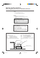
Warnings, Cautions and Others/ Mises en garde, précautions et indications diverses CAUTION To reduce the risk of electrical shocks, fire, etc.: 1. Do not remove screws, covers or cabinet. 2. Do not expose this appliance to rain or moisture. ATTENTION Afin d’éviter tout risque d’électrocution, d’incendie, etc.: 1. Ne pas enlever les vis ni les panneaux et ne pas ouvrir le coffret de l’appareil. 2. Ne pas exposer l’appareil à la pluie ni à l’humidité.
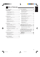
Parts Identification ...................................... 2 Using the DSP Modes ................................ 20 Getting Started ........................................... 3 Available DSP Modes According to the Speaker Arrangement .. 22 Adjusting the 3D-PHONIC Modes .......................................... 23 Adjusting the DAP Modes ....................................................... 23 Adjusting the Surround Modes ................................................ 24 Activating the DSP Modes .
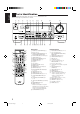
English Parts Identification Become familiar with the buttons and controls on the receiver before use. Refer to the pages in parentheses for details.
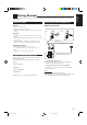
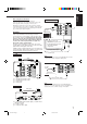
English Getting Started This section explains how to connect audio/video components and speakers to the receiver, and how to connect the power supply. Before Installation Connecting the FM and AM Antennas FM Antenna Connections General • Be sure your hands are dry. • Turn the power off to all components. • Read the manuals supplied with the components you are going to connect.
English Basic connecting procedure AM Antenna Connections Snap the tabs on the loop into the slots of the base to assemble the AM loop. ANTENNA FM 75 COAXIAL 4 3 2 1 1 RIG RIG HT AM LOOP AM Loop Antenna 1 1 HT RIG HT 1 Cut, twist and remove the insulation at the end of each speaker signal cable (not supplied). AM EXT 2 Turn the knob counterclockwise. 1 2 3 3 Insert the speaker signal cable. 4 Turn the knob clockwise.
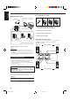
Connecting the rear and center speakers The required speaker impedance of the front speakers does differ depending on whether both the FRONT SPEAKERS 1 and FRONT SPEAKERS 2 terminals are used or only one of them is used. Connect rear speakers to the REAR SPEAKERS terminals and a center speaker to the CENTER SPEAKER terminals.
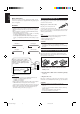
English Cassette deck or MD recorder Connecting Audio/Video Components You can connect the following audio/video components to this receiver. Refer also to the manuals supplied with your components.
English Video component connections TV and/or DBS tuner Use the cables with RCA pin plugs (not supplied). Connect the white plug to the audio left jack, the red plug to the audio right jack, and the yellow plug to the video jack. If DVD player and TV have S-video (Y/C-separation) terminals, connect them using S-video cables (not supplied). Connecting these video components through the S-video input/output terminals will give you better picture playback quality.
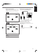
English Digital connections Connecting the Power Cord This receiver is equipped with two digital input terminals. You can connect any component to the digital terminals using digital optical cables (not supplied). Before plugging the receiver into an AC outlet, make sure that all connections have been made. Plug the power cord into an AC outlet. IMPORTANT: • When connecting the DVD player or the DBS tuner using the digital terminal, you also need to connect it to the video jack on the rear.
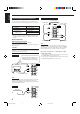
English Basic Operations The following operations are commonly used when you play any sound source. IMPORTANT: From the remote control: When using the remote control, check to see if its remote control mode selector is set to the correct position: To operate an audio system, TV, and VCR, set it to “AUDIO/TV/VCR.” To operate a CATV converter and DBS tuner, set it to “CATV/DBS.” Press one of the source selecting buttons.
English When playing a digital source through a digital terminal • The DIGITAL SOURCE FORMAT lamps on the front panel indicate what type of the digital signal comes into the receiver. DIGITAL SOURCE FORMAT DOLBY DIGITAL LINEAR PCM DOLBY DIGITAL: Lights up when Dolby Digital signals (see page 21) come in. LINEAR PCM: Lights up when Linear PCM signals come in. • The signal indicators also light up on the display to indicate the incoming channel signals.
English Listening only with headphones Attenuating the Input Signal 1. Connect a pair of headphones to the PHONES jack on the front panel. 2. Press SPEAKERS 1 and/or 2 so that no lamps on the buttons are turned on. When the input level of the playing source is too high, the sounds will be distorted. If this happens, you need to attenuate the input signal level to prevent the sound distortion.
English Basic Settings Some of the following settings are required after connecting and positioning your speakers in your listening room, while others will make operations easier. IMPORTANT: When using the remote control, check to see if its remote control mode selector is set to the correct position: To operate this receiver, set it to “AUDIO/TV/ VCR” (except when selecting the DBS tuner as the source).
SETTING 1. Press SETTING repeatedly until “DIGITAL IN” appears on the display. English 2. Press ANALOG/DIGITAL to change the input mode. On the front panel ONLY: ANALOG/DIGITAL • Each time you press the button, the input mode alternates between the digital input and analog input. The display changes to show the current setting. Notes: DIGITAL 2 terminal setting * Before pressing TV/DBS, make sure that the remote control mode selector on the remote control is set to “CATV/DBS.
English Setting the Speakers for the DSP Modes Center Delay Time Setting Before you start, remember... • There is a time limit in doing the following steps. If the setting is canceled before you finish, start from step 1 again. Register the delay time of the sound from the center speaker, comparing that of the sound from the front speakers. If the distance from your listening point to the center speaker is equal to that to the front speakers, select 0 msec.
English MULTI JOG Crossover Frequency Setting Small speaker cannot reproduce the bass sound very well. So, if you have used a small speaker any for the front, center, or rear channels, this receiver automatically reallocate the bass elements, originally assigned to the channel for which you have connected the small speaker, to another channel (for which you have connected the large speaker).
English Storing the Basic Settings and Adjustments — One Touch Operation JVC’s One Touch Operation function is used to assign and store different sound settings for each different playing source. By using this function, you do not have to change the settings every time you change the source. The stored settings for the newly selected source are automatically recalled.
English Receiving Radio Broadcasts You can browse through all the stations or use the preset function to go immediately to a particular station. IMPORTANT: When using the remote control, check to see if its remote control mode selector is set to the correct position: To operate this receiver, set it to “AUDIO/TV/ VCR” (except when selecting the DBS tuner as the source). Using Preset Tuning AUDIO/ TV/VCR Once a station is assigned to a channel number, the station can be quickly tuned.
English To tune in a preset station Note: On the front panel: When using the FM MODE/MUTING button on the remote control, be sure that the 10 keys are activated for tuner, not for the CD and others. (See page 41.) SOURCE SELECTOR 1. Turn SOURCE SELECTOR to select the band (FM or AM). The last received station of the selected band is tuned in. Assigning Names to Preset Stations TUNER PRESET 2. Press TUNER PRESET. 3. Turn MULTI JOG until you find the channel you want.
English Using the SEA Modes The SEA (Sound Effect Amplifier) modes give you control of the way your music sounds. IMPORTANT: Creating Your Own SEA Mode When using the remote control, check to see if its remote control mode selector is set to the correct position: To operate this receiver, set it to “AUDIO/TV/ VCR” (except when selecting the DBS tuner as the source). You can adjust and store your own SEA adjustment into memory (SEA USERMODE). AUDIO/ TV/VCR CATV/DBS Before you start, remember...
English Using the DSP Modes The built-in Surround Processor provides three types of the DSP (Digital Signal Processor) mode — 3D-PHONIC mode, DAP (Digital Acoustic Processor) mode and Surround mode. 3D-PHONIC modes DAP modes The 3D-PHONIC mode gives you such a nearly surround effect as it is reproduced through the Dolby Surround decoder, which is widely used to reproduce sounds with a feeling of movement like those experienced in movie theaters.
Notes: With this receiver, you can use two types of the Surround mode. Following modes cannot be used when only the front speakers are connected to this receiver (without the rear speakers or center speaker). • The DSP modes have no effect on monaural sources. • The DSP modes cannot be used for recording an analog source. • The PRO LOGIC indicator lights up when the Dolby Pro Logic decoder built in this receiver is activated.
English Available DSP Modes According to the Speaker Arrangement Available DSP modes will vary depending on how many speakers are used with this receiver. Make sure that you have set the speaker information correctly (see page 14).
When using the remote control, check to see if its remote control mode selector is set to the correct position: To operate this receiver, set it to “AUDIO/TV/ VCR” (except when selecting the DBS tuner as the source). AUDIO/ TV/VCR CATV/DBS DSP EFFECT 1 On the front panel: DSP MODE 1. Press DSP MODE repeatedly until “3D ACTION (or 3D DIGITAL)” or “3D THEATER” appears on the display. The 3D-PHONIC, DSP, PRO LOGIC and selected 3D-PHONIC mode indicators also light up on the display.
English 3. Adjust the effect level. 1) Press BALANCE/SURROUND ADJUST repeatedly until “DSP EFFECT” appears on the display. The display changes to show the current setting. 2) Turn MULTI JOG to select the effect level. • As you turn it, the effect level changes as follows: DSP EFFECT 1 DSP EFFECT 2 DSP EFFECT 5 BALANCE/SURROUND ADJUST Once you have adjusted the Surround modes, the adjustment is memorized for each Surround mode.
2. Adjust the speaker output levels. • You can adjust the speaker output levels without outputting the test tone. • No test tone comes out of the center speaker when “CENTER SPK” is set to “NONE” (see page 14). • No test tone comes out of the rear speakers when “REAR SPK” is set to “NONE” (see page 14). • If the TV is turned on and the proper video input is selected on the TV, the test tone screen will appear on the TV.
English On the front panel: 3. Press TEST to check the speaker output balance. TEST You can also use the buttons on the front panel to adjust the Surround modes. However, no test tone is available when using the buttons on the front panel. So, make adjustments while listening to the sound of the source played back.
You can use only one DSP mode at a time. When a DSP mode is activated, another DSP mode is canceled if in use. For Dolby Pro Logic and Dolby Digital Surround On the front panel: 1. Press DOLBY SURROUND so that the lamp on the button lights up. English For the other DSP modes Activating the DSP Modes DOLBY SURROUND On the front panel: 1. Press DSP MODE repeatedly until the mode you want appears on the display. DSP MODE • Each time you press the button, the DSP modes change.
English Using the On-Screen Menus You can use the Menus on the TV screen to control the receiver. To use this function, you need to connect the TV to the MONITOR OUT jack on the rear panel (see page 7), and set the TV’s input mode to the proper position to which the receiver is connected. • When the TV’s input mode is incorrect; for example, a different video input or TV tuner mode is selected, you cannot show the Menus on the TV screen.
1. Press MENU. The MAIN MENU appears on the TV. • Pressing one of the % / fi / @ / # buttons also displays the MAIN MENU. 2. Press % / fi to move to “SOUND CONTROL,” then press @ / #. The SOUND CONTROL menu appears. 3. Press % / fi to move to “LOUDNESS.” English Listening at Low Volume (Loudness) (Also see page 11) 3. Press % / fi to move to “SUBWFR LEVEL.” 4. Press @ / # to adjust the subwoofer output level. 5. When you finish, press EXIT repeatedly until the menu disappears from the TV.
English For Dolby Pro Logic: “TEST TONE”: Output a test tone. “CENTER LEVEL”: Adjust the center speaker output level.** “REAR L LEVEL”: Adjust the left rear speaker output level.* “REAR R LEVEL”: Adjust the right rear speaker output level.* For Dolby Digital Surround: “TEST TONE”: Output a test tone. “CENTER LEVEL”: Adjust the center speaker output level.** “REAR L LEVEL”: Adjust the left rear speaker output level.* “REAR R LEVEL”: Adjust the right rear speaker output level.
1. Press MENU. The MAIN MENU appears on the TV. • Pressing one of the % / fi / @ / # buttons also displays the MAIN MENU. 2. Press % / fi to move to “SETTING,” then press @ / #. The SETTING 1 or SETTING 2 menu appears. 3. Press % / fi to move to the item you want to set or adjust, then press @ / #. • To go to the SETTING 2 to “NEXT menu, move PAGE,” then press @ / #. • To go back to the SETTING 1 menu, move to “PREVIOUS PAGE,” then press @ / #.
English Storing the Preset Stations (Also see page 17) 1. Press MENU. The MAIN MENU appears on the TV. • Pressing one of the % / fi / @ / # buttons also displays the MAIN MENU. 2. Press % / fi to move to “TUNER CONTROL,” then press @ / #. The TUNER CONTROL menu appears. 3. Tune into a station on the TUNER CONTROL menu, referring to “Operating the Tuner” on the previous page. 4. Press % / fi to move to “PRESET MEMORY,” then press @ / #. 6. Press % / fi to move to “PRESET NAME,” then press SET.
The COMPU LINK remote control system allows you to operate JVC audio components through the remote sensor on the receiver. To use this remote control system, you need to connect JVC audio components through the COMPU LINK-3 (SYNCHRO) jacks (see below) in addition to the connections using cables with RCA pin plugs (see page 6). • Make sure that the AC power cords of these components are unplugged before connection. Plug the AC power cords only after all connections are complete.
English TEXT COMPU LINK Remote Control System The TEXT COMPU LINK remote control system has been newly developed to deal with the disc information recorded in the CD Text* and MDs. Using these information in the discs, you can operate the CD player or MD recorder equipped with the TEXT COMPU LINK remote control system through the receiver. CONNECTIONS: FUNCTIONS: To use this remote control system, you need to connect the CD player and/or MD recorder you want to operate, following the procedures below.
To use this remote control system, you need to connect the TV to the MONITOR OUT jack on the rear panel (see page 7), and set the TV’s input mode to the proper position to which the receiver is connected. Make sure you have connected the CD player or MD recorder equipped with the TEXT COMPU LINK remote control system. If not, you cannot use the following functions.
English Searching for a Disc (Only for the CD player) Search for a disc by its performer: 1. Press TEXT DISPLAY while “CD” is selected as the source. The Disc Information screen appears on the TV. 2. Press % / fi to move to “SEARCH,” then press SET. The DISC SEARCH screen appears . 3. Press % / fi to move to “PERFORMER”, then press SET. The PERFORMER SEARCH screen appears. 4. Press % / fi / @ / # to move in front of the first character of the performer you want to search, then press SET.
1. Press TEXT DISPLAY while “CD” is selected as the source. The Disc Information screen appears on the TV. 2. Press % / fi to move to “SEARCH,” then press SET. The DISC SEARCH screen appears. 3. Press % / fi to move to “GENRE”, then press SET. The GENRE SEARCH screen appears. 4. Press % / fi to move to the genre you want to search, then press SET. To show the unseen genres, press % / fi until they appear. Disc search starts, then the SEARCH RESULT screen, showing the disc titles, appears. 5.
English 4. Repeat step 3 until you finish putting a performer name (up to 32 characters). To insert a space, press % / fi / @ / # to move to , then press SET. To correct an incorrect character: to + or =, then press 1) Press % / fi / @ / # to move SET until the incorrect character is selected. 2) Press % / fi / @ / # to move to , then press SET to erase the character. 3) Press % / fi / @ / # to move in front of the correct character, then press SET to enter a correct character. 5.
The AV COMPU LINK remote control system allows you to operate JVC video components (TV, VCR, and DVD player) through the receiver. To use this remote control system, you need to connect the video components you want to operate, follow the diagrams below and the procedure on the next page. CONNECTIONS 1: CAUTION: TV VCR The AV COMPU LINK remote control system cannot control the DBS tuner connected to the TV SOUND/DBS jacks.
English 1. If you have already plugged your VCR, DVD player, TV, and this receiver into the AC outlets, unplug their AC power cords first. 2. Connect your VCR, DVD player, TV, and this receiver, using the cables with the monaural miniplugs (not supplied). • See “CONNECTIONS 1” on the previous page. 3. Connect the audio input/output jacks on VCR, DVD player, TV, and this receiver using the cables with RCA pin plug • See page 7. 4.
You can operate JVC’s audio and video components with this receiver’s remote control, since control signals for JVC components are preset in the remote control. IMPORTANT: Sound control section (Amplifier) To operate JVC’s audio components using this remote control: • You need to connect JVC audio components through the COMPU LINK-3 (SYNCHRO) jacks (see page 33) in addition to the connections using cables with RCA pin plugs (see page 6).
English Turntable VCR After pressing PHONO (with the remote control mode selector set to “AUDIO/TV/VCR”), you can perform the following operations on a turntable: You can always perform the following operations (with the remote control mode selector set to “AUDIO/TV/VCR”): PLAY: STOP: Starts playing. Stops operations.
This remote control supplied with the receiver can transmit control signals for other manufacturers’ VCRs, TVs, CATV converters and DBS tuners. By changing the transmittable signals from preset ones to the other manufacturers’, you can operate the other manufacturer’s components using this remote control. When operating the other manufacturers’ components, refer also to the manuals supplied with them.
English To change the transmittable signals for operating a CATV converter or DBS tuner 3. Press VCR. 4. Enter manufacturer’s code (two digits) using buttons 1 – 9, and 0. 1. Set the remote control mode to “CATV/DBS.” See the list below. 2. Press and hold TV/CATV/DBS POWER. Examples: For a JVC product, press 0, then 1. For a Funai product, press 1, then 0. 3. Press TV/DBS. 4. Enter manufacturer’s code (three digits) using buttons 1 – 9, and 0. See the list below.
Use this chart to help you solve daily operational problems. If there is any problem you cannot solve, contact your JVC service center. PROBLEM POSSIBLE CAUSE SOLUTION The display does not light up. The power cord is not plugged in. Plug the power cord into an AC outlet. No sound from speakers. Speaker signal cables are not connected. Check speaker wiring and reconnect if necessary. The SPEAKERS 1 and 2 buttons are not set correctly. Press SPEAKERS 1 and 2 correctly.
English Specifications Amplifier Output Power At Stereo operation: Front channels: 110 watts per channel, min. RMS, driven into 8 ohms, 20 Hz to 20 kHz with no more than 0.06% total harmonic distortion. At Surround operation: Front channels: 100 watts per channel, min. RMS, driven into 8 ohms at 1 kHz, with no more than 0.8% total harmonic distortion. Center channel: 100 watts, min. RMS, driven into 8 ohms at 1 kHz, with no more than 0.8% total harmonic distortion.
VICTOR COMPANY OF JAPAN, LIMITED V EN, FR RX-778V[C]COVER/1 J 2 99.4.