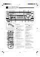
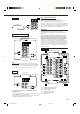
AUDIO/VIDEO CONTROL RECEIVER RX-8010RBK / RX-8012RSL CATV/DBS VCR 1 TV AUDIO DVD DVD MUILTI CD FM/AM TV/DBS VIDEO CDR PHONO VCR 1 VCR 2 TAPE/MD USB SURROUND DSP ON/OFF MODE LINE DIF.
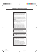
Warnings, Cautions and Others IMPORTANT for the U.K. DO NOT cut off the mains plug from this equipment. If the plug fitted is not suitable for the power points in your home or the cable is too short to reach a power point, then obtain an appropriate safety approved extension lead or consult your dealer. BE SURE to replace the fuse only with an identical approved type, as originally fitted.
SAFETY INSTRUCTIONS “SOME DOS AND DON’TS ON THE SAFE USE OF EQUIPMENT” This equipment has been designed and manufactured to meet international safety standards but, like any electrical equipment, care must be taken if you are to obtain the best results and safety is to be assured. Do read the operating instructions before you attempt to use the equipment.
Table of Contents Parts Identification ...................................... 2 Creating a Surround Field in Your Room ....... 28 Getting Started ........................................... 3 7 Surround modes .................................................................... 28 7 DSP modes ........................................................................... 28 Reproducing the Sound Field ....................................................
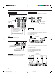
Parts Identification Become familiar with the buttons and controls on the receiver before use. Refer to the pages in parentheses for details.
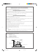
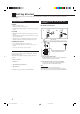
Getting Started This section explains how to connect audio/video components and speakers to the receiver, and how to connect the power supply. Before Installation Connecting the FM and AM (MW/LW) Antennas General • Be sure your hands are dry. • Turn the power off to all components. • Read the manuals supplied with the components you are going to connect.
AM (MW/LW) Antenna Connections Snap the tabs on the loop into the slots of the base to assemble the AM (MW/LW) loop. ANTENNA FM 75 COAXIAL AM LOOP 2 1 4 3 1 Cut, twist and remove the insulation at the end of each speaker signal cable (not supplied). AM (MW/LW) Loop Antenna AM EXT Basic connecting procedure 2 Turn the knob counterclockwise. 2 1 3 3 Insert the speaker signal cable. 4 Turn the knob clockwise.
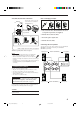
About the speaker impedance Connecting Audio/Video Components The required speaker impedance of the front speakers does differ depending on whether both the FRONT SPEAKERS 1 and FRONT SPEAKERS 2 terminals are used or only one of them is used. CASE 1 When you connect only one pair of front speakers Front speaker 1 Front speaker 1 Use front speakers with 8 Ω – 16 Ω impedance. CASE 2 When you connect two pairs of front speakers You can connect the following audio/video components to this receiver.
CD player RIGHT LEFT AUDIO REAR PHONO CD player CD OUT (REC) TAPE MD To audio output IN (PLAY) OUT (REC) CDR Cassette deck or MD recorder IN (PLAY) Cassette deck To audio output To audio input RIGHT AUDIO LEFT REAR PHONO Video component connections Use the cables with RCA pin plugs (not supplied). Connect the white plug to the audio left jack, the red plug to the audio right jack, and the yellow plug to the video jack.
TV and/or DBS tuner Video camera When connecting the TV to the AUDIO jacks (TV SOUND/ DBS), DO NOT connect the TV’s video output to these video input terminals. The VIDEO input terminals on the front panel are convenient when connecting and disconnecting the equipment frequently.
Notes: Digital Connections This receiver is equipped with four DIGITAL IN terminals — one digital coaxial terminal and three digital optical terminals, and one DIGITAL OUT terminal. IMPORTANT: • When connecting the DVD player, digital TV broadcast tuner or DBS tuner using the digital terminals, you also need to connect it to the video terminal on the rear. Without connecting it to the video terminal, you can view no playback picture.
USB Connection This receiver is equipped with a USB terminal on the front panel. You can connect your PC to this terminal and enjoy sound reproduced through your PC. When you connect your PC for the first time, follow the procedure below. • Remember you cannot send any signal or data to your PC from this receiver. 5. Check if the drivers are correctly installed. 1. Open the Control Panel on your PC: Select [Start] = [Settings] = [Control Panel] 2.
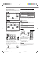
Connecting the Power Cord Before plugging the receiver into an AC outlet, make sure that all connections have been made. Putting Batteries in the Remote Control Before using the remote control, put two supplied batteries first. When using the remote control, aim the remote control directly at the remote sensor on the receiver. Plug the power cord into an AC outlet. Keep the power cord away from the connecting cables and the antenna. The power cord may cause noise or screen interference.
Basic Operations The following operations are commonly used when you play any sound source. You can also use on-screen menus for most of the operations mentioned in this section. For details, see page 40. Before using the remote control From the remote control: How to confirm the remote control operation mode The display window on the remote control shows following information for about 10 seconds when you press certain buttons on the remote control, so that you can confirm which operation you do.
On the front panel: Notes: • When connecting an MD recorder (to the TAPE/MD jacks), and a DBS tuner (to the TV SOUND/DBS jacks), change the source names shown on the display. For details, see page 16. • When you press one of the source selecting buttons on the remote control marked with an asterisk (*), the receiver automatically turns on. Signal and speaker indicators on the display The signal indicators light up in the following cases: • Only the indicators for the incoming signals light up.
Selecting the Front Speakers Muting the Sound On the front panel ONLY: When you have connected two pairs of the front speakers, you can select which to use. To use the speakers connected to the FRONT SPEAKERS 1 terminals, press SPEAKERS ON/OFF 1 so that SPEAKERS 1 indicator lights up on the display. Make sure that the SPEAKERS 2 is not lit on the display.
Attenuating the Input Signal Activating the Subwoofer Sound You can cancel the subwoofer sound even though you have connected a subwoofer and have set “SUBWOOFER” to “YES” (see page 17). This is useful when enjoying surround sound at night. On the front panel ONLY: Press SUBWOOFER OUT ON/OFF to SUBWOOFER OUT ON/OFF cancel the subwoofer sound output. Each time you press the button, the subwoofer sound output is deactivated (“SUBWFR OFF”) or activated (“SUBWFR ON”).
Adjusting the Equalization Patterns Using the Sleep Timer You can adjust equalization to your preference. • You can do this setting for each source. Using the Sleep Timer, you can fall asleep to music and know the receiver will turn off by itself rather than play all night. Before you start, remember.... • There is a time limit in doing the following steps. If the setting is canceled before you finish, start from step 1 again. From the remote control ONLY: On the front panel: 1.
Basic Settings Some of the following settings are required after connecting and positioning your speakers in your listening room, while others will make operations easier. You can also use on-screen menus for most of the operations mentioned in this section. For details, see page 40. Adjusting the Front Speaker Output Balance If the sounds you hear from the front right and left speakers are unequal, you can adjust the speaker output balance. • You can do this setting for each source.
Setting the Speakers for a Surround Field Setting the Subwoofer Information Register whether you have connected a subwoofer or not. Before you start, remember.... • There is a time limit in doing the following steps. If the setting is canceled before you finish, start from step 1 again. On the front panel ONLY: 1. Press SETTING repeatedly until “SUBWOOFER” appears on the display. CT SETTING Before you start, remember.... • There is a time limit in doing the following steps.
Center Delay Time Setting Register the delay time of the sound from the center speaker, comparing to that of the sound from the front speakers. If the distance from your listening point to the center speaker is equal to that to the front speakers, select 0 ms. As the distance to the center speaker becomes shorter, increase the delay time. • 1 msec increase (or decrease) in delay time corresponds to 30 cm decrease (or increase) in distance. • When shipped from the factory, the delay time is set to 0 ms.
Low Frequency Effect Attenuator Setting If the bass sound is distorted while playing back a source using Dolby Digital or DTS Digital Surround, follow the procedure below. When you use the digital input terminals, you have to register what components are connected to which terminals (DIGITAL IN 1/2/3/4). On the front panel ONLY: 1. Press SETTING repeatedly until “LFE ATT” (Low Frequency Effect Attenuator) appears on the display. CT SETTING Before you start, remember...
2. Press CONTROL UP 5/DOWN ∞ to select the appropriate digital terminal settings.
When playing a software encoded with the Dolby Digital or DTS Digital Surround, “DGTL AUTO” may not work properly and the following symptoms may occur: • Sound does not come out at the beginning of playback. • Noise comes out while using the searching or skipping chapters or tracks. In this case press CONTROL UP 5/ DOWN ∞ to select “DGTL D.D” or “DGTL DTS” while “DGTL AUTO” still remains on the display. • Each time you press the button, the input mode changes as follows.
Showing the Text Information on the Display When you have connected an MD recorder or CD player equipped with TEXT COMPU LINK remote control system (see page 46), you can show the text information, such as disc title or track title, on the display of this receiver. To show it on the display, follow the procedure below. Before you start, remember.... • There is a time limit in doing the following steps. If the setting is canceled before you finish, start from step 1 again. On the front panel ONLY: 1.
Receiving Radio Broadcasts You can browse through all the stations or use the preset function to go immediately to a particular station.You can also use on-screen menus for most of the operations mentioned in this section. For details, see page 40. Tuning in Stations Manually Using Preset Tuning On the front panel ONLY: 1. Press FM/AM to select the band (FM or AM — MW/LW). FM/AM The FM/AM lamp on the front panel button lights up. The last received station of the selected band is tuned in.
To tune in a preset station Selecting the FM Reception Mode On the front panel: 1. Press FM/AM to select the band (FM or AM — MW/LW). When an FM stereo broadcast is hard to receive or noisy FM/AM The FM/AM lamp on the front panel button lights up. The last received station of the selected band is tuned in. • Each time you press the button, the band alternates between FM and AM (MW/LW). 2. Press FM/AM PRESET 5/∞ until you find the channel you want.
Using the RDS (Radio Data System) to Receive FM Stations RDS allows FM stations to send an additional signal along with their regular program signals. For example, the stations send their station names, as well as information about what type of program they broadcast, such as sports or music, etc. When tuned to an FM station which provides the RDS service, the RDS indicator lights up on the display. With the receiver, you can receive the following types of RDS signals.
On the front panel: 1. Press PTY SEARCH while listening to an FM station. PTY SEARCH None “PTY SELECT” flashes on the display. 2. Press CONTROL UP 5/DOWN ∞ until the PTY code you want appears on the display, while “PTY SELECT” is flashing. CONTROL DOWN UP The display gives you the PTY codes described to the right. 3. Press PTY SEARCH again, while the PTY code selected in the previous step is still on the display.
Switching to a Broadcast Program of Your Choice Temporarily Another convenient RDS service is called “EON (Enhanced Other Network).” The EON indicator lights up while receiving an FM station with the EON code. (The EON indicator also lights up while receiving an AM station but the EON function will not work.
Creating a Surround Field in Your Room The built-in Surround Processor provides Surround mode and four types of the DSP (Digital Signal Processor) mode — DAP (Digital Acoustic Processor) mode, 5 CH/4 CH Stereo mode, 3D-PHONIC mode, and HEADPHONE DSP mode. With this receiver, you can use a Surround mode and a DSP mode at the same time. Once you have adjusted Surround and/or DSP modes, the adjustments done for each source are memorized.
3D-PHONIC modes The 3D-PHONIC mode gives you such a nearly surround effect as is reproduced through the Dolby Surround decoder, which is widely used to reproduce sounds with a feeling of movement like those experienced in movie theaters. The 3D-PHONIC mode is the result of research on sound localization technology carried out at JVC for many years. This mode can be used when the front speakers are connected to this receiver (without respect to the rear/center speaker connection).
Available DSP Modes According to the Speaker Arrangement Available DSP modes will vary depending on how many speakers are used with this receiver. Make sure that you have set the speaker information correctly (see page 17).
5. Select the speaker you want to adjust. Adjusting the Surround Modes You can also use a Surround mode with a DAP mode (see page 34). • To select the center speaker level, press CENTER. “CTR” appears on the remote control display window. • To select the left rear speaker level, press REAR L. “REARL” appears on the remote control display window. • To select the right rear speaker level, press REAR R. “REARR” appears on the remote control display window. Before you start, remember...
2. Press SURROUND ON/OFF to activate an appropriate Surround mode — PRO LOGIC, DOLBY DIGITAL or DTS SURROUND. SURROUND ON/OFF The SURROUND ON/OFF lamp on the front panel button lights up. • Each time you press the button, the Surround mode turns on and off alternately. • When “PRO LOGIC” is selected, the PRO LOGIC indicator lights up on the display. 3. Adjust the speaker output levels. 1) Press LEVEL ADJUST repeatedly until one of the following indications appears on the display.
4. Adjust the overall levels of the effect. 1) Press EFFECT repeatedly until “EFFECT” appears on the display. The display shows the current setting. 2) Press CONTROL UP 5/DOWN ∞ to select the effect level you want. • Each time you press the button, the display changes to show the following: EFFECT 1 EFFECT 2 EFFECT SETT CONTROL DOWN UP EFFECT 3 1) Press EFFECT repeatedly until “ROOMSIZE” appears on the display. The display shows the current setting.
9. Press LIVENESS to adjust the liveness. • Each time you press the button, the liveness changes as follows: LIVENESS 1 LIVENESS 2 LIVENESS 5 LIVENESS 6 LIVENESS 3 LIVENESS 4 5. Press TEST to check the speaker output balance. 4 MENU “TEST TONE L” starts flashing on the display, and a test tone comes out of the speakers in the following order: TEST TONE L As the number increases, the attenuation level of reflections over time decreases so that acoustics change from “Dead” to “Live.
11.Press EFFECT to adjust the overall level of the effect. EFFECT 2 MENU • Each time you press the button, the effect level changes as follows: EFFECT 1 EFFECT 2 EFFECT 5 EFFECT 3 EFFECT 4 As the number increases, DAP effect becomes stronger. (Normally set it to “EFFECT 3.”) 12.Press ROOM SIZE to adjust the room size (sense of spaciousness).
7. Adjust the room size (sense of spaciousness). 1) Press EFFECT repeatedly until “ROOMSIZE” appears on the display. The display shows the current setting. 2) Press CONTROL UP 5/DOWN ∞ to select the room size you want. • Each time you press the button, the display changes to show the following: ROOMSIZE 1 ROOMSIZE 2 ROOMSIZE 5 EFFECT SETTIN CONTROL DOWN UP ROOMSIZE 3 ROOMSIZE 4 As the number increases, the interval between reflections increases so that you will feel as if you were in a larger room.
+ 4. Press LEVEL +/– to adjust the speaker output levels (–10 dB to +10 dB). ∗BAL L ∗ CH/ LEVEL − 5. Press SOUND. ∗BAL R SOUND • To adjust other speaker output levels, repeat steps 3 and 4. 6. Press CTR TONE to select the center tone level you want — for 5 CH Stereo mode only. CTR TONE 5 ENTER 3. Adjust the center tone.
6. Press CTR TONE to select the center tone level you want. CTR TONE 5 ENTER • Each time you press the button, the display changes to show the following: (Softer) Use this column to write down your DSP mode adjustments for your future reference. CTR TONE 3 CTR TONE 2 CTR TONE 1 ––––––––––––––– MEMO ––––––––––––––– (Soft) (Flat) CTR TONE 5 CTR TONE 4 (Sharper) (Sharp) To make the dialogue softer, select “CTR TONE 1” or “CTR TONE 2.
Using the DVD MULTI Playback Mode This receiver provides the DVD MULTI playback mode for reproducing the analog discrete output mode of the DVD player. Before playing back a DVD, refer also to the manual supplied with the DVD player. You can also use on-screen menus. For details, see page 40. Activating the DVD MULTI Playback Mode You can adjust the DVD MULTI playback mode while playing back a DVD using the analog discrete output mode on the DVD player.
Using the On-Screen Menus You can use the Menus on the TV screen to control the receiver. To use this function, you need to connect the TV to the MONITOR OUT jack on the rear panel (see page 7), and set the TV’s input mode to the proper position to which the receiver is connected. • When the TV’s input mode is incorrect; for example, if a different video input or TV tuner mode is selected, you cannot show the Menus on the TV screen.
For Surround mode, Surround mode with DAP mode: “TEST TONE”: Output a test tone. “L/R BALANCE”: Adjust the right and left balance of the front speakers. “CENTER LEVEL”: Adjust the center speaker output level. * “REAR L LEVEL”: Adjust the left rear speaker output level. ** “REAR R LEVEL”: Adjust the right rear speaker output level. ** “SUBWFR LEVEL”: Adjust the subwoofer output level. *** For DAP mode: “L/R BALANCE”: Adjust the right and left balance of the front speakers.
7. Press 5 / ∞ to move to “EFFECT ADJUST,” then press 2 / 3. The EFFECT ADJUST menu appears. 8. Press 5 / ∞ to move to the item you want to set or adjust, then press 2 / 3. On these adjustment menus, you can do the followings: For Surround mode: “CENTER TONE”: Select the center tone level. * For DAP mode, Surround mode with DAP: “EFFECT LEVEL”: Adjust the surround effect level. “ROOM SIZE”: Adjust the room size effect. “LIVENESS”: Adjust the liveness level. “CENTER TONE”: Select the center tone level.
Selecting the Line Direct Function (Also see page 14) 1. Press MENU. Activating the Subwoofer Sound (Also see page 14) 1. Press MENU. The MENU appears on the TV. • Pressing one of the 5 / ∞ / 2 / 3 buttons also displays the MENU. 2. Press 5 / ∞ to move to “SOUND CONTROL,” then press 2 / 3. The SOUND CONTROL menu appears. The MENU appears on the TV. • Pressing one of the 5 / ∞ / 2 / 3 buttons also displays the MENU. 2. Press 5 / ∞ to move to “SOUND CONTROL,” then press 2 / 3.
Storing the Preset Stations (Also see page 23) 1. Press MENU. The MENU appears on the TV. • Pressing one of the 5 / ∞ / 2 / 3 buttons also displays the MENU. 2. Press 5 / ∞ to move to “TUNER CONTROL,” then press 2 / 3. The TUNER CONTROL menu appears. 3. Tune into a station on the TUNER CONTROL menu, referring to “Operating the Tuner”. 4. Press 5 / ∞ to move to “PRESET MEMORY,” then press 2 / 3. moves to “PRESET CH” and the channel number starts flashing. 5.
COMPU LINK Remote Control System The COMPU LINK remote control system allows you to operate JVC audio components through the remote sensor on the receiver. To use this remote control system, you need to connect JVC audio components through the COMPU LINK (SYNCHRO) jacks (see below) in addition to the connections using cables with RCA pin plugs (see pages 5 and 6). • Make sure that the AC power cords of these components are unplugged before connection.
TEXT COMPU LINK Remote Control System The TEXT COMPU LINK remote control system has been developed to deal with the disc information recorded in the CD Text* and MDs. Using these information in the discs, you can operate the CD player or MD recorder equipped with the TEXT COMPU LINK remote control system through the receiver. CONNECTIONS: FUNCTIONS: To use this remote control system, you need to connect the CD player and/or MD recorder you want to operate, following the procedures below.
OPERATIONS: To use this remote control system, you need to connect the TV to the MONITOR OUT jack on the rear panel (see page 7), and set the TV’s input mode to the proper position to which the receiver is connected. Make sure you have connected the CD player or MD recorder equipped with the TEXT COMPU LINK remote control system. If not, you cannot use the following functions.
Searching for a Disc (Only for the CD player) Search for a disc by its performer: 1. Press TEXT DISPLAY while “CD” is selected as the source. The Disc Information screen appears on the TV. 2. Press 5 / ∞ to move to “SEARCH,” then press SET. The DISC SEARCH screen appears. 3. Press 5 / ∞ to move to “PERFORMER”, then press SET. Search for a disc by its disc title: 1. Press TEXT DISPLAY while “CD” is selected as the source. The Disc Information screen appears on the TV. 2.
Search for a disc by its genre: 1. Press TEXT DISPLAY while “CD” is selected as the source. The Disc Information screen appears on the TV. 2. Press 5 / ∞ to move to “SEARCH,” then press SET. The DISC SEARCH screen appears. 3. Press 5 / ∞ to move to “GENRE”, then press SET. The GENRE SEARCH screen appears. 4. Press 5 / ∞ to move to the genre you want to search for, then press SET. To show the unseen genres, press 5 / ∞ until they appear.
4. Repeat step 3 until you finish putting a performer name (up to 32 characters). To insert a space, press 5 / ∞ to , / 2 / 3 to move then press SET. To correct an incorrect character: 1) Press 5 / ∞ / 2 / 3 to move to + or =, then press SET until the incorrect character is selected. to , then press SET 2) Press 5 / ∞ / 2 / 3 to move to erase the character. 3) Press 5 / ∞ / 2 / 3 to move in front of the correct character, then press SET to enter the correct character. 5.
Operating JVC’s Audio/Video Components You can operate JVC’s audio and video components with this receiver’s remote control, since control signals for JVC components are preset in the remote control.
CD player After pressing CD, you can perform the following operations on the CD player: 3 PLAY: 4: ¢: 7 STOP: 8 PAUSE: 1 – 10, +10: Starts playing. Returns to the beginning of the current (or previous) track. Skips to the beginning of the next track. Stops playing. Pauses playing. To release it, press 3 PLAY. Selects a track number directly. For track number 5, press 5. For track number 15, press +10, then 5. For track number 20, press +10, then 10. For track number 30, press +10, +10, then 10.
VCR 1 (VCR connected to the VCR 1 jacks) You can always perform the following operations: Operating Video Components VCR 1 IMPORTANT: To operate JVC’s video components using this remote control: • Aim the remote control directly at the remote sensor on the VCR, DVD player or TV, not on the receiver. • Some JVC VCRs can accept two types of the control signals — remote code “A” and “B.
Operating Other Manufacturers’ Video Equipment This remote control supplied with the receiver can transmit control signals for other manufacturers’ VCRs, TVs, CATV converters, DBS tuners and DVD players. By changing the transmittable signals from preset ones to the other manufacturers’, you can operate the other manufacturer’s components using this remote control.
To change the transmittable signals for operating a CATV converter or DBS tuner 1. Press and hold CATV/DBS . 2. Press CATV/DBS CONTROL. 3 Enter manufacturer’s code using buttons 1–9, and 0. See the following lists to find the code. 4. Release CATV/DBS . The following buttons can be used for the CATV converter and DBS tuner: CATV/DBS : CH +/–: 1 – 10, 0, 100+ (+10): Turns on and off the CATV converter or DBS tuner. Changes the channels. Selects the channels.
Manufacturer Codes JVC AIWA BELL & HOWELL BLAUPUNKT CGM EMERSON FISHER FUNAI GE GOLDSTAR GOODMANS GRUNDIG HITACHI LOEWE MAGNAVOX MITSUBISHI NEC NOKIA NORDMENDE ORION PANASONIC PHILIPS PHONOLA RCA/PROSCAN SABA SAMSUNG SANYO SHARP SIEMENS SONY TELEFUNKEN TOSHIBA ZENITH 00, 26, 27, 28, 29, 58 01, 02 03 04, 05 06, 07 08, 10, 11, 12, 64, 65 03, 14, 15, 16, 17 01 18, 19, 20 07 13, 21 06, 22 18, 23, 24, 25, 66 07, 21 04, 19, 24 30, 31, 32, 33, 34, 35 26, 27 03, 36 38 09 19, 24, 39, 40 04, 19, 21, 24, 41, 42 21
Troubleshooting Use this chart to help you solve daily operational problems. If there is any problem you cannot solve, contact your JVC service center. PROBLEM POSSIBLE CAUSE SOLUTION The display does not light up. The power cord is not plugged in. Plug the power cord into an AC outlet. (See page 10.) No sound from speakers. Speaker signal cables are not connected. Check speaker wiring and reconnect if necessary. (See pages 4 and 5.
PROBLEM “OVERLOAD” starts flashing on the display. POSSIBLE CAUSE SOLUTION Speakers are overloaded because of high volume. 1. Press STANDBY/ON on the front panel to turn off the receiver. 2. Stop the playback source. 3. Turn on the receiver again, and adjust the volume. Speakers are overloaded because of short circuit of speaker terminals. on the front panel, Press STANDBY/ON then check the speaker wiring. If “OVERLOAD” does not disappear, unplug the AC power cord, then plug it back again.
Specifications Amplifier Output Power: At Stereo operation: Front channels: - 100 W per channel, min. RMS, driven into 8 Ω at 1 kHz with no more than 0.8% total harmonic distortion. (IEC268-3/DIN) At Surround operation: Audio Audio Input Sensitivity/Impedance (1 kHz): Audio Input (DIGITAL IN)* : Front channels: 100 W per channel, min. RMS, driven into 8 Ω at 1 kHz with no more than 0.8% total harmonic distortion. Center channel: 100 W, min. RMS, driven into 8 Ω at 1 kHz, with no more than 0.
FM tuner (IHF) Tuning Range: 87.50 MHz to 108.00 MHz Usable Sensitivity: Monaural: 17.0 dBf (1.95 µV/75 Ω) 50 dB Quieting Sensitivity: Monaural: Stereo: 21.3 dBf (3.2 µV/75 Ω) 41.3 dBf (31.5 µV/75 Ω) Signal-to-Noise Ratio (IHF-A weighted): Monaural: Stereo: 78 dB at 85 dBf 73 dB at 85 dBf Total Harmonic Distortion: Monaural: Stereo: 0.4% at 1 kHz 0.
VICTOR COMPANY OF JAPAN, LIMITED V EN RX-8010&8012R[B]COVER_f J 2 01.3.