AUDIO/VIDEO CONTROL RECEIVER RX-8040B INSTRUCTIONS For Customer Use: Enter below the Model No. and Serial No. which are located either on the rear, bottom or side of the cabinet. Retain this information for future reference. Model No. Serial No. LVT1198-001A [J] Cover_8040[J]_D.p65 1 04.4.
Warnings, Cautions and Others/ Mises en garde, précautions et indications diverses CAUTION RISK OF ELECTRIC SHOCK DO NOT OPEN CAUTION: TO REDUCE THE RISK OF ELECTRIC SHOCK. DO NOT REMOVE COVER (OR BACK) NO USER SERVICEABLE PARTS INSIDE. REFER SERVICING TO QUALIFIED SERVICE PERSONNEL.
Introduction We would like to thank you for purchasing one of our JVC products. Before operating this unit, read this manual carefully and thoroughly to obtain the best possible performance from your unit, and retain this manual for future reference.
Table of Contents Parts Identification ...................................... 3 Basic Settings ........................................... 32 Getting Started ........................................... 7 Quick Speaker Setup ................................................................ 32 Basic Setting Items ................................................................... 33 Basic Procedure ........................................................................ 34 Setting the speakers .............
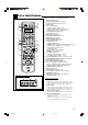
Parts Identification Refer to the pages in parentheses for details.
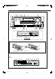
Front Panel 2 345 6 7 1 8 9 p q MASTER VOLUME ZONE 1 ON/OFF SURROUND STANDBY ZONE 2 ON/OFF DSP ZONE 2 CONTROL SURROUND / DSP OFF STANDBY/ON SPEAKERS ON/OFF 1 CC CONVERTER 2 / ZONE 2 DVD MULTI DVD VCR 1 VCR 2 TV SOUND /DBS VIDEO PHONO CD CDR TAPE/MD FM AM SUBWOOFER OUT ON/OFF SETTING ADJUST ANALOG DIRECT MULTI JOG QUICK SPEAKER SETUP EXIT PUSH – OPEN PUSH SET PHONES w tyu r e EX / ES / PL x MIDNIGHT MODE INPUT ANALOG INPUT DIGITAL FM/AM TUNING FM/AM PRESET FM MOD
Refer to the pages in parentheses for details.
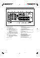
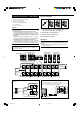
Rear Panel 1 3 2 SUBWOOFER CENTER RIGHT VIDEO LEFT S-VIDEO SURR BACK DVD IN DVD IN DIGITAL 1 (DVD) TV SOUND / DBS IN OUT (REC) DIGITAL 2 (CD) DIGITAL 3 (TV) 2 AM LOOP TAPE / MD R DBS (VCR1) IN IN (PLAY) OUT (REC) CDR VCR 2 ANTENNA COMPULINK-4 (SYNCHRO) SUBWOOFER VCR 1 AV COMPULINKY CAUTION : SPEAKER IMPEDANCE 8 PB PR 16 CAUTION : SPEAKER IMPEDANCE FM 75 COAXIAL + + FRONT1 OR FRONT2 : 8 16 ZONE2 : 8 16 FRONT1 AND FRONT2 : 16 32 1 SPEAKER IN (PLAY) IN (PLAY) PCM/ DOLB
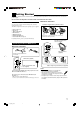
Getting Started This section explains how to connect audio/video components and speakers to the receiver, and how to connect the power supply. Do not connect the AC power cord until all other connections have been made. Checking the Supplied Accessories Check to be sure you have all of the following items, which are supplied for the receiver. The number in parentheses indicates the quantity of pieces supplied.
Connecting the Speakers and Subwoofer Speaker connections 1 You can connect the following speakers: • Two pairs of front speakers. • One pair of surround speakers. • One pair of surround back speakers. • One center speaker. • One powered subwoofer. 4 3 2 RIG FR RIG HT ON FR T1 SP EA LE KE RIG HT ON FT FR T1 SP EA RS LE KE HT ON FT T1 SP RS EA LE KE FT RS CAUTION: • Use only the speakers of the SPEAKER IMPEDANCE indicated by the speaker terminals.
Zone 1 speaker layout Ideal speaker layout varies depending on the conditions of your listening room. The diagram below is a recommended typical example. Subwoofer Enhance your audio system You can use this receiver as the pre-amplifier (control amplifier) when you connect power amplifiers to the PREOUT jacks on the rear panel, using cables with RCA pin plugs (not supplied). • Connect the white plug to the audio left jack, and the red plug to the audio right jack.
Connecting Audio/Video Components CD player When connecting individual components, refer also to the manuals supplied with them. Analog connections If your audio components have digital audio output terminal, connecting them using the digital cords explained in “Digital connections” (see page 14). Audio component connections Use the cables with RCA pin plugs (not supplied). • Connect the white plug to the audio left jack, and the red plug to the audio right jack.
Cassette deck You can connect either a cassette deck or an MD recorder to the TAPE/MD jacks. When connecting an MD recorder, see below. Cassette deck To audio input To audio output Right / Left R L OUT (REC) TAPE / MD L IN (PLAY) R MD recorder You can connect either an MD recorder or a cassette deck to the TAPE/MD jacks. When connecting a cassette deck, see above. Video component connections Use the cables with RCA pin plugs (not supplied).
VCR(s) TV and/or DBS tuner You can connect two VCRs—one to the VCR 1 jacks and the other to the VCR 2 jacks. • If your VCR has an AV COMPU LINK jack, connect it to the VCR 1 jacks so that you can use the AV COMPU LINK remote control system.
DVD player To enjoy Dolby Digital and DTS multi-channel software (including Dual Mono software), connect the DVD player through the digital or analog discrete (DVD MULTI) terminals. • When you connect a DVD player with stereo output jacks: COMPONENT VIDEO • When you connect a DVD player with its analog discrete output (5.1-channel reproduction) jacks: This connection is the best connection method for enjoying DVD Audio sounds.
Digital output terminal Digital connections This receiver is equipped with four DIGITAL IN terminals on the rear panel—one digital coaxial terminal and three digital optical terminals—and one DIGITAL OUT (optical) terminal on the rear panel. Another digital optical input terminal is located on the front panel (see page 11). You can connect any digital components which have an optical digital input terminal.
Connecting the Power Cord Notes: • The signal-reachable distance may differ depending on the operating conditions and circumstances. To improve transmitting conditions, change the distance to the receiver and the direction to transmit while operating the remote control. • To avoid a failure in the reception from the remote control, keep the connecting cables and the IR signal transmitter’s cable away from the RF rod antenna.
Multi-room Operations Before operating this receiver any further, be familiar with this multi-room function. This function enables you to listen to different sources in two different places (we call these two places “Zone 1 (main room)” and “Zone 2 (sub-room)” by using this receiver. This section explains only the required speaker connections, the concept, and basic operations of the multi-room function. For more detailed operations, see the respective pages in this manual.
Basic Operating Procedure for Zone 1 On the front panel: On the remote control: 1 2 4 1 2 3 3 1. Press STANDBY/ON. The STANDBY lamp goes off, and the ZONE 1 indicator lights up on the display. The buttons and controls on the unit work for Zone 1 operations. • For more details, see “Turning the Power On and Off (Standby)” on page 19. The last Zone 1 source appears. The ZONE 1 indicator lights up. 4 1. Set ZONE 1/ZONE 2 selector to ZONE 1.
Basic Operating Procedure for Zone 2 The sources and functions available for Zone 2 operations are limited. For more details on Zone 2 operations, see “Zone 2 (Sub-room) Operations” on pages 26 to 29. On the remote control: When operating the receiver using the remote control, the unit’s display always shows the Zone 1 source information though you are operating it for the Zone 2 source. 1 2 On the front panel: 1 5 2 3 1. Press 4 3 STANDBY/ON.
Zone 1 (Main Room) Operations This section explains only the operations commonly used when you play any sound source in Zone 1 (main room). See pages 26 to 29 for the Zone 2 (sub-room) operations. • Before performing Zone 1 operations, it is recommended to finish the basic settings on pages 32 to 38. On the remote control: IMPORTANT: Check the following before or while using the buttons and controls. For Zone 1 operations: AUDIO POWER The ZONE 1 indicator lights up on the unit’s display.
Speaker and signal indicators on the display Selecting the Zone 1 Source to Play By checking the following indicators, you can easily confirm which speakers you are activating and which signals are coming into this receiver. Speaker indicators L C R Signal indicators L C SUBWFR LFE Press one of the source selection buttons. • When you have connected digital source components using the digital terminals, change the input mode for these components to the digital input mode (see page 22).
Selecting different sources for picture and sound While watching pictures from a video source (DVD player, VCR, or DBS tuner), you can listen to sound of an audio source. • Once you have selected a video source, pictures of the selected source are sent to the TV until you select another video source. Press one of the audio source selection buttons—PHONO, CD, TAPE/MD, CDR, FM, AM—while viewing the picture from a video component such as the VCR or DVD player, etc.
Turning On and Off the Subwoofer Sound Remote NOT You can cancel the subwoofer sound output even though you have connected a subwoofer and have set “SUB WOOFER” to “YES” (see page 34). 2. Press INPUT DIGITAL to select “DGTL AUTO.” • When using the remote control, press ANALOG/DIGITAL. Each time you press the button, the analog (ANALOG) and digital (DGTL AUTO) input modes alternate. The DIGITAL AUTO indicator lights up on the display.
Setting the Dynamic Range Turning Analog Direct On and Off You can enjoy a powerful sound at night using Midnight Mode. You can enjoy the sound closer to the original source by overriding the sound adjustments such as Midnight Mode (see the left column), Bass Boost (see page 24), Equalization pattern (see page 40), speaker output level adjustments (see page 40), and Surround and DSP modes (see pages 42 to 49).
Remote NOT Changing the Source Name The following basic operations are possible only using the remote control. When you have connected an MD recorder to the TAPE/MD IN jacks or a DBS tuner to the TV SOUND/DBS IN jacks on the rear panel, change the source name which will appear on the display. Reinforcing the Bass BASS BOOST Using the Sleep Timer SLEEP DIMMER Changing the Display Brightness MUTING When changing the source name from “TV” to “DBS”: Muting the Sound 1. Press TV SOUND/DBS.
Using the Sleep Timer Recording a source Using the Sleep Timer, you can fall asleep while listening to music. When the shut-off time comes, the receiver turns off automatically. • Sleep Timer works only for the Zone 1 source. Press SLEEP repeatedly. The SLEEP indicator lights up on the unit’s display, and the shut-off time changes in 10-minute intervals: 10 20 30 40 50 60 70 80 90 OFF (Canceled) When the shut-off time comes The receiver turns off automatically.
Zone 2 (Sub-room) Operations This section explains only the operations used when you play a sound source in Zone 2 (sub-room). See pages 19 to 25 for the Zone 1 (main room) operations. • Before performing the Zone 2 operations, it is recommended to finish the basic settings on pages 32 to 38. IMPORTANT: Check the following before or while using the buttons and controls.
To turn off the power (into standby mode), STANDBY/ON again. press The STANDBY lamp lights up. Canceling the Zone 2 Operations On the front panel: On the remote control: AUDIO POWER ZONE 1 ZONE 1 ZONE 2 STANDBY ON ZONE 2 ZONE 2 1. Set ZONE 1/ZONE 2 selector to ZONE 2. Now the buttons on the remote control work for Zone 2 operations. To stop Zone 2 operations and sounds from the Zone 2 speakers, press ZONE 2 ON/OFF so that the ZONE 2 indicator goes off from the display.
Selecting the Zone 2 Source to Play Adjusting the Zone 2 Volume Press one of the source selection buttons (except DVD MULTI and TV SOUND). Ex. When DVD is selected as the source. On the front panel: To increase the volume, turn MASTER VOLUME clockwise. To decrease the volume, turn it counterclockwise. On the remote control: LINEAR PCM SPEAKERS 1 ZONE 2 VOLUME ZONE 1 To increase the volume, press VOLUME +. To decrease the volume, press VOLUME –.
Activating the Zone 2 Front Speakers Remote NOT The following operations are NOT applicable to those who connect the Zone 2 front speakers through the ZONE 2 PREOUT jacks through another amplifier (see page 16). Before you start, remember... When shipped from the factory, both pairs of the front speakers have been set to be used in Zone 1. • To use the speakers connected to the FRONT2/ZONE2 SPEAKERS terminals, set the speaker usage correctly. (See “Setting the Zone 2/Speakers 2 usage” on page 38.
Receiving Radio Broadcasts You can browse through all the stations or use the preset function to go immediately to a particular station. Indicates the functions YOU CAN ALSO USE when the receiver is ready for Zone 2 operations. Tuning in to Stations Manually IMPORTANT: Check the following before or while using the buttons and controls. For Zone 1 operations: The ZONE 1 indicator lights up on the unit’s display. For Zone 2 operations: The ZONE 2 indicator lights up on the unit’s display.
On the remote control: Using Preset Tuning 1. Press FM or AM to select the band. The last received station of the selected band is tuned in. 2. Press the 10 keys to select a preset channel number. Once a station is assigned to a channel number, the station can be quickly tuned in. You can preset up to 30 FM and 15 AM stations. • • • • For channel number 5, press 5. For channel number 15, press +10 then 5. For channel number 20, press +10 then 10. For channel number 30, press +10, +10, then 10.
Basic Settings Some of the following settings are required after connecting and positioning your speakers while others will make operations easier. You can use QUICK SPEAKER SETUP to easily set up your speaker configuration. Basic setting operations are only possible while the receiver is ready for Zone 1 operations. IMPORTANT: 3. Press in MULTI JOG (PUSH SET). Check the following before or while using the buttons and controls.
Speakers (channels) number and the size You can find how each of the speaker size is defined according to the number of connected speakers (speaker channel “CH” number) you select. • Subwoofer is counted as 0.1 channel. The size of connected speakers CH L/R C LS/RS SB SUBWFR 2.0CH LARGE NONE NONE NONE NO 2.1CH SMALL NONE NONE NONE YES 3.0CH LARGE SMALL NONE NONE NO 3.1CH SMALL SMALL NONE NONE YES 4.0CH LARGE NONE SMALL NONE 4.1CH SMALL NONE SMALL 5.
Remote NOT Basic Procedure : shows the initial setting in the following tables. Setting the speakers Before you start, remember... There is a time limit in doing the following steps. If the setting is canceled before you finish, start from step 1 again. 1. Press SETTING. The last selected item appears on the display. ANALOG R VOLUME ZONE 1 Select when a subwoofer is connected. SUB WOOFER: NO Select when no subwoofer is used.
Setting the speaker distance Setting the bass sounds The distance from your listening point to the speakers is another important element to obtain the best possible sound of the Surround and DSP modes. Set the distance from your listening point to the speakers. By referring to the speaker distance setting, this unit automatically sets the delay time of the sound through each speaker so that sounds through all the speakers can reach you at the same time.
7 Crossover frequency—CROSS OVER You can select the crossover frequency for the small speakers used. The signals below the selected frequency level will be sent to and be reproduced by the subwoofer (or by “LARGE” speakers when you have selected “SUB WOOFER: NO”). Selecting the main or sub-channel You can select the playback sound (channel) you want while playing digital software recorded (or broadcast) in the Dual Mono mode (see page 43), which includes two monaural channels separately.
Setting the digital input terminals When you use the digital input terminals, register which components you have connected to the digital input terminals. 7 Digital coaxial terminal—DGTL IN COAX Set the component connected to the digital coaxial terminal (DIGITAL 1). Following setting is available: • DVD (initial setting) • CD • TV (or DBS*1) • CDR • MD • VCR*2 Set the components connected to the digital optical terminals (DIGITAL 2 – 4).
Setting the component video input Setting the Zone 2/Speakers 2 When you use the component video inputs for connecting the DVD player and/or DBS tuner (or VCR), register the type of input jacks. If you have not selected appropriate video input jacks, the AV COMPU LINK remote control system cannot operate properly (See page 53) and you cannot see playback picture of those video components. You can select the usage of the speaker connected to the FRONT2/ZONE2 SPEAKERS terminals.
Adjusting Sound You can make sound adjustment to your preference after completing basic setting. Sound adjustment operations are only possible while the receiver is ready for Zone 1 operations. Basic Adjustment Items IMPORTANT: Check the following before or while using the buttons and controls. On the following pages, you can adjust the items listed below: • You can adjust only the items applicable to the current sound mode.
Basic Procedure Adjusting the equalization patterns You can adjust the equalization patterns to your preference. • Once you have made an adjustment, it is memorized for each source. • The equalization pattern affects the front speaker sounds only. 7 Equalization adjustment—EQ 63Hz, EQ250Hz, EQ 1kHz, EQ 4kHz, EQ16kHz Before you start, remember... There is a time limit in doing the following steps. If the setting is canceled before you finish, start from step 1 again.
Adjusting the sound parameters for the Surround and DSP modes You can adjust the Surround and DSP sound parameters to your preference. (For Surround and DSP modes, see pages 42 to 49.) You can also use the remote control for adjusting the speaker output level and DSP (DAP modes and Mono Film) effect levels (“EFFECT” and “LIVENESS”).
Using the Surround Modes This unit can activates a variety of Surround modes. The basic settings and adjustments stored (see pages 32 to 41) are applied. • The following operations are only possible when the receiver is ready for Zone 1 operations, and are used only for Zone 1 sources. Reproducing Theater Ambience In a movie theater, many speakers are located on the walls to reproduce impressive multi-surround sounds, reaching you from all directions.
Dolby Digital EX DTS Neo:6 Dolby Digital EX (DOLBY D EX) is a digital surround encoding format that adds the third surround channels, called “surround back.” Compared to the conventional Dolby Digital 5.1CH, these newly added surround back channels can reproduce more detailed movements behind you while viewing the video software. In addition, surround sound localization will become more stable. • You can use Virtual 6.
2. Press SURROUND to activate the Surround mode. Activating the Surround Modes Available Surround modes vary depending on the speaker settings and the incoming signals. (See pages 46 and 47.) • For multi-channel digital software, incoming signals are automatically detected and the appropriate Surround mode is activated (see pages 46 and 47 for details). Activating one of the Surround modes for a source automatically recalls the memorized settings and adjustments (see pages 32 to 41).
Activating the EX/ES/PLIIx setting For multi-channel digital software, you can activate the EX/ES/PLIIx (6.1-channel) reproduction mode. • Once you have set EX/ES/PLIIx (6.1-channel) reproduction mode, it is stored in memory and will be called up whenever you activate the Surround mode which the memorized EX/ES/PLIIx (6.1-channel) reproduction mode can be applied to.
Surround Modes Applicable to the Various Software Available Surround modes vary depending on the speaker settings and the incoming signals. The table below shows the relation of the Surround modes and the incoming signals (with the Zone 2 speakers, surround back speakers, and 6.1-channel reproduction mode setting). • The numbers inside the parentheses following the incoming signal type indicate the number of the front channels and that of the surround channels.
Incoming Signal Type Zone 2 Speakers Surround Back Channel Setting EX/ES/PLIIx Setting Available Surround Mode DTS-ES Discrete 6.1ch Activated Not effective Not effective DTS (3D-PHONIC)*2 Deactivated 2SPK/1SPK AUTO/ON ES DSCRT PLIIx MOVIE DTS + DD EX*3 PLIIx MUSIC DTS + PLIIx MU OFF DTS AUTO/ON/PLIIx MOVIE/ PLIIx MUSIC DTS (VIRTUAL SB)*4 OFF DTS NONE DTS-ES Matrix 6.
Using the DSP Modes This unit can activates a variety of DSP modes. The basic settings and adjustments stored (see pages 32 to 41) are applied. • The following operations are only possible when the receiver is ready for Zone 1 operations, and are used only for Zone 1 sources. Reproducing the Sound Field The sound heard in a concert hall, club, etc. consists of direct sound and indirect sound—early reflections and reflections from behind. Direct sounds reach the listener directly without any reflection.
All channel stereo mode This mode can reproduce a larger stereo sound field using all the connected (and activated) speakers. • If the surround speakers are set to “NONE,” you cannot select “ALL STEREO.” PHONO CD VCR 1 DVD VCR 2 TAPE/MD CDR TV/DBS VIDEO FM AM DSP SURR / DSP OFF Sound reproduced from normal stereo 1. Select and play any source excluding DVD MULTI. • Make sure you have selected the analog or digital input mode correctly. • DSP modes are not valid for DVD MULTI playback mode. 2.
Using the DVD MULTI Playback Mode This receiver provides the DVD MULTI playback mode for reproducing the analog discrete output mode of the DVD player. • The following operations are only possible when the receiver is ready for Zone 1 operations, and are used only for Zone 1 sources. IMPORTANT: Connection diagram Check the following before or while using the buttons and controls. For Zone 1 operations: The ZONE 1 indicator lights up on the unit’s display.
COMPU LINK Remote Control System The COMPU LINK remote control system allows you to operate JVC’s audio components through the remote sensor on the receiver. • Refer also to the manuals supplied with your audio components. To use this remote control system, you need to connect JVC’s audio components through the COMPU LINK (SYNCHRO) jacks (see below) in addition to the connections using cables with RCA pin plugs (see pages 10 and 11).
Automatic Power On/Off (Standby)—only possible with the COMPU LINK-3 and COMPU LINK-4 The CD player, CD recorder, and Cassette deck (or MD recorder) turn on and off along with the receiver. Synchronized Recording (Only for Zone 1 Operations) This operation is only possible when the receiver is ready for Zone 1 operations. Synchronized recording means the cassette deck (or MD recorder) starts recording as soon as a CD begins playing.
AV COMPU LINK Remote Control System This receiver is equipped with the AV COMPU LINK-III. The AV COMPU LINK remote control system allows you to operate JVC video components (VCR, DVD player, and TV) through the receiver. To use this remote control system, you need to connect the video components you want to operate, following the procedure below. • Refer also to the manuals supplied with your video components. 1.
CONNECTIONS 3: Video Cable Connection This receiver is equipped with three types of the video terminals—S-video, composite video, and component video, and can output the signal through the output jack only the signal came from same type input jack.
One-Touch DVD Play Simply by starting playback on the DVD player, you can enjoy the DVD playback without setting other switches manually. Automatic Power On/Off (Standby) The TV (for Zone 1 only), VCR 1 (VCR connected to the VCR 1 jacks), and DVD player turn on and off along with the receiver.
Operating JVC’s Audio/Video Components You can operate JVC’s audio and video components with this receiver’s remote control, since control signals for JVC components are preset in the remote control. • Refer also to the manuals supplied with your video components.
CD player After pressing CD, you can perform the following operations on the CD player: PLAY : Start playing. 4 : Return to the beginning of the current (or previous) track. ¢ : Skip to the beginning of the next track. STOP : Stop playing. PAUSE : Pause playing. To resume, press PLAY. 1 – 10, +10 : Select a track number directly. For track number 5, press 5. For track number 15, press +10, then 5. For track number 20, press +10, then 10. For track number 30, press +10, +10, then 10.
VCR (connected to the VCR 1 jacks) Operating Video Components After pressing VCR 1 or selecting “VCR1” by pressing CONTROL repeatedly, you can perform the following operations on the VCR: IMPORTANT: To operate JVC’s video components using this remote control: • You need to connect JVC’s video components through the AV COMPU LINK jacks (see page 53) in addition to the connections using cables with RCA pin plugs (see pages 12 and 13).
Operating Other Manufacturers’ Equipment This remote control supplied with the receiver can transmit control signals for other manufacturers’ TVs, CATV converters, DBS tuners, VCRs and DVD players. • Refer also to the manuals supplied with your video components. IMPORTANT: • To operate the other component(s) using the RF signals emitted from this remote control, the IR signal transmitter and the RF rod antenna must be connected to this receiver.
To change the transmittable signals for operating another manufacturer’s VCR To change the transmittable signals for operating another manufacturer’s CATV converter or DBS tuner 1. Press and hold DVD POWER. 1. Set the TV operation mode selector to CATV/DBS. DVD 2. Press VCR 1. POWER TV/CATV/DBS POWER 3. Enter a manufacturer’s code using buttons 1–9, and 0. 2. Press and hold TV/CATV/DBS POWER. See page 62 to find the code. 3. Press TV/DBS. 4. Release DVD POWER. TV/DBS 4.
To change the transmittable signals for operating another manufacturer’s DVD player To change the transmittable signals for operating another manufacturer’s CD player 1. Press and hold DVD POWER. 1. Press and hold AUDIO POWER ON. 2. Press DVD. AUDIO POWER ON DVD POWER 2. Press CD. 3. Enter a manufacturer’s code using buttons 1–9, and 0. 3. Enter a manufacturer’s code using buttons 1–9, and 0. DVD See page 62 to find the code. CD See page 62 to find the code. 4. Release DVD POWER. 1 2 4 5.
For TV Manufacturer JVC Fisher Sanyo Hitachi Magnavox Mitsubishi RCA/PROSC Samsung Philips Panasonic Toshiba Sharp Sony Zenith Mets Quelle For VCR Codes 00*, 14, 74 05 05 08, 09, 10, 49 08, 17, 49 08, 18 08, 24, 29, 30, 31, 48 08, 34, 49 17 24, 26, 76 37, 43 38, 77 39 45, 46 50, 51, 52, 53 52, 53, 54, 55, 56, 57, 58, 59, 60, 61, 62, 63, 64, 65, 66, 67 For CATV converter Manufacturer Manufacturer JVC Aiwa Funai Bell & Howell Fisher Sanyo Magnavox RCA/PROSC Goldstar Emerson GE Hitachi Panasonic Philips NE
Troubleshooting Use this chart to help you solve daily operational problems. If there is any problem you cannot solve, contact your JVC‘s service center. POSSIBLE CAUSE SOLUTION The buttons and controls on the front panel do not work. The multi-room function is not set correctly. • Press ZONE 1 ON/OFF for Zone 1 operations. • Press ZONE 2 ON/OFF and ZONE 2 CONTROL for Zone 2 operations. No sound from the speakers in Zone 1. Speaker signal cables are not connected properly.
SOLUTION Multi-channel reproduction mode cannot be used for Zone 1 sources. ZONE 2 SPEAKERS are activated. Deactivate the Zone 2 front speakers. Expected surround effect cannot be obtained. Speakers are deactivated on the Quick Speaker Setup or the Basic Setting. Activate all connected speakers correctly. (See “Setting the speakers” on page 34.) No sound effect such as the Surround mode, DSP mode and equalization pattern. Analog Direct is turned on. Turn off Analog Direct. (See page 23.
Specifications Amplifier Output Power At Stereo Operation Front Channel: 130 W per channel, min. RMS, driven into 8 Ω, 20 Hz to 20 kHz, with no more than 0.08% total harmonic distortion. At Surround Operation Front Channel: 130 W per channel, min. RMS, driven into 8 Ω at 1 kHz, with no more than 0.8% total harmonic distortion. Center Channel: 130 W, min. RMS, driven into 8 Ω at 1 kHz, with no more than 0.8% total harmonic distortion. Surround Channel: 130 W per channel, min.
LIMITED WARRANTY AUDIO-2 JVC COMPANY OF AMERICA warrants this product and all parts thereof, except as set forth below ONLY TO THE ORIGINAL PURCHASER AT RETAIL to be FREE FROM DEFECTIVE MATERIALS AND WORKMANSHIP from the date of original retail purchase for the period as shown below. ("The Warranty Period") PARTS 2 LABOR YRS 2 YRS THIS LIMITED WARRANTY IS VALID ONLY IN THE FIFTY (50) UNITED STATES, THE DISTRICT OF COLUMBIA AND IN COMMONWEALTH OF PUERTO RICO.
Authorized Service Centers ® QUALITY SERVICE HOW TO LOCATE YOUR JVC SERVICE CENTER TOLL FREE: 1 (800) 537-5722 http://www.jvc.com Dear Customer, In order to receive the most satisfaction from your purchase,please read the instruction booklet before operating the unit.In the event that repairs are necessary, please call 1 (800)537-5722 for your nearest authorized servicer or visit our website at www.JVC.com Remember to retain your Bill of Sale for Warranty Service.
RX-8040B AUDIO/VIDEO CONTROL RECEIVER VICTOR COMPANY OF JAPAN, LIMITED EN © 2004 VICTOR COMPANY OF JAPAN, LIMITED Cover_8040[J]_D.p65 2 0404MWMMDWJEIN 04.4.
English Français AUDIO/VIDEO CONTROL RECEIVER RECEPTEUR DE COMMANDE AUDIO/VIDEO RX-8040B INSTRUCTIONS MANUEL D’INSTRUCTIONS LVT1198-002A [C] Cover_8040[C].p65 1 04.5.
Warnings, Cautions and Others/ Mises en garde, précautions et indications diverses CAUTION RISK OF ELECTRIC SHOCK DO NOT OPEN CAUTION: TO REDUCE THE RISK OF ELECTRIC SHOCK. DO NOT REMOVE COVER (OR BACK) NO USER SERVICEABLE PARTS INSIDE. REFER SERVICING TO QUALIFIED SERVICE PERSONNEL.
English Introduction We would like to thank you for purchasing one of our JVC products. Before operating this unit, read this manual carefully and thoroughly to obtain the best possible performance from your unit, and retain this manual for future reference.
English Table of Contents Parts Identification ...................................... 3 Basic Settings ........................................... 32 Getting Started ........................................... 7 Quick Speaker Setup ................................................................ 32 Basic Setting Items ................................................................... 33 Basic Procedure ........................................................................ 34 Setting the speakers ....
Refer to the pages in parentheses for details.
English Front Panel 2 345 6 7 1 8 9 p q MASTER VOLUME ZONE 1 ON/OFF SURROUND STANDBY ZONE 2 ON/OFF DSP ZONE 2 CONTROL SURROUND / DSP OFF STANDBY/ON SPEAKERS ON/OFF 1 CC CONVERTER 2 / ZONE 2 DVD MULTI DVD VCR 1 VCR 2 TV SOUND /DBS VIDEO PHONO CD CDR TAPE/MD FM AM SUBWOOFER OUT ON/OFF SETTING ADJUST ANALOG DIRECT MULTI JOG QUICK SPEAKER SETUP EXIT PUSH – OPEN PUSH SET PHONES w tyu r e EX / ES / PL x MIDNIGHT MODE INPUT ANALOG INPUT DIGITAL FM/AM TUNING FM/AM PRES
English Refer to the pages in parentheses for details.
English Rear Panel 1 3 2 SUBWOOFER CENTER RIGHT VIDEO LEFT S-VIDEO SURR BACK DVD IN DVD IN DIGITAL 1 (DVD) TV SOUND / DBS IN OUT (REC) DIGITAL 2 (CD) DIGITAL 3 (TV) 2 AM LOOP TAPE / MD R DBS (VCR1) IN IN (PLAY) OUT (REC) CDR VCR 2 ANTENNA COMPULINK-4 (SYNCHRO) SUBWOOFER VCR 1 AV COMPULINKY CAUTION : SPEAKER IMPEDANCE 8 PB PR 16 CAUTION : SPEAKER IMPEDANCE FM 75 COAXIAL + + FRONT1 OR FRONT2 : 8 16 ZONE2 : 8 16 FRONT1 AND FRONT2 : 16 32 1 SPEAKER IN (PLAY) IN (PLAY)
English Getting Started This section explains how to connect audio/video components and speakers to the receiver, and how to connect the power supply. Do not connect the AC power cord until all other connections have been made. Checking the Supplied Accessories Check to be sure you have all of the following items, which are supplied for the receiver. The number in parentheses indicates the quantity of pieces supplied.
English Connecting the Speakers and Subwoofer Speaker connections 1 You can connect the following speakers: • Two pairs of front speakers. • One pair of surround speakers. • One pair of surround back speakers. • One center speaker. • One powered subwoofer. 4 3 2 RIG RIG HT RIG HT T1 ON ON ON SP LE EA KE T1 FT HT FR FR FR SP LE EA KE RS T1 FT SP LE EA RS KE FT RS CAUTION: • Use only the speakers of the SPEAKER IMPEDANCE indicated by the speaker terminals.
Enhance your audio system You can use this receiver as the pre-amplifier (control amplifier) when you connect power amplifiers to the PREOUT jacks on the rear panel, using cables with RCA pin plugs (not supplied). • Connect the white plug to the audio left jack, and the red plug to the audio right jack.
English Connecting Audio/Video Components CD player When connecting individual components, refer also to the manuals supplied with them. Analog connections If your audio components have digital audio output terminal, connecting them using the digital cords explained in “Digital connections” (see page 14). Audio component connections Use the cables with RCA pin plugs (not supplied). • Connect the white plug to the audio left jack, and the red plug to the audio right jack.
Cassette deck To audio input To audio output Right / Left R L OUT (REC) TAPE / MD L IN (PLAY) R MD recorder You can connect either an MD recorder or a cassette deck to the TAPE/MD jacks. When connecting a cassette deck, see above. Video component connections Use the cables with RCA pin plugs (not supplied). Connect the white plug to the audio left jack, the red plug to the audio right jack, and the yellow plug to the video jack.
English VCR(s) TV and/or DBS tuner You can connect two VCRs—one to the VCR 1 jacks and the other to the VCR 2 jacks. • If your VCR has an AV COMPU LINK jack, connect it to the VCR 1 jacks so that you can use the AV COMPU LINK remote control system.
English DVD player To enjoy Dolby Digital and DTS multi-channel software (including Dual Mono software), connect the DVD player through the digital or analog discrete (DVD MULTI) terminals. • When you connect a DVD player with stereo output jacks: COMPONENT VIDEO • When you connect a DVD player with its analog discrete output (5.1-channel reproduction) jacks: This connection is the best connection method for enjoying DVD Audio sounds.
English Digital output terminal Digital connections This receiver is equipped with four DIGITAL IN terminals on the rear panel—one digital coaxial terminal and three digital optical terminals—and one DIGITAL OUT (optical) terminal on the rear panel. Another digital optical input terminal is located on the front panel (see page 11). You can connect any digital components which have an optical digital input terminal.
• The signal-reachable distance may differ depending on the operating conditions and circumstances. To improve transmitting conditions, change the distance to the receiver and the direction to transmit while operating the remote control. • To avoid a failure in the reception from the remote control, keep the connecting cables and the IR signal transmitter’s cable away from the RF rod antenna. Setting up the IR signal transmitter The IR signal transmitter can retransmit the IR signals.
English Multi-room Operations Before operating this receiver any further, be familiar with this multi-room function. This function enables you to listen to different sources in two different places (we call these two places “Zone 1 (main room)” and “Zone 2 (sub-room)”) by using this receiver. This section explains only the required speaker connections, the concept, and basic operations of the multi-room function. For more detailed operations, see the respective pages in this manual.
On the front panel: English Basic Operating Procedure for Zone 1 On the remote control: 1 2 4 1 2 3 3 1. Press STANDBY/ON. The STANDBY lamp goes off, and the ZONE 1 indicator lights up on the display. The buttons and controls on the unit work for Zone 1 operations. • For more details, see “Turning the Power On and Off (Standby)” on page 19. The last Zone 1 source appears. The ZONE 1 indicator lights up. 4 1. Set ZONE 1/ZONE 2 selector to ZONE 1.
English Basic Operating Procedure for Zone 2 The sources and functions available for Zone 2 operations are limited. For more details on Zone 2 operations, see “Zone 2 (Sub-room) Operations” on pages 26 to 29. On the remote control: When operating the receiver using the remote control, the unit’s display always shows the Zone 1 source information though you are operating it for the Zone 2 source. 1 2 On the front panel: 1 5 2 3 1. Press 4 3 STANDBY/ON.
English Zone 1 (Main Room) Operations This section explains only the operations commonly used when you play any sound source in Zone 1 (main room). See pages 26 to 29 for the Zone 2 (sub-room) operations. • Before performing Zone 1 operations, it is recommended to finish the basic settings on pages 32 to 38. On the remote control: IMPORTANT: Check the following before or while using the buttons and controls. For Zone 1 operations: AUDIO POWER The ZONE 1 indicator lights up on the unit’s display.
English Speaker and signal indicators on the display Selecting the Zone 1 Source to Play By checking the following indicators, you can easily confirm which speakers you are activating and which signals are coming into this receiver. Speaker indicators L C R Signal indicators L C SUBWFR LFE Press one of the source selection buttons. • When you have connected digital source components using the digital terminals, change the input mode for these components to the digital input mode (see page 22).
English Selecting different sources for picture and sound While watching pictures from a video source (DVD player, VCR, or DBS tuner), you can listen to sound of an audio source. • Once you have selected a video source, pictures of the selected source are sent to the TV until you select another video source. Press one of the audio source selection buttons—PHONO, CD, TAPE/MD, CDR, FM, AM—while viewing the picture from a video component such as the VCR or DVD player, etc.
English Turning On and Off the Subwoofer Sound Remote NOT You can cancel the subwoofer sound output even though you have connected a subwoofer and have set “SUB WOOFER” to “YES” (see page 34). 2. Press INPUT DIGITAL to select “DGTL AUTO.” • When using the remote control, press ANALOG/DIGITAL. Each time you press the button, the analog (ANALOG) and digital (DGTL AUTO) input modes alternate. The DIGITAL AUTO indicator lights up on the display.
Turning Analog Direct On and Off You can enjoy a powerful sound at night using Midnight Mode. You can enjoy the sound closer to the original source by overriding the sound adjustments such as Midnight Mode (see the left column), Bass Boost (see page 24), Equalization pattern (see page 40), speaker output level adjustments (see page 40), and Surround and DSP modes (see pages 42 to 49). You can only adjust the volume level and the subwoofer output level while Analog Direct is in use.
English Remote NOT Changing the Source Name The following basic operations are possible only using the remote control. When you have connected an MD recorder to the TAPE/MD IN jacks or a DBS tuner to the TV SOUND/DBS IN jacks on the rear panel, change the source name which will appear on the display. Reinforcing the Bass BASS BOOST Using the Sleep Timer SLEEP DIMMER Changing the Display Brightness MUTING When changing the source name from “TV” to “DBS”: Muting the Sound 1. Press TV SOUND/DBS.
Recording a source Using the Sleep Timer, you can fall asleep while listening to music. When the shut-off time comes, the receiver turns off automatically. • Sleep Timer works only for the Zone 1 source. Press SLEEP repeatedly. The SLEEP indicator lights up on the unit’s display, and the shut-off time changes in 10-minute intervals: 10 20 30 40 50 60 70 80 90 OFF (Canceled) When the shut-off time comes The receiver turns off automatically.
English Zone 2 (Sub-room) Operations This section explains only the operations used when you play a sound source in Zone 2 (sub-room). See pages 19 to 25 for the Zone 1 (main room) operations. • Before performing the Zone 2 operations, it is recommended to finish the basic settings on pages 32 to 38. IMPORTANT: Check the following before or while using the buttons and controls.
English To turn off the power (into standby mode), STANDBY/ON again. press The STANDBY lamp lights up. Canceling the Zone 2 Operations On the front panel: On the remote control: AUDIO POWER ZONE 1 ZONE 1 ZONE 2 STANDBY ON ZONE 2 ZONE 2 1. Set ZONE 1/ZONE 2 selector to ZONE 2. Now the buttons on the remote control work for Zone 2 operations. To stop Zone 2 operations and sounds from the Zone 2 speakers, press ZONE 2 ON/OFF so that the ZONE 2 indicator goes off from the display.
English Selecting the Zone 2 Source to Play Adjusting the Zone 2 Volume Press one of the source selection buttons (except DVD MULTI and TV SOUND). Ex. When DVD is selected as the source. On the front panel: To increase the volume, turn MASTER VOLUME clockwise. To decrease the volume, turn it counterclockwise. On the remote control: LINEAR PCM SPEAKERS 1 ZONE 2 VOLUME ZONE 1 To increase the volume, press VOLUME +. To decrease the volume, press VOLUME –.
Remote NOT The following operations are NOT applicable to those who connect the Zone 2 front speakers through the ZONE 2 PREOUT jacks through another amplifier (see page 16). Before you start, remember... When shipped from the factory, both pairs of the front speakers have been set to be used in Zone 1. • To use the speakers connected to the FRONT2/ZONE2 SPEAKERS terminals, set the speaker usage correctly. (See “Setting the Zone 2/Speakers 2 usage” on page 38.
English Receiving Radio Broadcasts You can browse through all the stations or use the preset function to go immediately to a particular station. Indicates the functions YOU CAN ALSO USE when the receiver is ready for Zone 2 operations. Tuning in to Stations Manually IMPORTANT: Check the following before or while using the buttons and controls. For Zone 1 operations: The ZONE 1 indicator lights up on the unit’s display. For Zone 2 operations: The ZONE 2 indicator lights up on the unit’s display.
English On the remote control: Using Preset Tuning 1. Press FM or AM to select the band. The last received station of the selected band is tuned in. 2. Press the 10 keys to select a preset channel number. Once a station is assigned to a channel number, the station can be quickly tuned in. You can preset up to 30 FM and 15 AM stations. • • • • For channel number 5, press 5. For channel number 15, press +10 then 5. For channel number 20, press +10 then 10.
English Basic Settings Some of the following settings are required after connecting and positioning your speakers while others will make operations easier. You can use QUICK SPEAKER SETUP to easily set up your speaker configuration. Basic setting operations are only possible while the receiver is ready for Zone 1 operations. IMPORTANT: 3. Press in MULTI JOG (PUSH SET). Check the following before or while using the buttons and controls.
The size of connected speakers CH L/R C LS/RS SB SUBWFR 2.0CH LARGE NONE NONE NONE NO 2.1CH SMALL NONE NONE NONE YES 3.0CH LARGE SMALL NONE NONE NO 3.1CH SMALL SMALL NONE NONE YES 4.0CH LARGE NONE SMALL NONE 4.1CH SMALL NONE SMALL 5.0CH LARGE SMALL 5.1CH SMALL 6.0CH Remote NOT Basic Setting Items On the following pages, you can adjust the following items: • You can only select the items currently available. For details, see the explanation of each item.
English Remote NOT Basic Procedure : shows the initial setting in the following tables. Setting the speakers Before you start, remember... There is a time limit in doing the following steps. If the setting is canceled before you finish, start from step 1 again. 1. Press SETTING. The last selected item appears on the display. ANALOG R VOLUME ZONE 1 Select when a subwoofer is connected. SUB WOOFER: NO Select when no subwoofer is used.
Setting the bass sounds The distance from your listening point to the speakers is another important element to obtain the best possible sound of the Surround and DSP modes. Set the distance from your listening point to the speakers. By referring to the speaker distance setting, this unit automatically sets the delay time of the sound through each speaker so that sounds through all the speakers can reach you at the same time. • If you have used Quick Speaker Setup on page 32, this setting is not required.
English 7 Crossover frequency—CROSS OVER You can select the crossover frequency for the small speakers used. The signals below the selected frequency level will be sent to and be reproduced by the subwoofer (or by “LARGE” speakers when you have selected “SUB WOOFER: NO”). Selecting the main or sub-channel You can select the playback sound (channel) you want while playing digital software recorded (or broadcast) in the Dual Mono mode (see page 43), which includes two monaural channels separately.
When you use the digital input terminals, register which components you have connected to the digital input terminals. 7 Digital coaxial terminal—DGTL IN COAX Set the component connected to the digital coaxial terminal (DIGITAL 1). Following setting is available: • DVD (initial setting) • CD • TV (or DBS*1) • CDR • MD • VCR*2 Set the components connected to the digital optical terminals (DIGITAL 2 – 4).
English Setting the component video input Setting the Zone 2/Speakers 2 When you use the component video inputs for connecting the DVD player and/or DBS tuner (or VCR), register the type of input jacks. If you have not selected appropriate video input jacks, the AV COMPU LINK remote control system cannot operate properly (see page 53) and you cannot see playback picture of those video components. You can select the usage of the speaker connected to the FRONT2/ZONE2 SPEAKERS terminals.
English Adjusting Sound You can make sound adjustment to your preference after completing basic setting. Sound adjustment operations are only possible while the receiver is ready for Zone 1 operations. Basic Adjustment Items IMPORTANT: Check the following before or while using the buttons and controls. On the following pages, you can adjust the items listed below: • You can adjust only the items applicable to the current sound mode.
English Basic Procedure Adjusting the equalization patterns You can adjust the equalization patterns to your preference. • Once you have made an adjustment, it is memorized for each source. • The equalization pattern affects the front speaker sounds only. 7 Equalization adjustment—EQ 63Hz, EQ250Hz, EQ 1kHz, EQ 4kHz, EQ16kHz Before you start, remember... There is a time limit in doing the following steps. If the setting is canceled before you finish, start from step 1 again.
You can adjust the Surround and DSP sound parameters to your preference. (For Surround and DSP modes, see pages 42 to 49.) You can also use the remote control for adjusting the speaker output level and DSP (DAP modes and Mono Film) effect levels (“EFFECT” and “LIVENESS”). 7 Adjustable parameters You can adjust the following parameters: For Surround and DSP modes (when the center speaker is connected) • This setting is common to all Surround modes, and is memorized separately for DSP modes.
English Using the Surround Modes This unit can activates a variety of Surround modes. The basic settings and adjustments stored (see pages 32 to 41) are applied. • The following operations are only possible when the receiver is ready for Zone 1 operations, and are used only for Zone 1 sources. Reproducing Theater Ambience In a movie theater, many speakers are located on the walls to reproduce impressive multi-surround sounds, reaching you from all directions.
DTS Neo:6 Dolby Digital EX (DOLBY D EX) is a digital surround encoding format that adds the third surround channels, called “surround back.” Compared to the conventional Dolby Digital 5.1CH, these newly added surround back channels can reproduce more detailed movements behind you while viewing the video software. In addition, surround sound localization will become more stable. • You can use Virtual 6.
English 2. Press SURROUND to activate the Surround mode. Activating the Surround Modes Available Surround modes vary depending on the speaker settings and the incoming signals. (See pages 46 and 47.) • For multi-channel digital software, incoming signals are automatically detected and the appropriate Surround mode is activated (see pages 46 and 47 for details). Activating one of the Surround modes for a source automatically recalls the memorized settings and adjustments (see pages 32 to 41).
For multi-channel digital software, you can activate the EX/ES/PLIIx (6.1-channel) reproduction mode. • Once you have set EX/ES/PLIIx (6.1-channel) reproduction mode, it is stored in memory and will be called up whenever you activate the Surround mode which the memorized EX/ES/PLIIx (6.1-channel) reproduction mode can be applied to. • Each time you press the button, it changes as follows: For details of applicable Surround mode, see “Surround Modes Applicable to the Various Software” on pages 46 and 47.
English Surround Modes Applicable to the Various Software Available Surround modes vary depending on the speaker settings and the incoming signals. The table below shows the relation of the Surround modes and the incoming signals (with the Zone 2 speakers, surround back speakers, and 6.1-channel reproduction mode setting). • The numbers inside the parentheses following the incoming signal type indicate the number of the front channels and that of the surround channels.
Zone 2 Speakers Surround Back Channel Setting EX/ES/PLIIx Setting Available Surround Mode DTS-ES Discrete 6.1ch Activated Not effective Not effective DTS (3D-PHONIC)*2 Deactivated 2SPK/1SPK AUTO/ON ES DSCRT PLIIx MOVIE DTS + DD EX*3 PLIIx MUSIC DTS + PLIIx MU OFF DTS AUTO/ON/PLIIx MOVIE/ PLIIx MUSIC DTS (VIRTUAL SB)*4 OFF DTS NONE DTS-ES Matrix 6.
English Using the DSP Modes This unit can activates a variety of DSP modes. The basic settings and adjustments stored (see pages 32 to 41) are applied. • The following operations are only possible when the receiver is ready for Zone 1 operations, and are used only for Zone 1 sources. Reproducing the Sound Field The sound heard in a concert hall, club, etc. consists of direct sound and indirect sound—early reflections and reflections from behind.
English All channel stereo mode This mode can reproduce a larger stereo sound field using all the connected (and activated) speakers. • If the surround speakers are set to “NONE,” you cannot select “ALL STEREO.” PHONO CD VCR 1 DVD VCR 2 TAPE/MD CDR TV/DBS VIDEO FM AM DSP SURR / DSP OFF Sound reproduced from normal stereo 1. Select and play any source excluding DVD MULTI. • Make sure you have selected the analog or digital input mode correctly.
English Using the DVD MULTI Playback Mode This receiver provides the DVD MULTI playback mode for reproducing the analog discrete output mode of the DVD player. • The following operations are only possible when the receiver is ready for Zone 1 operations, and are used only for Zone 1 sources. IMPORTANT: Connection diagram Check the following before or while using the buttons and controls. For Zone 1 operations: The ZONE 1 indicator lights up on the unit’s display.
The COMPU LINK remote control system allows you to operate JVC’s audio components through the remote sensor on the receiver. • Refer also to the manuals supplied with your audio components. To use this remote control system, you need to connect JVC’s audio components through the COMPU LINK (SYNCHRO) jacks (see below) in addition to the connections using cables with RCA pin plugs (see pages 10 and 11). • Make sure that the AC power cords of these components are unplugged before connection.
English Automatic Power On/Off (Standby)—only possible with the COMPU LINK-3 and COMPU LINK-4 The CD player, CD recorder, and Cassette deck (or MD recorder) turn on and off along with the receiver. Synchronized Recording (Only for Zone 1 Operations) This operation is only possible when the receiver is ready for Zone 1 operations. Synchronized recording means the cassette deck (or MD recorder) starts recording as soon as a CD begins playing.
This receiver is equipped with the AV COMPU LINK-III. The AV COMPU LINK remote control system allows you to operate JVC video components (VCR, DVD player, and TV) through the receiver. To use this remote control system, you need to connect the video components you want to operate, following the procedure below. • Refer also to the manuals supplied with your video components. 1.
English CONNECTIONS 3: Video Cable Connection This receiver is equipped with three types of the video terminals—S-video, composite video, and component video, and can output the signal through the output jack only the signal came from same type input jack.
Automatic Power On/Off (Standby) The TV (for Zone 1 only), VCR 1 (VCR connected to the VCR 1 jacks), and DVD player turn on and off along with the receiver. When you press PLAY on the remote control supplied for this receiver for operating the DVD player, the receiver automatically turns on and changes the Zone 1 source or Zone 2 source, depending on ZONE 1/ZONE 2 selector setting on the remote control, to the appropriate input—“DVD” or “DVD MULTI” as the Zone 1 source, and “DVD” as the Zone 2 source.
English Operating JVC’s Audio/Video Components You can operate JVC’s audio and video components with this receiver’s remote control, since control signals for JVC components are preset in the remote control. • Refer also to the manuals supplied with your video components.
CD changer After selecting “CDDSC” by pressing CONTROL repeatedly, you can perform the following operations on the CD changer: PLAY : Start playing. 4 : Return to the beginning of the current (or previous) track. ¢ : Skip to the beginning of the next track. STOP : Stop playing. PAUSE : Pause playing. To release, press PLAY. 1 – 6, 7/P : Select the number of a disc installed in the CD changer.
English VCR (connected to the VCR 1 jacks) Operating Video Components After pressing VCR 1 or selecting “VCR1” by pressing CONTROL repeatedly, you can perform the following operations on the VCR: IMPORTANT: To operate JVC’s video components using this remote control: • You need to connect JVC’s video components through the AV COMPU LINK jacks (see page 53) in addition to the connections using cables with RCA pin plugs (see pages 12 and 13).
English Operating Other Manufacturers’ Equipment This remote control supplied with the receiver can transmit control signals for other manufacturers’ TVs, CATV converters, DBS tuners, VCRs and DVD players. • Refer also to the manuals supplied with your video components. IMPORTANT: • To operate the other component(s) using the RF signals emitted from this remote control, the IR signal transmitter and the RF rod antenna must be connected to this receiver.
English To change the transmittable signals for operating another manufacturer’s VCR To change the transmittable signals for operating another manufacturer’s CATV converter or DBS tuner 1. Press and hold DVD POWER. 1. Set the TV operation mode selector to CATV/DBS. DVD 2. Press VCR 1. POWER TV/CATV/DBS POWER 3. Enter a manufacturer’s code using buttons 1–9, and 0. 2. Press and hold TV/CATV/DBS POWER. See page 62 to find the code. 3. Press TV/DBS. 4. Release DVD POWER. TV/DBS 4.
To change the transmittable signals for operating another manufacturer’s CD player 1. Press and hold DVD POWER. 1. Press and hold AUDIO POWER ON. 2. Press DVD. English To change the transmittable signals for operating another manufacturer’s DVD player AUDIO POWER ON DVD POWER 2. Press CD. 3. Enter a manufacturer’s code using buttons 1–9, and 0. 3. Enter a manufacturer’s code using buttons 1–9, and 0. DVD See page 62 to find the code. CD See page 62 to find the code. 4. Release DVD POWER.
English For TV Manufacturer JVC Fisher Sanyo Hitachi Magnavox Mitsubishi RCA/PROSC Samsung Philips Panasonic Toshiba Sharp Sony Zenith Mets Quelle For VCR Codes 00*, 14, 74 05 05 08, 09, 10, 49 08, 17, 49 08, 18 08, 24, 29, 30, 31, 48 08, 34, 49 17 24, 26, 76 37, 43 38, 77 39 45, 46 50, 51, 52, 53 52, 53, 54, 55, 56, 57, 58, 59, 60, 61, 62, 63, 64, 65, 66, 67 For CATV converter Manufacturer Manufacturer JVC Aiwa Funai Bell & Howell Fisher Sanyo Magnavox RCA/PROSC Goldstar Emerson GE Hitachi Panasonic P
Use this chart to help you solve daily operational problems. If there is any problem you cannot solve, contact your JVC‘s service center. POSSIBLE CAUSE SOLUTION The buttons and controls on the front panel do not work. The multi-room function is not set correctly. • Press ZONE 1 ON/OFF for Zone 1 operations. • Press ZONE 2 ON/OFF and ZONE 2 CONTROL for Zone 2 operations. No sound from the speakers in Zone 1. Speaker signal cables are not connected properly.
SOLUTION Multi-channel reproduction mode cannot be used for Zone 1 sources. ZONE 2 SPEAKERS are activated. Deactivate the Zone 2 front speakers. Expected surround effect cannot be obtained. Speakers are deactivated on the Quick Speaker Setup or the Basic Setting. Activate all connected speakers correctly. (See “Setting the speakers” on page 34.) No sound effect such as the Surround mode, DSP mode and equalization pattern. Analog Direct is turned on. Turn off Analog Direct. (See page 23.
Amplifier Output Power At Stereo Operation Front Channel: 130 W per channel, min. RMS, driven into 8 Ω, 20 Hz to 20 kHz, with no more than 0.08% total harmonic distortion. At Surround Operation Front Channel: 130 W per channel, min. RMS, driven into 8 Ω at 1 kHz, with no more than 0.8% total harmonic distortion. Center Channel: 130 W, min. RMS, driven into 8 Ω at 1 kHz, with no more than 0.8% total harmonic distortion. Surround Channel: 130 W per channel, min.
RX-8040B AUDIO/VIDEO CONTROL RECEIVER VICTOR COMPANY OF JAPAN, LIMITED EN, FR © 2004 VICTOR COMPANY OF JAPAN, LIMITED Cover_8040[C].p65 2 0504MWMMDWJEIN 04.5.