JVC AUDIO/VIDEO CONTROL RECEIVER RX-8040B o o o o o o I il I I ] I I I I I I I I _ C_ C3_ '70D_ I Jw OD[N_ DIGITAL. EX "J;[,]1 K,I_ [d ,m_ rr IL_IL_ _=NVE.TE. _ .......... "I_VlVlf PIq_llli)l 1kl kllVl_k I I IILIb III/Remote//ll TRUCTIONS r A,/,",,_n.n. _! _vITIr_ i lair IbllfWBI For Customer Use: Enter below the Model No. and Serial No. which are located either on the rear, bottom or side of the cabinet. Retain this information for future reference. Model No.
Warnings, Cautions and Others/ Mises en garde, precautions et indications diverses CAUTION To reduce the risk of electrical shocks, fire, etc.: 1. Do not remove screws, covers or cabinet. 2. Do not expose this appliance to rain or moisture. CAUTION: REFER TO REDUCE THE RISK OF ELECTRIC SHOCK. DO NOT REMOVE COVER (OR BACK) NO USER SERVICEABLE PARTS INSIDE. SERVICING TO QUALIFIED SERVICE PERSONNEL.
Introduction Before CC (Compression CC Converter reduction We would like to thank you for purchasing one of our JVC products. this unit, read this manual carefully and thoroughly to obtain the best possible performance from your unit, and retain this manual for future reference. operating Compensative) eliminates ill digital jitter and ripples, distortion ill 24 bit-quantization 128 kHz (for fs 32 kHz signals)/176.
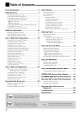
Table of Contents Parts Identification Getting Started ...................................... ........................................... 3 7 Basic Settings Quick Speaker Setup Basic Setting Checking the Supplied Accessories ........................................... 7 ....................................... 7 ................................... 8 Connecting the FM and AM Antennas Connecting the Speakers and Subwoofer Connecting Audio/Video Components • Analog connections .....
Parts Identification Refer to the pages in parentheses Remote Control for details.
Front Panel Inside the front door How to open the front door Display / @ 4
Refer to the pages in parentheses Front 1 _] 7 8 _] 10 _) 12 13 14 15] 1G 17 18 19 20 21 22 23 24] 25 26 for details.
Rear Panel I d II [] Refer 1] to the DIGITAL Coaxial: in parentheses for details.
I Getting Started This section explains how to connect audio/video components and speakers to the receiver, power supply Do not connect the AC power cord until all other connections have been made. [,-],"t'_ _1 Check AM antenna I",h'_][-'-m _r'1 R_,. IL,_ to be sure you have all of the followiug supplied items, which are Assemhle and how to connect the connections the supplied AM loop antenna as follows: for the receiver.
|l_o] i| i[_ _ li[i i _ i[;li'-'] i[_-I You car] connect the following • Two pairs of front speakers. [(;,] I_ll_-Iil il!iYLo[o} _,,a speakers, • One pair of surround back speakers, Speaker connections 1 speakers: • One pair of surround • One center i i_-"_ 4 3 2 speaker. • One powered subwoofcr. CAUTION: • Use only the speakers of the SPEAKER IMPEDANCE indicated by the speaker terminals.
Zone Ideal 1 speaker speaker listeniug room. Enhance your audio system layout layout varies depending The diagram on the conditions below is a recommended of your typical Subwoofer example. You can use this receiver as the pre-amplifier when you connect amplifiers power (control to the PREOUT amplifier) jacks on the rear panel, using cables with RCA pin plugs (not supplied). • Connect the white plug to the audio left jack, and the red plug to the audio right jack.
I CD player When conuectiug supplied • individual componeuts, refer also to tire manuals with them. Analog connections It" your audio componeuts connecting connections" Audio have digital them using the digital temfinal, Right / Left in "Digital CD player (see page 14). component Use the cables • Connect audio output cords explained connections with RCA pin plugs (not supplied). the white plug to file audio left jack, and the red plug to output the audio right jack.
I Cassette deck You can conuect TAPE/MD Video I either a cassette jacks. When deck or an MD recorder connecting an MD recorder, to the see below. component Use tire cables Connect audio connections with RCA pin plugs (not supplied). the white plug to the audio left jack, • If your video component video components have S-video video (Y.
[ VCR(s) ] TVand/orDBStuner You can conuect two VCRs_me to tile VCR l jacks arrd tile other to the VCR 2 jacks. • If your VCR has an AV COMPU LINK jack, connect it to the VCR 1 jacks so that you call use the AV COMPU LINK remote control system.
I DVD player To enjoy Dolby Dual Mono analog I Digital software), discrete and DTS multi-channel conuect (DVD MULTI) software the DVD player through (including the digital or • When you connect a DVD player with its analog discrete output (5.l-channel reproduction) jacks: terminals. This connection Audio sounds.
• Digital connections I Tiffs receiver is equipped with four DIGITAL IN terminals on tile rear pauel--one digital coaxial terminal and three digital optical terminals--and one DIGITAL OUT (optical) terminal on the mar panel. Another digital optical input terminal is located oil the from panel (see page 11). Digital outputterminal I You can connect any digital components whicll have an optical digital input terminal.
Notes: • The signal-reachable distance may differ depending on the operating conditions and circumstances• To improve transmitting conditions, change the distance to the receiver and the direction to transmit while operating the remote control• • To avoid a failure in the reception from the remote control, keep the connecting cables and the IR signal transmitter's cable away from the RF rod antenna• Before plugging the receiver into an AC outlet, connections have been made.
I Multi-room Operations Before operating this receiver any further, be familiar with this multi-room function. This function enables you to listen to different sources in two different places (we call these two places "Zone 1 (main room)" and "Zone 2 (sub-room)" by using this receiver. This section explains only the required speaker connections, the concept, and basic operations function. For more detailed operations, see the respective pages in this manual.
On He remo_ cen_ol: 1 On the front panel: _2 _3 J_ I.......... I 1. Press I.......... O/I STANDBY/ON. The STANDBY lamp goes oft'. and the ZONE 1 indicator lights up oil the display. Tile buttons and controls • For more details, (Standby)" on page The last Zone on the unit work for Zone 1 operations. see "Turning tile Power On and Off 19. 1 source 1. Set ZONE appears. The ZONE 1 indicator I/ZONE Now the buttons lights up. 2 selector oil tile remote control to ZONE 1.
l:_[m_j __l_l'_ On the remote F"-': The sources and functions available for Zone 2 operations are limited. When operating display always are operating centre# the receiver shows using the Zone the remote 1 source control, the unit's information though to ZONE 2. you it for the Zone 2 source. For more details oil Zone 2 operations, see "Zone 2 (Sub-room) Operations" oil pages 26 to 29. i ................................. _I On the front panel: L_ 1. Press _/) STANDBY/ON.
/Zone 1 (Main Room) Operations This section explains only the operations commonly used when you play any sound source in Zone 1 (main room). See pages 26 to 29 for the Zone 2 (sub-room) operations. • Before performing Zone 1 operations, it is recommended to finish the basic settings on pages 32 to 38. On the remote IMPORTANT: control: Check the following before or while using the buttons and controls. For Zone 1 operations: The ZONE 1 indicator lights up on the unit's display.
Speaker and signal indicators By checking the following speakers receiver. iudicators, you are activating Speaker on the display you can easily and which signals indicators confirm are coming Signal indicators ISUBWFRI Press one of the source • When selection you have connected digital terminals, the digital change input mode LS source components using the the input lnode for these components _0G source What ;..' ;.. i speaker (For details, |"..l.
Selecting sound different sources for picture and While watching pictures from a video source (DVD player, VCR, or DBS tuner), you can listen to sound of an audio source. • Once you have selected a video source, pictures of the selected source are sent to the TV until you select arrother video source. Press one of the audio source selection Imttons--PHONO, CD, TAPE/MD, CDR, FM, AM--while viewing the picture from a video component such as the VCR or DVD playei; etc.
2. Press INPUT DIGITAL • When using the remote comrol, AUTO." press ANALOG/DIGITAL Each time you press the button, the analog (ANALOG) digital (DGTL AUTO) input modes alternate. You carl cancel the subwoofer sound output even though you have connected a subwoofcr and have set "SUB WOOFER" to "YES" The DIGITAL (see page 34). to select "DGTL AUTO indicator and lights up on tile display. D_:arAL _'ro ........ .......... _ "2 :...: L..: r'.. ;". "l- i _ m im..
['4 You carl enjoy a powerfld sound at night using Midnight Mode. You can enjoy tile sound file sound adjustments closer to tire original such as Miduight Bass Boost (see page 24), Equalization speaker output DSP modes level adjustments output MIDNIGHT "MID NIGHT: MID NIGHT: MODE MID NIGHT: NIGHT: is in use. for each MODE 1 so that "MID NIGHT: irrdicator also lights up. Select when you want to reduce 2 OFF 1" or on the display.
When you have connected all MD recorder to the TAPE/MD IN jacks or a DBS tuner to the TV SOUND/DBS IN jacks on the rear panel, change the source name which will appear oil the display. Reinforcing the _,,,,,,,,,,,,,, Bass CZD O0 O Using the Sleep _,,,,,,,,,,,,,_ Timer Changing the Display Brightness CZD CZD CZD When changing the source 1. PressTV SOUND/DBS. name from "TV" to "DBS": _,,_,,-,_, Muting the Sound • Make sure "TV" appears on the display. 2.
Recording Using the Sleep Timer, When the shut-off you can fall asleep while time comes, the receiver • Sleep Timer works only for the Zone turns listeniug to music. off automatically. 1 source. Press SLEEP repeatedly. The SLEEP indicator lights up oil the unit's display, and the shut-off time changes ill 10-minute intervals: 10 -- 20 -- 30 -- 40-- 50 -- 60 -- 70 -- 80 -- 90 --I / OFF(Canceled) _ I When the shut-off The receiver turns off automatically.
Zone 2 (Sub-room) Operations This section explains only the operations used when you play a sound source in Zone 2 (sub-room). See pages 19 to 25 for the Zone 1 (main room) operations. • Before performing the Zone 2 operations, it is recommended to finish the basic settings on pages 32 to 3B. IMPORTANT: Check the following before or while using the buttons and controls. For Zone 2 operations: On the front panel: The ZONE 2 indicator lights up on the unit's display.
To turn off the power (into standby press _/I STANDBY/ON The STANDBY lamp lights On the remote mode), again. up. On the front panel: control: ®iiiiiii Q ZONE1 I.......... I I.......... I ZONE2 To stop Zone 2 operations and sounds from the Zone 2 speakers, press ZONE 2 ON/OFF so that tire ZONE 2 indicator goes off from the display. 1. Set ZONE l/ZONE Now the buttons 2 selector oil the remote control to ZONE No sound will be heard the Zone 1 source. 2.
o ' 2 7 _"]_T"T " 7 _" fT"l I Press S _====.J one of the source selection buttons (except DVD MULTI On the front and TV SOUND). Ex. When DVD is selected as the source. the volume, turn MASTER To decrease the volume, turn it counterclockwise. On the •-,'I .-,,. ,," i ir,,ii-, : : :-,- .m panel: To increase remote VOLUME clockwise. control: 1 ,," VOLUME r'., i i r'., _ l i- I To increase the volume, press VOLUME To decrease the volume, press VOLUME +.
I_M"_ ! l",h"l"_ l,_ffl'_ p.,1[.._ I (i) ZONE 1 Before you start, Set ZONE l/ZONE 2 selector to ZONE 2. rememhel'... When shipped from the factory, been set to be used ill Zone 1. both pairs of tile front speakers • To use the speakers to the FRONT2/ZONE2 SPEAKERS "Setting connected terminals, ZONE 2 set the speaker the Zone 2/Speakers 2 usage" usage correctly. have (See on page 38.) Press MUTING to mute the sound through the Zone 2 front speakers.
/Receiving You can browse Radio Broadcasts through all the stations or use the preset function to go immediately to a particular station. IMPORTANT: Check the following before or while using the buttonsand controls. For Zone 1 operations: The ZONE 1 indicator lights up on the unit's display. For Zone 2 operations: The ZONE 2 indicator lights up on the unit's display. • When using the unit: -For Zone 1 operations: display.
On the remote 21NiNl i vtr j control: 1. Press FM or AM to select the band. The last received station of the selected band is tuned irr. 2. Press the 10 keys to select a preset channel number. Once a station is assigned quickly irr. You cart preset tuned to a channel number, the station can be • For channel number • For channel number 5, press 5. 15, press +10 then 5. • For channel number 20, press +10 then 10. • For channel number 30, press +10, +10, then 10.
l Basic Settings Some of the following settings are required after connecting and positioning your speakers while others operations easie_ You can use QUICK SPEAKER SETUP to easily set up your speaker configuration. Basic setting operations are only possible while the receiver is ready for Zone 1 operations. IMPORTANT: 3. Press in MULTI JOG (PUSH SET). "ROOM Check the following before or while using the buttons and controls.
Speakers [channels/number and the size I:_i--_ll_ You can find how each of the speaker size is defined according to the number of conuected speakers (speaker channel "CH" number) you select. • Subwoofcr is counted as 0.1 channel. On the following pages, you can adjust the following items: available. For details, • You can only select the items currently the explanation of each item. see The size of connected speakers CH L/R C LS/RS SB SUBWFR 2.0CH LARGE NONE NONE NONE NO 2.
I:h't"q_ I:/'¢tl'._, ff_. : shows the irritial setting tables. Setting the speakers To obtain tire best possible surround DSP modes in Zone 1, register arrangement after all connections you start, remember... before you finish, the following steps. If tire setting arrd are completed. Setup on page 32, this setting is is start from step 1 again. Ex. When setting One Touch Operation • Subwoofer settinq--SUB WOOFER Select whether you have connected a subwoofer to "ON.
Setting the speaker distance The distance from your listening important Setting point to the speakers is another element to obtain the best possible sound of the Su_ound and DSP modes. Set the distance from your listening Subwoofer By referring to tire speaker distance sets tire delay time of the sound all the speakers setting, through this unit automatically each speaker so that sounds can reach you at the same time.
Crossover frequency--CROSS You can select tile crossover used. The signals below' the selected to and be reproduced speakers Select one of the crossover size of the small speaker CROSS 80Hz OVER: frequency "SUB frequency level will be sent (or by "LARGE" WOOFER: NO").
Setting When the digital input terminals you use the digital you have connected Diqital input terminals, to the digital register which components input terminals. coaxial terminaI--DGTL IN COAX Set the component connected to the digital coaxial terminal (DIGITAL 1).
Setting the component When you use the component player and/or DBS tuner (or VCR), If you have not selected COMPU video input video LINK remote page 53) and you cannot register appropriate control Setting inputs _r connecting video system see playback the DVD the type of input jacks.
I Adjusting You can make sound adjustment Sound adjustment operations Sound to your preference after completing basic setting. are only possible while the receiver is ready for Zone 1 operations. IMPORTANT: Check the following before or while using the buttons and controls. Oil the following For Zone 1 operations: pages, you can adjust the items listed below: The ZONE 1 indicator lights up on the unit's display. • You can adjust only tbe items applicable mode.
I:b't"q_ I:/'¢tl'g_,P_'_. Adjusting the equalization You can adjust the equalization patterns patterns • Once you have made an adjustment, source. • The equalization pattern • adiustment--EO Eoualization EQ lkHz, EQ 4kHz, You can adjust 16 kHz) you start, remember... • When There is a time limit in doing canceled before you finish, the l_llowing steps. If the setting is adjusting the subwoofer item appears iI'I. an adjustment is made, on the display. "IT I ".
Adjusting Surround the sound parameters and DSP modes for the You can also use the remote output You can adjust the Surround preference. • (For Surround Adiustable and DSP sound and DSP modes, see pages to your ("EFFECT" the following For Surround connected) and DSP modes • This setting memorized is common separately TONE for adjusting the speaker and Mono Film) effect levels and "LIVENESS"). 42 to 49.
Using the Surround Modes This unit can activates a variety of Surround modes. The basic settings and adjustments stored (see pages 32 to 41) are applied. • The following operations are only possible when the receiver is ready for Zone 1 operations, and are used only for Zone I sources. In a movie theater, many speakers are located oil the walls to reproduce impressive multi-surround sounds, reaching you from all directions.
DTSNeo:6 DolbvDiqitalEl( Dolby Digital format that adds the third surround Compared added EX (DOLBY to the corrventional surround movements addition, back channels behind is a digital channels, surround 5.1CH, more detailed 6. l-channel EX software without will become connecting the surround is arrother conversion subwoofer) from arralog/digital precision digital matrix decoder one of Neo:6 modes • This receiver back Dolby Cinema Digital digitally back speakers.
2. Press SURROUND mode. Available Surround and the incoming modes signals. vary depending (See pages oil the speaker settings • For multi-channel 46 and 47.) automatically activated Activating recalls one of the Surround the memorized settings modes for a source and adjustments to activate digital detected the Surround software, incoming and tire appropriate signals Surround are mode is (see pages 46 and 47 for details). automatically :i: [::_7[:_i (see pages 32 to 41).
• Activating the EX/ES/PLIIx For multi-channel EX/ES/PLIIx digital software, (6,l-channel) • Each setting you can activate reproduction the mode. • Once you have set EX/ES/PLIIx (6.1-channel) reproduction mode, it is stored in memory and will be called up whenever you activate the Surround mode which (6.
|"1 ! i i il, 1! i i i i I tvl I'_, [:_.-!!:I ,j l i i [-__i.I ,'1p.i ;_li _i'_lr_.-i-_ i, 1! _.1..--_Ii,v,,_ i i: Available Surround modes vary depending The table below shows the relation 6. l-channel reproduction • The nmnbers channels. inside mode settings modes and the incoming and the incoming signals. signals (with the Zone 2 speakers, surround back speakers, and setting).
AvailableSurroundNode IncomingSignalType DTS-ES Discrete 6. lch DTS (3D-PHONIC) .2 ES DSCRT DTS + DD EX .3 DTS + PLIIx MU DTS DTS (VIRTUAL SB) .4 DTS DTS-ES Matrix DTS-ES 96/24 N 6.1 ch Iv DTS (3D-PHONIC) Matrix ES MATRIX .2 *_ DTS + DD EX *-_'> DTS + PLIIx MU '> DTS DTS (VIRTUAL SB) '1:4.
I Using the DSP Modes This unit can activates a variety of DSP modes. The basic settings applied. • The following operations are only possible when the receiver for Zone I sources. L_t!T','_ and adjustments is ready for Zone Diqital ! [',h'_.I...-t'IT!I_,I I ;tr'_l_ I stored Acoustic The sound heard and indirect Direct ill a concert sound--early sounds reach the listener the other hand, indirect ceiling and walls.
All channel stereo mode This mode can reproduce a larger stereo cormected speakers. (and activated) • If the surround speakers "ALL STEREO." sound field using all the are set to "NONE," you cannot r ,J_ ' i '[ o /'g ; ', select , , c _, o o o o o o o \_i o o000 CZD_ @@ Sound reproduced from normal stereo . Select and play any source MULTI. • Make sure you have selected excluding DVD tire arralog or digital irrput mode correctly. • DSP modes .
Using the DVD MULTI Playback This receiver provides the DVD MULTI playback mode for reproducing the Mode analog discrete output mode of the DVD player. • The following operations for Zone I sources. are only possible when the receiver is ready for Zone 1 operations, and are used only IMPORTANT: Connection diaqrarn Check the following before or while using the buttons and controls. zone, oions e a, The ZONE 1 indicator lights up on the unit's display. ,.
COMPU The COMPU LINK remote the receiven LINK Remote components below) in addition plugs (see pages • Make control through supplied system, the COMPU you need to cmmect LINK to the cmmections (SYNCHRO) using cables JVC's jacks audio (see connection. are Plug tbe AC power cords only after are complete. Tbis remote below'.
Automatic Power On/Off with the COMPU LINK-3 fStandbvl--enlv oossible and COMPU LINK-4 The CD player, CD recorder, and Cassette / Znn_2 [ _Y deck (or MD recorder) Synchronized Recordino fOnlv for Zone I Ooerationsl This operation is only possible when the receiver is ready for Zone 1 operations. turn oil and off along wifll file receiver.
I AV COMPU LINK Remote Control System This receiver is equipped with the AV COMPU LINK-Ill. The AV COMPU LINK remote control system allows you to operate JVC video components (VCR, DVD player, and 73/) through the receiven To use this remote control system, need to connect the video components you want to operate, following the procedure below Refer also to the manuals supplied with your video components. 1.
CONNECTIONS 3: Video Cable Connection This receiver is equipped writh three types of the video terminals S-vkteo, composite video, and comlxment vkteo, and can output the signal through the output jack only the signal came from same type input jack.
/;)X7 One-Touch Simply DVD by starting DVD playback Play Automatic playback without on the DVD player, setting other switches When you press PLAY on the remote you can enjoy tire manually.
I Operating JVC's Audio/Video You can operate JVC's audio and video components with this receiver's components are preset in the remote control. • Refer also to the manuals supplied with your video components.
CD recorder After pressing CD, you carl perform the following operations on the CD player: pressing repeatedly, recorder: PLAY Start playing. I-<_1 Return track. I_1_t Skip to tire beginning STOP Stop playing. PAUSE Pause playing. 1 - 10, +10 Select a track to flae beginning of flae current (or previous) number press PLAY. directly. : Start playing. : Return to the beginning track. 1_,4_1 : Skip to the beginning STOP : Stop playing PAUSE : Pause playing PLAY.
IMPORTANT: VCR [connected to the After 1 or selecting pressing repeatedly, To operate JVC's video components usina this remote control: • You need to connect JVC's video components through the AV COMPU LINK jacks (see page 53) in addition to the connections using cables with RCA pin plugs (see pages 12 and 13). • Some JVC's VCRs can accept two types of control signals--remote codes "A" and "B.
I Operating Other Manufacturers' This remote control supplied with the receiver can transmit control signals converters, DBS tuners, VCRs and DVD players. • Refer also to the manuals supplied with your video components. IMPORTANT: By changing • To operate the other component(s) using the RF signals emitted from this remote control, the IR signal transmitter and the RF rod antenna must be connected to this receiver.
To change the transmittable signals for operating another manufacturer's VCR To change the transmittable signals for operating another manufacturer's CATV converter or DBS tuner 1. Press and hold DVD POWER. 1. Set the TV operation mode selector to CATV/DBS. 2. Press and hold TV/CATV/DBS 2. Press VCR 1. 3. Enter a manufacturer's POWER. using buttons a manufacturer's using buttons 4. Release See page 62 to find tile code. CD CID CD CD DVD POWER. When },our VCR POWER. correctly, code.
To change the transmittable signals for operating another manufacturer's DVD player To change the transmittable signals for operating another manufacturer's CD player 1. Press and hold DVD POWER. 1. Press and hold AUDIO POWER _L ON. o _ 2. Press DVD. 3. Enter a manufacturer's using buttons • 1-9, and 0. CZD (ZD CD CD C9 CD CD CZD 3. Enter a mamffacturer's code using buttons 1-9, and 0. c=3 c=3 c2_cD o o CZ) CD CD CD See pa_ze_(:z_')t(_ fred" the code. ® 5.
For TV For VCR Manufacturer Codes JVC Fisher 00", 14, 74 05 Sanyo Hitachi Magnavox Mitsubishi RCA/PROSC Samsung Philips Panasonic Toshiba Sharp Sony Zenith Mets Quelle 05 08, 08, 08, 08, 08, 17 24, 37, 38, 39 45, 50, 52, 60, 09, 17, 18 24, 34, 10, 49 49 29, 30, 31,48 49 26, 76 43 77 46 51,52, 53 53, 54, 55, 56, 57, 58, 59, 61,62, 63, 64, 65, 66, 67 For CATV converter Manufacturer Manufacturer Codes JVC Aiwa Funai Bell & Howell Fisher Sanyo Magnavox RCA/PROSC Goldstar Emerson GE Hitachi Panason
Troubleshooting Use this chart to help you solve daily operational service cente_ problems, PROBLEM If there is any problem POSSIBLE you cannot solve, contact CAUSE The multi-room correctly, No sound fl'om the speakers in Zone 1. Speaker signal cables are not connected properly. Check speaker wiring and reconnect necessary. (See pages 8.) The SPEAKERS ON/OFF 1 and SPEAKERS ON/OFF 2/ZONE 2 buttons are not set correctly. Press SPEAKERS ON/OFF 1 and SPEAKERS ON/OFF 2/ZONE 2 correctly. (See page 21.
PROBLEM POSSIBLE CAUSE SOLUTION Multi-channel reproduction mode call,lot be used for Zolle 1 sources. ZONE 2 SPEAKERS Expected obtained. Speakers are deactivated on the Quick Speaker Setup or the Basic Setting. Activate all connected speakers correctly. (See "Setting the speakers" on page 34.) Analog Direct is turned on. Turn off Analog Direct. (See page 23.) DVD MULTI is selected as the source Select tile source other than DVD MULTI. (See page 2(t.
I Specifications Amplifier Video Output Power At Stereo Operation Front Channel: Video Input Sensitivity/hnpedance At Surround 130 W per channel, min. RMS, driven into 8 £L 20 Hz to 20 kHz, with no more than 0.08% total harmonic distortion. 1 V(p-p)/75 DVD IN, TV SOUND/DBS (C: chrominance, Component burst): DVD IN, DBS (VCR 1 V(p-p)/75 _-_ 0.286 V(p-p)/75 _-_ 1) IN (PI_/PR): Video Output 1 OUT, VCR 2 OUT, MONITOR OUT: VCR 1 OUT, VCR 2 OUT, MONITOR OUT (Y: luminance): 130 W, rain.
****************************************************************************** :JVC : • • • LIMITEDWARRANTY ." AUDIO-2 * JVC COMPANY OF AMERICA warrants this product and all parts thereof, except as set forth below ONLY TO THE * ORIGINAL PURCHASER AT RETAIL to be FREE FROM DEFECTIVE MATERIALS AND WORKMANSHIP from the date of original retail purchase for the period as shown below. ("The Warranty Period") *. • PARTS . LABOR 2 YRS * 2 YRS . .
Authorized Service Centers QUALITY JVC SERVICE HOW TO LOCATE YOUR JVC SERVICE CENTER TOLL FREE: 1 (800) 537-5722 http://www.jvc.com Dear Customer, In order to receive the most satisfaction from your purchase,please read the instruction booklet before operating the unit.In the event that repairs are necessary, please call 1 (800)537-5722 for your nearest authorized servicer or visit our website at www.JVC.com Remember to retain your Bill of Sale for Warranty Service.
JVC m VICTOR COMPANYOF JAPAN, LIMITED < m BEN © 2004 VICTOR COMPANY OF JAPAN, LIMITED 0404MWMMDWJEIN