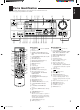
AUDIO/VIDEO CONTROL RECEIVER AUDIO/VIDEO-RECEIVER MIT STEUEREINHEIT AMPLI/TUNER DE COMMANDE AUDIO/VIDEO GEINTEGREERDE AUDIO/VIDEO-VERSTERKER RECEPTOR DE CONTROL DE AUDIO/VÍDEO RICEVITORE DI CONTROLLO AUDIO/VIDEO RX-888RBK TV/CATV/DBS VCR 1 DVD DVD MUILTI CD TAPE/MD TV/DBS VIDEO PHONO FM/AM VCR 1 VCR 2 ANALOG/DIGITAL SLEEP SURROUND CNTR TONE 1 ON/OFF CNTR 2 3 MENU TEST SURROUND REAR-L MODE 4 DISC EFFECT 5 6 ENTER REAR-R 8 7/P SOUND SEA MODE 9 SUBWOOFER 0 10 +10 RETURN
Warnings, Cautions and Others/Warnung, Achtung und sonstige Hinweise/ Mises en garde, précautions et indications diverses/Waarschuwingen, voorzorgen en andere mededelingen/Avisos, precauciones y otras notas/ Avvertenze e precauzioni da osservare IMPORTANT for the U.K. DO NOT cut off the mains plug from this equipment.
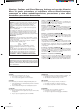
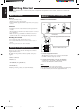
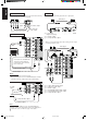
Spacing 15 cm or more Abstand von 15 cm oder mehr Dégagement de 15 cm ou plus Minstens 15 cm tussenruimte Espacio de 15 cm o más 15 cm di distanza o più Front Vorderseite Avant Voorkant Frente Davanti RX-888RBK Wall or obstructions Wand oder Hindernisse Mur, ou obstruction Wand of meubilair Pared u obstrucciones Parete o ostacol Stand height 15 cm or more Standhöhe 15 cm oder mehr Hauteur du socle: 15 cm ou plus Standard op minstens 15 cm van de vloer Allura del soporte 15 cm o más Altezza del tavolino
English Table of Contents Parts Identification ...................................... 2 Getting Started ........................................... 3 Before Installation ...................................................................... 3 Checking the Supplied Accessories ........................................... 3 Connecting the FM and AM (MW/LW) Antennas ..................... 3 Connecting the Speakers ............................................................ 4 Connecting Audio/Video Components .
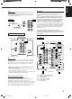
English Parts Identification Become familiar with the buttons and controls on the receiver before use. Refer to the pages in parentheses for details.
English Getting Started This section explains how to connect audio/video components and speakers to the receiver, and how to connect the power supply. Before Installation General • Be sure your hands are dry. • Turn the power off to all components. • Read the manuals supplied with the components you are going to connect.
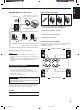
Snap the tabs on the loop into the slots of the base to assemble the AM (MW/LW) loop. ANTENNA FM 75 COAXIAL Basic connecting procedure AM (MW/LW) Loop Antenna AM EXT 4 3 2 1 1 1 1 RIG AM LOOP English AM (MW/LW) Antenna Connections RIG HT HT RIG HT 1 Cut, twist and remove the insulation at the end of each speaker signal cable (not supplied). 2 Turn the knob counterclockwise. 1 2 3 3 Insert the speaker signal cable. 4 Turn the knob clockwise.
English About the speaker impedance Connecting the subwoofer speaker The required speaker impedance of the front speakers does differ depending on whether both the FRONT SPEAKERS 1 and FRONT SPEAKERS 2 terminals are used or only one of them is used. You can enhance the bass by connecting a subwoofer. Connect the input jack of a powered subwoofer to the SUBWOOFER OUT jack on the rear panel, using a cable with RCA pin plugs (not supplied).
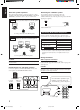
IMPORTANT: Any turntables incorporating a small-output cartridge such as an MC (moving-coil type) must be connected to this receiver through a commercial head amplifier or step-up transformer. Direct connection may result in insufficient volume. This receiver is equipped with both the composite video and S-video input/output terminals for connecting video components. You do not have to connect both the composite video and S-video terminals.
English DVD player Video camera The VIDEO jacks on the front panel is convenient when connecting and disconnecting the equipment frequently.
English Connecting the Power Cord Digital connections This receiver is equipped with three DIGITAL IN terminals — one digital coaxial terminal and two digital optical terminals. You can connect any component to any one of the digital terminals using the digital coaxial cable (not supplied) or digital optical cable (not supplied).
English Basic Operations The following operations are commonly used when you play any sound source. From the remote control: Press one of the source selecting buttons. IMPORTANT: When using the remote control, check to see if its remote control mode selector is set to the correct position: To operate an audio system, TV, and VCR, set it to “AUDIO/TV/VCR.” To operate a CATV converter and DBS tuner, set it to “CATV/DBS.
• The DIGITAL SOURCE FORMAT lamps on the front panel indicate what type of the digital signal comes into the receiver. DIGITAL SOURCE FORMAT MPEG DTS DOLBY DIGITAL LINEAR PCM MPEG: Lights up when MPEG Multichannel signals (see page 24) come in. DTS: Lights up when DTS Digital Surround signals (see page 24) come in. DOLBY DIGITAL: Lights up when Dolby Digital signals (see page 24) come in. LINEAR PCM: Lights up when Linear PCM signals come in.
English Listening only with headphones 1. Connect a pair of headphones to the PHONES jack on the front panel. 2. Press SPEAKERS 1 and/or 2 so that no lamps on the buttons are turned on. CAUTION: Be sure to turn down the volume before connecting or putting on headphones, as high volume can damage both the headphones and your hearing. Muting the Sound Attenuating the Input Signal When the input level of the playing source is too high, the sounds will be distorted.
Some of the following settings are required after connecting and positioning your speakers in your listening room, while others will make operations easier. IMPORTANT: Changing the Source Name When using the remote control, check to see if its remote control mode selector is set to the correct position: To operate this receiver, set it to “AUDIO/TV/ VCR” (except when selecting the DBS tuner as the source).
English Digital Input (DIGITAL IN) Terminal Setting 2. Press INPUT ANALOG/DIGITAL to change the input mode. When you use the digital input terminals, you have to register what components are connected to which terminals (DIGITAL IN 1/2/3). Before you start, remember.... • There is a time limit in doing the following steps. If the setting is canceled before you finish, start from step 1 again. On the front panel ONLY: 1. Press SETTING repeatedly until “DIGITAL IN” appears on the display.
Center Delay Time Setting Before you start, remember.... • There is a time limit in doing the following steps. If the setting is canceled before you finish, start from step 1 again. Register the delay time of the sound from the center speaker, comparing that of the sound from the front speakers. If the distance from your listening point to the center speaker is equal to that to the front speakers, select 0 msec. As the distance to the center speaker becomes shorter, increase the delay time.
English MULTI JOG Crossover Frequency Setting Small speaker cannot reproduce the bass sound very well. So, if you have used a small speaker any for the front, center, or rear channels, this receiver automatically reallocates the bass elements, originally assigned to the channel for which you have connected the small speaker, to another channel (for which you have connected the large speaker).
JVC’s One Touch Operation function is used to assign and store different sound settings for each different playing source. By using this function, you do not have to change the settings every time you change the source. The stored settings for the newly selected source are automatically recalled.
English Receiving Radio Broadcasts You can browse through all the stations or use the preset function to go immediately to a particular station. IMPORTANT: Using Preset Tuning When using the remote control, check to see if its remote control mode selector is set to the correct position: To operate this receiver, set it to “AUDIO/TV/ VCR” (except when selecting the DBS tuner as the source). AUDIO/ TV/VCR CATV/DBS Once a station is assigned to a channel number, the station can be quickly tuned.
Note: When using the FM MODE/MUTING button on the remote control, be sure that the 10 keys are activated for tuner, not for the CD and others. (See page 45.) On the front panel: SOURCE SELECTOR 1. Turn SOURCE SELECTOR to select the band (FM or AM — MW/LW). Assigning Names to Preset Stations The last received station of the selected band is tuned in. TUNER PRESET You can assign a name of up to four characters to each preset station.
English Using the RDS (Radio Data System) to Receive FM Stations RDS allows FM stations to send an additional signal along with their regular program signals. For example, the stations send their station names, as well as information about what type of program they broadcast, such as sports or music, etc. When tuned to an FM station which provides the RDS service, the RDS indicator lights up on the display. You can also show the RDS information on the TV screen.
MULTI JOG PTY codes NONE The display gives you the PTY codes described to the right. 3. Press PTY SEARCH again, while the PTY code selected in the previous step is still on the display. PTY SEARCH To continue searching after the first stop Press PTY SEARCH again while the indications on the display are flashing. If no program is found, “NOTFOUND” appears on the display. From the remote control: “PTY SELECT” flashes on the display.
English Switching to a Broadcast Program of Your Choice Temporarily Another convenient RDS service is called “EON (Enhanced Other Network).” The EON indicator lights up while receiving a station with the EON code. This allows the receiver to switch temporarily to a broadcast program of your choice (NEWS, TA, and/or INFO) from a different station except in the following cases: • When you are listening to non-RDS stations (all AM — MW/LW and some FM stations).
English Using the SEA Modes The SEA (Sound Effect Amplifier) modes give you control of the way your music sounds. IMPORTANT: When using the remote control, check to see if its remote control mode selector is set to the correct position: To operate this receiver, set it to “AUDIO/TV/ VCR” (except when selecting the DBS tuner as the source). Creating Your Own SEA Mode AUDIO/ TV/VCR You can adjust and store your own SEA adjustment into memory (SEA USERMODE). CATV/DBS Before you start, remember...
English Using the DSP Modes The built-in Surround Processor provides three types of the DSP (Digital Signal Processor) mode — 3D-PHONIC mode, DAP (Digital Acoustic Processor) mode and Surround mode. 3D-PHONIC modes DAP modes The 3D-PHONIC mode gives you such a nearly surround effect as it is reproduced through the Dolby Surround decoder, which is widely used to reproduce sounds with a feeling of movement like those experienced in movie theaters.
English Surround modes With this receiver, you can use four types of the Surround mode. Following modes cannot be used when only the front speakers are connected to this receiver (without the rear speakers or center speaker). Dolby Surround (Dolby Digital and Dolby Pro Logic)* Used to watch the soundtracks of software encoded with Dolby ) or with Dolby Surround Digital (bearing the mark DOLBY SURROUND ).
English Available DSP Modes According to the Speaker Arrangement Available DSP modes will vary depending on how many speakers are used with this receiver. Make sure that you have set the speaker information correctly (see page 14).
When using the remote control, check to see if its remote control mode selector is set to the correct position: To operate this receiver, set it to “AUDIO/TV/ VCR” (except when selecting the DBS tuner as the source). CATV/DBS DSP EFFECT 1 Before you start, remember... • Make sure that you have set the speaker information correctly (see page 14). • There is a time limit in doing the following steps. If the setting is canceled before you finish, start from step 1 again.
English 3. Adjust the effect level. 1) Press BALANCE/SURROUND ADJUST repeatedly until “DSP EFFECT” appears on the display. The display changes to show the current setting. 2) Turn MULTI JOG to select the effect level. • As you turn it, the effect level changes as follows: DSP EFFECT 1 DSP EFFECT 2 DSP EFFECT 5 BALANCE/SURROUND ADJUST Adjusting the Surround Modes Once you have adjusted the Surround modes, the adjustment is memorized for each Surround mode.
• You can adjust the speaker output levels without outputting the test tone. • No test tone comes out of the center speaker when “CENTER SPK” is set to “NONE” (see page 14). • No test tone comes out of the rear speakers when “REAR SPK” is set to “NONE” (see page 14). • If the TV is turned on and the proper video input is selected on the TV, the test tone screen will appear on the TV. • The signal indicators also light on the display while the test tone comes out of the speakers.
English JVC Theater Surround adjustments 4. Adjust the speaker output levels. Before you start, remember... • Make sure that you have set the speaker information correctly (see page 14). • There is a time limit in doing the following steps. If the setting is canceled before you finish, start from step 1 again. • You cannot adjust the rear speaker output levels when you have set “REAR SPK” to “NONE.” See page 14.
DSP MODE 1. Press DSP MODE repeatedly until “THEATER” or “DIG THEATER” appears on the display. 1) Press BALANCE/SURROUND ADJUST repeatedly until one of the indications appears on the display. “CENTER LEVEL”: To adjust the center speaker level. “REAR L LEVEL”: To adjust the left rear speaker level. “REAR R LEVEL”: To adjust the right rear speaker level. 2) Turn MULTI JOG to adjust the selected speaker output level (from –10 dB to +10 dB). 3) Repeat 1) and 2) to adjust the other speaker output levels.
English For the other DSP modes ––––––––––––––– MEMO ––––––––––––––– On the front panel: 1. Press DSP MODE repeatedly until the mode you want appears on the display. DSP MODE Use this column to write down your DSP mode adjustments for your future reference. • Each time you press the button, the DSP modes change. (See page 25 for more details.) 2. Select and play a sound source.
English Using the DVD MULTI Playback Mode This receiver provides the DVD MULTI playback mode for reproducing the analog discrete output mode of the DVD player. Before playing back a DVD, refer also to the manual supplied with the DVD player. 4. Adjust the center tone. IMPORTANT: When using the remote control, check to see if its remote control mode selector is set to the correct position: To operate this receiver, set it to “AUDIO/TV/ VCR” (except when selecting the DBS tuner as the source).
English From the remote control: ––––––––––––––– MEMO ––––––––––––––– DVD MUILTI 1. Press DVD MULTI so that “DVD MULTI” appears on the display. Use this column to write down your DVD MULTI playback mode adjustments for your future reference. Note: When you select “DVD MULTI” as the source to play, the DSP mode is canceled temporarily, and the SURROUND ON/OFF and SURROUND MODE buttons do not work. 2. Select the analog discrete output mode on the DVD player, and start playing a DVD.
You can use the Menus on the TV screen to control the receiver. To use this function, you need to connect the TV to the MONITOR OUT jack on the rear panel (see page 7), and set the TV’s input mode to the proper position to which the receiver is connected. • When the TV’s input mode is incorrect; for example, a different video input or TV tuner mode is selected, you cannot show the Menus on the TV screen.
English Listening at Low Volume (Loudness) (Also see page 11) 1. Press MENU. The MAIN MENU appears on the TV. • Pressing one of the % / fi / @ / # buttons also displays the MAIN MENU. 2. Press % / fi to move to “SOUND CONTROL,” then press @ / #. The SOUND CONTROL menu appears. 3. Press % / fi to move to “LOUDNESS.” SOUND CONTROL SURROUND LEVEL SEA 4. Press @ / # to turn the loudness “ON” or “OFF.” BAL.:R-21 LOUDNESS : OFF INPUT ATT : NORMAL SUBWFR LEVEL: 0dB NEXT PAGE :OPERATE 5.
Notes: * Not displayed when “REAR SPK” is set to “NONE” (see page 14). ** Not displayed when “CENTER SPK” is set to “NONE” (see page 14). 7. When you finish, press EXIT repeatedly until the menu disappears from the TV. Activating the DVD MULTI Playback Mode (Also see page 32) 1. Press MENU. The MAIN MENU appears on the TV. • Pressing one of the % / fi / @ / # buttons also displays the MAIN MENU. 2. Press % / fi to move to “SOURCE.” 4. Press % / fi to move to “SOUND CONTROL,” then press @ / #.
English 4. Press % / fi to move to “SEA ADJUST.” “LFE ATT.”: SEA ADJUST SEA USERMODE “COMP.”: The SEA ADJUST menu appears. 100 5. Press % / fi / @ / # to adjust the SEA mode as you want. 1k 10kHz “DIGITAL 1/2/3”: SET:MEMORY “FL DISP.”: @ / # : Select the frequency ranges. % / fi : Adjust the frequency levels. Set the low frequency effect attenuator level (see page 15). Set the dynamic range compression (see page 15). Set the digital input terminal (see page 13).
1. Press MENU. The MAIN MENU appears on the TV. • Pressing one of the % / fi / @ / # buttons also displays the MAIN MENU. 2. Press % / fi to move to “TUNER CONTROL,” then press @ / #. The TUNER CONTROL menu appears. 3. Tune into a station on the TUNER CONTROL menu, referring to “Operating the Tuner” on the previous page. 4. Press % / fi to move to “PRESET MEMORY,” then press @ / #. PRESET MEMORY FM 87.50MHz AUTO PRESET CH : CH 1 PRESET NAME: WABC The PRESET MEMORY menu appears.
English COMPU LINK Remote Control System The COMPU LINK remote control system allows you to operate JVC audio components through the remote sensor on the receiver. To use this remote control system, you need to connect JVC audio components through the COMPU LINK-3 (SYNCHRO) jacks (see below) in addition to the connections using cables with RCA pin plugs (see pages 5 and 6). • Make sure that the AC power cords of these components are unplugged before connection.
The TEXT COMPU LINK remote control system has been newly developed to deal with the disc information recorded in the CD Text* and MDs. Using these information in the discs, you can operate the CD player or MD recorder equipped with the TEXT COMPU LINK remote control system through the receiver. CONNECTIONS: FUNCTIONS: To use this remote control system, you need to connect the CD player and/or MD recorder you want to operate, following the procedures below. 1.
English OPERATIONS To use this remote control system, you need to connect the TV to the MONITOR OUT jack on the rear panel (see page 7), and set the TV’s input mode to the proper position to which the receiver is connected. Make sure you have connected the CD player or MD recorder equipped with the TEXT COMPU LINK remote control system. If not, you cannot use the following functions.
Search for a disc by its performer: 1. Press TEXT DISPLAY while “CD” is selected as the source. The Disc Information screen appears on the TV. 2. Press % / fi to move to “SEARCH,” then press SET. The DISC SEARCH screen appears . 3. Press % / fi to move to “PERFORMER”, then press SET. Search for a disc by its disc title: 1. Press TEXT DISPLAY while “CD” is selected as the source. The Disc Information screen appears on the TV. 2. Press % / fi to move to “SEARCH,” then press SET.
English Search for a disc by its genre: 1. Press TEXT DISPLAY while “CD” is selected as the source. The Disc Information screen appears on the TV. 2. Press % / fi to move to “SEARCH,” then press SET. The DISC SEARCH screen appears. 3. Press % / fi to move to “GENRE”, then press SET. The GENRE SEARCH screen appears. Entering the Disc Information For the CD Player with the disc memory function: You can use the disc memory function through this receiver.
To insert a space, press % / fi to / @ / # to move , then press SET. To correct an incorrect character: 1) Press % / fi / @ / # to move to + or =, then press SET until the incorrect character is selected. to , then press SET 2) Press % / fi / @ / # to move to erase the character. 3) Press % / fi / @ / # to move in front of the correct character, then press SET to enter a correct character. 5. Press % / fi / @ / # to to “DISC 1: move MICHAEL (in this example),” then press SET. 1.
English Operating JVC’s Audio/Video Components You can operate JVC’s audio and video components with this receiver’s remote control, since control signals for JVC components are preset in the remote control. IMPORTANT: To operate JVC’s audio components using this remote control: • You need to connect JVC audio components through the COMPU LINK-3 (SYNCHRO) jacks (see page 39) in addition to the connections using cables with RCA pin plugs (see pages 5 and 6).
After pressing PHONO (with the remote control mode selector set to “AUDIO/TV/VCR”), you can perform the following operations on a turntable: PLAY: STOP: Starts playing. Stops operations. Cassette deck After pressing TAPE/MD or TAPE CONTROL (with the remote control mode selector set to “AUDIO/TV/VCR”), you can perform the following operations on a cassette deck: PLAY: 1: ¡: STOP: PAUSE: ¶ REC: Starts playing. Fast winds the tape from right to left. Fast winds the tape from left to right. Stops operations.
English Operating Other Manufacturers’ Video Equipment This remote control supplied with the receiver can transmit control signals for other manufacturers’ VCRs, TVs, CATV converters and DBS tuners. By changing the transmittable signals from preset ones to the other manufacturers’, you can operate the other manufacturer’s components using this remote control. When operating the other manufacturers’ components, refer also to the manuals supplied with them.
To change the transmittable signals for operating another manufacturer’s VCR 1. Set the remote control mode to “CATV/DBS.” 1. Set the remote control mode to “AUDIO/TV/ VCR.” 2. Press and hold TV/CATV/DBS . 3. Press TV/DBS. 4. Enter manufacturer’s code (three digits) using buttons 1 – 9, and 0. See the list on pages 51 and 52 to find the code. Examples: For a JVC product, press 5, 1, then 5. For a Philips product, press 2, 0, then 0. 5. Release TV/CATV/DBS .
English Manufacturers’ codes for TV Acura Admiral Adyson AGB Akai Akura Alba Allorgan Amplivision Amstrad Anitech Arcam ASA Asberg Asuka Atlantic Audiosonic Autovox Baird Bang & Olufsen Barco Basic Line Baur Beko Beon Binatone Blaupunkt Blue Sky Blue Star Bondstec Boots BPL Brandt Brionvega Britannia Bruns BSR BTC Bush Carrefour Cascade Cathay Centurion Century CGE Cimline Clarivox Clatronic Clayton Condor Contec Continental Edison Crosley Crown Crystal CS Electrinics CTC Cybertron Daewoo Dainichi Dansai D
Magnadyne Magnafon Manesth Marantz Marelli Mark Matsui McMichael Mediator Memorex Memphis Metz Minerva Minoka Mitsubishi Mivar Motion MTC Multitech Neckermann NEI Nesco Nikkai Nobliko Nokia Nordmende Oceanic Onwa Orion Osaki Oso Osume Otake Otto Versand Palladilum Panama Panasonic Pathe Cinema Pathe Marconi Pausa Perdio Phase Philco Philips Phoenix Phonola Pioneer Prandoni Prince Profex Proline Protech Pye Quelle Questa R-Line Radiola Radiomarelli Rank Arena RBM Rediffusion Revox 349, 361 009, 037, 068, 10
English Vestel Videosat Videotechnic Vision Voxson Waltham Watson Watt Radio Wega White Westinghouse Yoko Zanussi 037 247 217 320 087, 163 217 037, 320 102 036, 087 037, 216, 320 037, 217, 264, 431 206 Manufacturers’ codes for DBS tuner Akai Alba Aldes Amstrad Ankaro Anttron Armstrong AST Astra Astro Avalon Axis BT Beko Best Blaupunkt Boca Brain Wave Bush Cambridge Channel Master CNT Commlink Connexions Conrad Crown Cyrus DDC DNT Echostar Emanon Ferguson Fidelity Finlux Freecom Fuba G-Sat Galaxis Gooding
Brigminghan Cable Communications British Telecom 003, 105 Decsat 423 Filmnet 443 France Telecom 451 Jerrold 003, 276 MNet 443 PVP Stereo Visual Matrix 003 Salora 382 Scientific Atlanta 008, 277 Tele+1 443 United Cable 003 Westminster 105 Zenith 000 276 Manufacturers’ codes for VCR Aiwa Akai Akiba Akura Alba Ambassador Amstrad Anitech ASA Asuka Baird Basic Line Blaupunkt Brandt Brandt Electronic Brionvega Bush Catron CGE Cimline Clatronic Combitech Condor Crown Cyrus Daewoo Dansai De Graaf Decca Denon Dual
English Samsung Sansui Sanyo Saville SBR Schaub Lorenz Schneider SEG SEI Seleco Sentra Sharp Shintom Shorai Siemens Silva Singer Sinudyne Solavox Sonolor Sontec Sony Sunkai Sunstar Suntronic Tashiko Tatung Tec Technics Teleavia Telefunken Tenosal Tensai Thomson Thorn Toshiba Towada Triumph Uher Ultravox Universum 240, 432 041, 067, 271 046, 104 352 081 000, 005, 041, 104, 344 000, 072, 081 240, 322 004, 081 041 020 048 072, 104 004 003, 006, 016, 037, 054, 081, 104, 195 037 045 004, 081 020 046 037 011, 0
Use this chart to help you solve daily operational problems. If there is any problem you cannot solve, contact your JVC service center. PROBLEM POSSIBLE CAUSE SOLUTION The display does not light up. The power cord is not plugged in. Plug the power cord into an AC outlet. No sound from speakers. Speaker signal cables are not connected. Check speaker wiring and reconnect if necessary. The SPEAKERS 1 and 2 buttons are not set correctly. Press SPEAKERS 1 and 2 correctly.
English Specifications Amplifier Output Power At Stereo operation: Front channels: 100 watts per channel, min. RMS, driven into 4 ohms, 1 kHz with no more than 0.8% total harmonic distortion. (IEC268-3/DIN) At Surround operation: Total Harmonic Distortion (8 ohms): Audio Audio Input Sensitivity/Impedance (1 kHz): Audio Input (DIGITAL IN)* : Front channels: 70 watts per channel, min. RMS, driven into 4 ohms at 1 kHz with no more than 0.8% total harmonic distortion. Center channel: 70 watts, min.
English FM tuner (IHF) Tuning Range: 87.50 MHz to 108.00 MHz Usable Sensitivity: Monaural: 12.8 dBf (1.2 µV/75 ohms) 50 dB Quieting Sensitivity: Monaural: Stereo: 21.3 dBf (3.2 µV/75 ohms) 41.3 dBf (31.5 µV/75 ohms) Signal-to-Noise Ratio (IHF-A weighted): Monaural: Stereo: 78 dB at 85 dBf 73 dB at 85 dBf Total Harmonic Distortion: Monaural: Stereo: 0.4% at 1 kHz 0.
VICTOR COMPANY OF JAPAN, LIMITED V EN, GE, FR, NL, SP, IT RX-888R[E]COVER/f J 2 99.4.