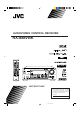
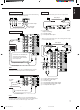
AUDIO/VIDEO CONTROL RECEIVER RX-888VBK ON STANDBY TV/CATV/DBS VCR 1 POWER POWER DVD DVD MUILTI CD TAPE/MD TV/DBS VIDEO PHONO FM/AM VCR 1 VCR 2 ANALOG/DIGITAL SLEEP SURROUND CNTR TONE ON/OFF 1 SURROUND TEST MODE 4 CNTR 2 3 MENU REAR-L 5 6 ENTER DISC EFFECT SOUND SEA MODE REAR-R 8 7/P 9 SUBWOOFER 0 10 +10 RETURN FM MODE/MUTING 100+ AUDIO/ TV/VCR MASTER VOLUME MENU CATV/DBS RX-888V AUDIO/VIDEO CONTROL RECEIVER D I G I T A L SET – TEXT DISPLAY EXIT STANDBY
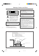
Warnings, Cautions and Others CAUTION Caution –– POWER switch! Disconnect the mains plug to shut the power off completely. The POWER switch in any position does not disconnect the mains line. The power can be remote controlled. RISK OF ELECTRIC SHOCK DO NOT OPEN CAUTION: TO REDUCE THE RISK OF ELECTRIC SHOCK. DO NOT REMOVE COVER (OR BACK) NO USER SERVICEABLE PARTS INSIDE. REFER SERVICING TO QUALIFIED SERVICE PERSONNEL.
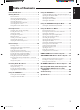
Parts Identification ...................................... 2 Using the DSP Modes ................................ 20 Getting Started ........................................... 3 Available DSP Modes According to the Speaker Arrangement .. 22 Adjusting the 3D-PHONIC Modes .......................................... 23 Adjusting the DAP Modes ....................................................... 23 Adjusting the Surround Modes ................................................ 24 Activating the DSP Modes .
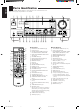
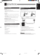
English Parts Identification Become familiar with the buttons and controls on the receiver before use. Refer to the pages in parentheses for details.
English Getting Started This section explains how to connect audio/video components and speakers to the receiver, and how to connect the power supply. Before Installation General • Be sure your hands are dry. • Turn the power off to all components. • Read the manuals supplied with the components you are going to connect.
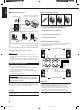
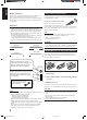
English Basic connecting procedure AM Antenna Connections Snap the tabs on the loop into the slots of the base to assemble the AM loop. ANTENNA FM 75 COAXIAL 1 AM Loop Antenna AM EXT 1 1 RIG AM LOOP 4 3 2 1 RIG HT RIG HT HT 1 Cut, twist and remove the insulation at the end of each speaker signal cable (not supplied). 2 Turn the knob counterclockwise. 1 2 3 3 Insert the speaker signal cable. 4 Turn the knob clockwise.
Analog connections Connect rear speakers to the REAR SPEAKERS terminals and a center speaker to the CENTER SPEAKER terminals. Audio component connections Use the cables with RCA pin plugs (not supplied). Connect the white plug to the audio left jack, and the red plug to the audio right jack.
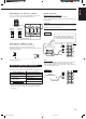
English IMPORTANT: Cassette deck or MD recorder Cassette deck To audio input To audio output RIGHT LEFT AUDIO PHONO CD OUT (REC) TAPE /MD This receiver is equipped with both the composite video and S-video input/output terminals for connecting video components. You do not have to connect both the composite video and S-video terminals.
The VIDEO jacks on the front panel is convenient when connecting and disconnecting the equipment frequently.
English Connecting the Power Cord Digital connections This receiver is equipped with three DIGITAL IN terminals — one digital coaxial terminal and two digital optical terminals. You can connect any component to any one of the digital terminals using the digital coaxial cable (not supplied) or digital optical cable (not supplied).
English Basic Operations The following operations are commonly used when you play any sound source. From the remote control: Press one of the source selecting buttons. IMPORTANT: When using the remote control, check to see if its remote control mode selector is set to the correct position: To operate an audio system, TV, and VCR, set it to “AUDIO/TV/VCR.” To operate a CATV converter and DBS tuner, set it to “CATV/DBS.
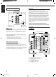
English When playing a digital source through a digital terminal • The DIGITAL SOURCE FORMAT lamps on the front panel indicate what type of the digital signal comes into the receiver. DIGITAL SOURCE FORMAT DTS DOLBY DIGITAL LINEAR PCM DTS: Lights up when DTS Digital Surround signals (see page 21) come in. DOLBY DIGITAL: Lights up when Dolby Digital signals (see page 21) come in. LINEAR PCM: Lights up when Linear PCM signals come in.
CAUTION: Be sure to turn down the volume before connecting or putting on headphones, as high volume can damage both the headphones and your hearing. Muting the Sound English Listening only with headphones 1. Connect a pair of headphones to the PHONES jack on the front panel. 2. Press SPEAKERS 1 and/or 2 so that no lamps on the buttons are turned on. Attenuating the Input Signal When the input level of the playing source is too high, the sounds will be distorted.
English Basic Settings Some of the following settings are required after connecting and positioning your speakers in your listening room, while others will make operations easier. IMPORTANT: Changing the Source Name When using the remote control, check to see if its remote control mode selector is set to the correct position: To operate this receiver, set it to “AUDIO/TV/ VCR” (except when selecting the DBS tuner as the source).
2. Press INPUT ANALOG/DIGITAL to change the input mode. When you use the digital input terminals, you have to register what components are connected to which terminals (DIGITAL IN 1/2/3). Before you start, remember.... • There is a time limit in doing the following steps. If the setting is canceled before you finish, start from step 1 again. On the front panel ONLY: 1. Press SETTING repeatedly until “DIGITAL IN” appears on the display. SETTING DIGITAL 2 terminal setting From the remote control: 1.
English Setting the Speakers for the DSP Modes Center Delay Time Setting Before you start, remember.... • There is a time limit in doing the following steps. If the setting is canceled before you finish, start from step 1 again. Register the delay time of the sound from the center speaker, comparing that of the sound from the front speakers. If the distance from your listening point to the center speaker is equal to that to the front speakers, select 0 msec.
English MULTI JOG Crossover Frequency Setting Small speaker cannot reproduce the bass sound very well. So, if you have used a small speaker any for the front, center, or rear channels, this receiver automatically reallocates the bass elements, originally assigned to the channel for which you have connected the small speaker, to another channel (for which you have connected the large speaker).
English Storing the Basic Settings and Adjustments — One Touch Operation JVC’s One Touch Operation function is used to assign and store different sound settings for each different playing source. By using this function, you do not have to change the settings every time you change the source. The stored settings for the newly selected source are automatically recalled.
English Receiving Radio Broadcasts You can browse through all the stations or use the preset function to go immediately to a particular station. IMPORTANT: Using Preset Tuning When using the remote control, check to see if its remote control mode selector is set to the correct position: To operate this receiver, set it to “AUDIO/TV/ VCR” (except when selecting the DBS tuner as the source). AUDIO/ TV/VCR Once a station is assigned to a channel number, the station can be quickly tuned.
English To tune in a preset station Note: When using the FM MODE/MUTING button on the remote control, be sure that the 10 keys are activated for tuner, not for the CD and others. (See page 44.) On the front panel: SOURCE SELECTOR 1. Turn SOURCE SELECTOR to select the band (FM or AM). The last received station of the selected band is tuned in. Assigning Names to Preset Stations TUNER PRESET 2. Press TUNER PRESET. You can assign a name of up to four characters to each preset station.
English Using the SEA Modes The SEA (Sound Effect Amplifier) modes give you control of the way your music sounds. IMPORTANT: When using the remote control, check to see if its remote control mode selector is set to the correct position: To operate this receiver, set it to “AUDIO/TV/ VCR” (except when selecting the DBS tuner as the source). Creating Your Own SEA Mode AUDIO/ TV/VCR You can adjust and store your own SEA adjustment into memory (SEA USERMODE). CATV/DBS Before you start, remember...
English Using the DSP Modes The built-in Surround Processor provides three types of the DSP (Digital Signal Processor) mode — 3D-PHONIC mode, DAP (Digital Acoustic Processor) mode and Surround mode. 3D-PHONIC modes DAP modes The 3D-PHONIC mode gives you such a nearly surround effect as it is reproduced through the Dolby Surround decoder, which is widely used to reproduce sounds with a feeling of movement like those experienced in movie theaters.
Notes: With this receiver, you can use three types of the Surround mode. Following modes cannot be used when only the front speakers are connected to this receiver (without the rear speakers or center speaker). • The DSP modes have no effect on monaural sources. • The DSP modes cannot be used for recording an analog source. • When you select “DVD MULTI” as the source to play, you cannot select or adjust the DSP modes.
English Available DSP Modes According to the Speaker Arrangement Available DSP modes will vary depending on how many speakers are used with this receiver. Make sure that you have set the speaker information correctly (see page 14).
When using the remote control, check to see if its remote control mode selector is set to the correct position: To operate this receiver, set it to “AUDIO/TV/ VCR” (except when selecting the DBS tuner as the source). CATV/DBS DSP EFFECT 1 Before you start, remember... • Make sure that you have set the speaker information correctly (see page 14). • There is a time limit in doing the following steps. If the setting is canceled before you finish, start from step 1 again.
English 3. Adjust the effect level. 1) Press BALANCE/SURROUND ADJUST repeatedly until “DSP EFFECT” appears on the display. The display changes to show the current setting. 2) Turn MULTI JOG to select the effect level. • As you turn it, the effect level changes as follows: DSP EFFECT 1 DSP EFFECT 2 DSP EFFECT 5 BALANCE/SURROUND ADJUST Adjusting the Surround Modes Once you have adjusted the Surround modes, the adjustment is memorized for each Surround mode.
• You can adjust the speaker output levels without outputting the test tone. • No test tone comes out of the center speaker when “CENTER SPK” is set to “NONE” (see page 14). • No test tone comes out of the rear speakers when “REAR SPK” is set to “NONE” (see page 14). • If the TV is turned on and the proper video input is selected on the TV, the test tone screen will appear on the TV. • The signal indicators also light on the display while the test tone comes out of the speakers.
English JVC Theater Surround adjustments 4. Adjust the speaker output levels. Before you start, remember... • Make sure that you have set the speaker information correctly (see page 14). • There is a time limit in doing the following steps. If the setting is canceled before you finish, start from step 1 again. • You cannot adjust the rear speaker output levels when you have set “REAR SPK” to “NONE.” See page 14.
DSP MODE 1. Press DSP MODE repeatedly until “THEATER” or “DIG THEATER” appears on the display. 1) Press BALANCE/SURROUND ADJUST repeatedly until one of the indications appears on the display. “CENTER LEVEL”: To adjust the center speaker level. “REAR L LEVEL”: To adjust the left rear speaker level. “REAR R LEVEL”: To adjust the right rear speaker level. 2) Turn MULTI JOG to adjust the selected speaker output level (from –10 dB to +10 dB). 3) Repeat 1) and 2) to adjust the other speaker output levels.
English For the other DSP modes ––––––––––––––– MEMO ––––––––––––––– On the front panel: 1. Press DSP MODE repeatedly until the mode you want appears on the display. DSP MODE Use this column to write down your DSP mode adjustments for your future reference. • Each time you press the button, the DSP modes change. (See page 22 for more details.) 2. Select and play a sound source.
English Using the DVD MULTI Playback Mode This receiver provides the DVD MULTI playback mode for reproducing the analog discrete output mode of the DVD player. Before playing back a DVD, refer also to the manual supplied with the DVD player. 4. Adjust the center tone. IMPORTANT: When using the remote control, check to see if its remote control mode selector is set to the correct position: To operate this receiver, set it to “AUDIO/TV/ VCR” (except when selecting the DBS tuner as the source).
English From the remote control: ––––––––––––––– MEMO ––––––––––––––– DVD MUILTI 1. Press DVD MULTI so that “DVD MULTI” appears on the display. Use this column to write down your DVD MULTI playback mode adjustments for your future reference. Note: When you select “DVD MULTI” as the source to play, the DSP mode is canceled temporarily, and the SURROUND ON/OFF and SURROUND MODE buttons do not work. 2. Select the analog discrete output mode on the DVD player, and start playing a DVD.
You can use the Menus on the TV screen to control the receiver. To use this function, you need to connect the TV to the MONITOR OUT jack on the rear panel (see page 7), and set the TV’s input mode to the proper position to which the receiver is connected. • When the TV’s input mode is incorrect; for example, a different video input or TV tuner mode is selected, you cannot show the Menus on the TV screen.
English Listening at Low Volume (Loudness) (Also see page 11) 1. Press MENU. The MAIN MENU appears on the TV. • Pressing one of the % / fi / @ / # buttons also displays the MAIN MENU. 2. Press % / fi to move to “SOUND CONTROL,” then press @ / #. The SOUND CONTROL menu appears. 3. Press % / fi to move to “LOUDNESS.” 4. Press @ / # to turn the loudness “ON” or “OFF.” SOUND CONTROL SURROUND LEVEL SEA BAL.:R-21 LOUDNESS : OFF INPUT ATT : NORMAL SUBWFR LEVEL: 0dB NEXT PAGE :OPERATE 5.
6. Press % / fi to move to the item you want to set or adjust, then press @ / #. On this adjustment menu, you can do the following: “CENTER LEVEL”: Adjust the center speaker output level. “REAR L LEVEL”: Adjust the left rear speaker output level. “REAR R LEVEL”: Adjust the right rear speaker output level. “CENTER TONE”: Select the center tone level. 7. When you finish, press EXIT repeatedly until the menu disappears from the TV. Selecting Your Favorite SEA Mode (Also see page 19) 1. Press MENU.
English 4. Press % / fi to move to “SEA ADJUST.” “LFE ATT.”: SEA ADJUST SEA USERMODE “COMP.”: The SEA ADJUST menu appears. 100 5. Press % / fi / @ / # to adjust the SEA mode as you want. 1k 10kHz “DIGITAL 1/2/3”: SET:MEMORY “FL DISP.”: @ / # : Select the frequency ranges. % / fi : Adjust the frequency levels. Set the low frequency effect attenuator level (see page 15). Set the dynamic range compression (see page 15). Set the digital input terminal (see page 13).
1. Press MENU. The MAIN MENU appears on the TV. • Pressing one of the % / fi / @ / # buttons also displays the MAIN MENU. 2. Press % / fi to move to “TUNER CONTROL,” then press @ / #. The TUNER CONTROL menu appears. 3. Tune into a station on the TUNER CONTROL menu, referring to “Operating the Tuner” on the previous page. 4. Press % / fi to move to “PRESET MEMORY,” then press @ / #. PRESET MEMORY FM 87.5 MHz AUTO PRESET CH : CH 1 PRESET NAME: WABC 6.
English COMPU LINK Remote Control System The COMPU LINK remote control system allows you to operate JVC audio components through the remote sensor on the receiver. To use this remote control system, you need to connect JVC audio components through the COMPU LINK-3 (SYNCHRO) jacks (see below) in addition to the connections using cables with RCA pin plugs (see pages 5 and 6). • Make sure that the AC power cords of these components are unplugged before connection.
The TEXT COMPU LINK remote control system has been newly developed to deal with the disc information recorded in the CD Text* and MDs. Using these information in the discs, you can operate the CD player or MD recorder equipped with the TEXT COMPU LINK remote control system through the receiver. CONNECTIONS: FUNCTIONS: To use this remote control system, you need to connect the CD player and/or MD recorder you want to operate, following the procedures below. 1.
English OPERATIONS To use this remote control system, you need to connect the TV to the MONITOR OUT jack on the rear panel (see page 7), and set the TV’s input mode to the proper position to which the receiver is connected. Make sure you have connected the CD player or MD recorder equipped with the TEXT COMPU LINK remote control system. If not, you cannot use the following functions.
Search for a disc by its performer: 1. Press TEXT DISPLAY while “CD” is selected as the source. The Disc Information screen appears on the TV. 2. Press % / fi to move to “SEARCH,” then press SET. The DISC SEARCH screen appears . 3. Press % / fi to move to “PERFORMER”, then press SET. Search for a disc by its disc title: 1. Press TEXT DISPLAY while “CD” is selected as the source. The Disc Information screen appears on the TV. 2. Press % / fi to move to “SEARCH,” then press SET.
English Search for a disc by its genre: 1. Press TEXT DISPLAY while “CD” is selected as the source. The Disc Information screen appears on the TV. 2. Press % / fi to move to “SEARCH,” then press SET. The DISC SEARCH screen appears. 3. Press % / fi to move to “GENRE”, then press SET. The GENRE SEARCH screen appears. 4. Press % / fi to move to the genre you want to search, then press SET. To show the unseen genres, press % / fi until they appear.
To insert a space, press % / fi to / @ / # to move , then press SET. To correct an incorrect character: 1) Press % / fi / @ / # to move to + or =, then press SET until the incorrect character is selected. to , then press SET 2) Press % / fi / @ / # to move to erase the character. 3) Press % / fi / @ / # to move in front of the correct character, then press SET to enter a correct character. 5. Press % / fi / @ / # to to “DISC 1: move MICHAEL (in this example),” then press SET.
English AV COMPU LINK Remote Control System The AV COMPU LINK remote control system allows you to operate JVC video components (TV, VCR, and DVD player) through the receiver. To use this remote control system, you need to connect the video components you want to operate, follow the diagrams below and the procedure on the next page.
2. Connect your VCR 1, DVD player, TV, and this receiver as follows, using the cables with the monaural mini-plugs (not supplied). • See “CONNECTIONS 1” on the previous page. 3. Connect the audio input/output jacks on VCR 1, DVD player, TV, and this receiver using the cables with RCA pin plug • See pages 6 and 7. One-Touch DVD Play Simply by starting playback on the DVD player, you can enjoy the DVD playback without setting other switches manually.
English Operating JVC’s Audio/Video Components You can operate JVC’s audio and video components with this receiver’s remote control, since control signals for JVC components are preset in the remote control. IMPORTANT: To operate JVC’s audio components using this remote control: • You need to connect JVC audio components through the COMPU LINK-3 (SYNCHRO) jacks (see page 36) in addition to the connections using cables with RCA pin plugs (see pages 5 and 6).
After pressing PHONO (with the remote control mode selector set to “AUDIO/TV/VCR”), you can perform the following operations on a turntable: PLAY: STOP: Starts playing. Stops operations. Cassette deck After pressing TAPE/MD or TAPE CONTROL (with the remote control mode selector set to “AUDIO/TV/VCR”), you can perform the following operations on a cassette deck: PLAY: 1: ¡: STOP: PAUSE: ¶ REC: Starts playing. Fast winds the tape from right to left. Fast winds the tape from left to right. Stops operations.
English Operating Other Manufacturers’ Video Equipment This remote control supplied with the receiver can transmit control signals for other manufacturers’ VCRs, TVs, CATV converters and DBS tuners. By changing the transmittable signals from preset ones to the other manufacturers’, you can operate the other manufacturer’s components using this remote control. When operating the other manufacturers’ components, refer also to the manuals supplied with them.
To change the transmittable signals for operating another manufacturer’s VCR 1. Set the remote control mode to “CATV/DBS.” 1. Set the remote control mode to “AUDIO/TV/ VCR.” 2. Press and hold TV/CATV/DBS POWER. 3. Press TV/DBS. 4. Enter manufacturer’s code (three digits) using buttons 1–9, and 0. See the list on page 49 to find the code. Examples: For a JVC product, press 7, 7, then 5. For a Pioneer product, press 1, 4, then 4. 5. Release TV/CATV/DBS POWER.
English Manufacturers’ codes for TV Admiral Aiko Akai Alaron Ambassador Anam Anam National AOC Audiovox Baysonic Belcor Bell & Howell Bradford Brockwood Brocksonic Candle Carnivale Carver Celebrity Cineral Citizen Clairtone Concerto Contec Craig Crosley Crown Curtis Mathes CXC Daewoo Daytron Denon Dumont Electroband Emerson Envision Fisher Fujitsu Funai Futuretech GE Gibralter GoldStar Gradiente Grunpy Hallmark Harley Davidson Harvard Hitachi Infinity Inteq JBL JCB JVC Kaypani KEC Kenwood KTV 093 092 030
English Manufacturers’ codes for CATV converters Signature Simpson Sony Soundesign Squareview SSS Starlite Supreme Sylvania Symphonic Tandy Tatung Technics Technol Ace Techwood Teknika Telefunken TMK Toshiba Tosonic Totevision Vector Research Victor Vidikron Vidtech Wards Yamaha Zenith 016 186, 187 000 178, 179, 180, 186 171 019, 180 180 000 020, 030, 054, 096 171 093 055 051, 250 179 051, 056 016, 019, 039, 054, 056, 060, 092, 150, 179, 180, 186 056 056, 177, 178 060, 154, 156 185 039 030 053 054 019, 17
English Manufacturers’ codes for VCR Admiral Adventura Aiko Aiwa Akai American High Asha Audiovox Beaumark Bell & Howell Broksonic Calix Canon Capehart Carver CCE Cineral Citizen Colt Craig Curtis Mathes Cybernex Daewoo Daytron Denon Dynatech Electrohome Electrophonic Emerex Emerson Fisher Fuji Funai Garrard GE GoldStar Gradiente Harley Davidson Harman/Kardon Harwood Headquarter Hitachi HI-Q Jensen JVC KEC Kenwood KLH Kodak Lloyd’s Logik LXI Magnasonic 048 000 278 000, 037 041, 053, 106 035 240 037 240 10
072 000, 032, 033, 034, 035 042 000, 035, 043, 081 000 041 000, 041 035, 162 000, 035, 037 000 240 043, 045, 212 037, 240 240 045 038 045 240 000, 035, 042, 047, 048, 060, 072, 081, 149, 212, 240 White Westinghouse 278 XR-1000 000, 035, 072 Yamaha 038 Zenith 000, 033, 034, 039 English Singer Sony STS Sylvania Symphonic Tatung Teac Technics Teknika Thomas TMK Toshiba Totevision Unitech Vector Vector Research Video Concepts Videosonic Wards Manufacturers’ codes listed on page 48 to 51 are subject to change
English Troubleshooting Use this chart to help you solve daily operational problems. If there is any problem you cannot solve, contact your JVC service center. PROBLEM POSSIBLE CAUSE SOLUTION The display does not light up. The power cord is not plugged in. Plug the power cord into an AC outlet. No sound from speakers. Speaker signal cables are not connected. Check speaker wiring and reconnect if necessary. The SPEAKERS 1 and 2 buttons are not set correctly. Press SPEAKERS 1 and 2 correctly.
English Specifications Amplifier Output Power At Stereo operation: Front channels: 120 watts per channel, min. RMS, driven into 8 ohms, 20 Hz to 20 kHz with no more than 0.02% total harmonic distortion. 120 watts per channel, min. RMS, driven into 4 ohms, 20 Hz to 20 kHz with no more than 0.08% total harmonic distortion. At Surround operation: Audio Audio Input Sensitivity/Impedance (1 kHz): Audio Input (DIGITAL IN)* : Front channels: 100 watts per channel, min.
English FM tuner (IHF) Tuning Range: 87.5 MHz to 108.0 MHz Usable Sensitivity: Monaural: 12.8 dBf (1.2 µV/75 ohms) 50 dB Quieting Sensitivity: Monaural: Stereo: 21.3 dBf (3.2 µV/75 ohms) 41.3 dBf (31.5 µV/75 ohms) Signal-to-Noise Ratio (IHF-A weighted): Monaural: Stereo: 78 dB at 85 dBf 73 dB at 85 dBf Total Harmonic Distortion: Monaural: Stereo: 0.4% at 1 kHz 0.
QUALITY SERVICE HOW TO LOCATE YOUR JVC SERVICE CENTER TOLL FREE : 1-800-537-5722 http://www.jvcservice.com Dear customer: In order to receive the most satisfaction from your purchase, read the instruction booklet before operating the unit. In the event that repair is necessary, or for the address nearest your location, please refer to the factory service center list below or within the Continental United States, Call 1-800-537-5722 for your authorized servicer.
LIMITED WARRANTY AUDIO-2 JVC COMPANY OF AMERICA warrants this product and all parts thereof, except as set forth below ONLY TO THE ORIGINAL PURCHASER AT RETAIL to be FREE FROM DEFECTIVE MATERIAL AND WORKMANSHIP from the date of original retail purchase for the period as shown below. (“The Warranty Period.”) PARTS LABOR 2YR 2YR THIS LIMITED WARRANTY IS VALID ONLY IN THE FIFTY(50) UNITED STATES, THE DISTRICT OF COLUMBIA AND IN COMMONWEALTH OF PUERTO RICO.
VICTOR COMPANY OF JAPAN, LIMITED V EN RX-888V[J]COVER/3 J 2 99.6.