AUDIO / VIDEO CONTROL RECEIVER RX-D201S / RX-D202B INSTRUCTIONS For Customer Use: Enter below the Model No. and Serial No. which are located either on the rear, bottom or side of the cabinet. Retain this information for future reference. Model No. Serial No.
Warnings, Cautions, and Others Mises en garde, précautions et indications diverses CAUTION RISK OF ELECTRIC SHOCK DO NOT OPEN CAUTION: TO REDUCE THE RISK OF ELECTRIC SHOCK, DO NOT REMOVE COVER (OR BACK). NO USER SERVICEABLE PARTS INSIDE. REFER SERVICING TO QUALIFIED SERVICE PERSONNEL.
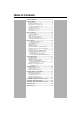
Table of Contents Parts identification ................................................ 2 Getting started ...................................................... 4 Before Installation .................................................................. 4 Checking the supplied accessories ....................................... 4 Putting batteries in the remote control ................................... 4 Connecting the FM and AM antennas ................................... 5 Connecting the speakers ..........
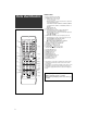
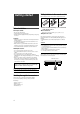
Remote control Parts identification 1 DVR DVD TEST A/V CONTROL RECEIVER STANDBY/ON *FRONT L *FRONT R AUDIO 1 3 2 EFFECT *CENTER *SUBWFR 2 4 5 6 C.TONE *SURR L *SURR R 7 8 9 DVR/DVD *D.
See pages in parentheses for details.
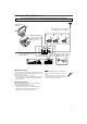
Getting started Putting batteries in the remote control Before using the remote control, put two supplied batteries first. 1 Before Installation General precautions • Be sure your hands are dry. • Turn the power off to all components. • Read the manuals supplied with the components you are going to connect. Locations • Install the receiver in a location that is level and protected from moisture and dust. • The temperature around the receiver must be between –5˚C and 35˚C (23˚F and 95˚F).
Connecting the FM and AM antennas Do not connect the AC power plug to the wall outlet until all connections are completed. AM loop antenna (supplied) If FM reception is poor, connect an outdoor FM antenna (not supplied). Snap the tabs on the loop into the slots of the base to assemble the AM loop antenna. AM LOOP If AM reception is poor, connect an outdoor single vinyl-covered wire (not supplied).
Connecting the speakers Do not connect the AC power plug to the wall outlet until all connections are completed.
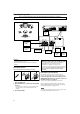
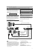
Connecting video components Do not connect the AC power plug to the wall outlet until all connections are completed. This receiver is equipped with the following video terminals— composite video, S-video, and component video terminals. • If your video components have S-video (Y/C-separation) and/or component video (Y, PB, PR) jacks, connect them using an Svideo cable (not supplied) or component video cable (not supplied).
Do not connect the AC power plug to the wall outlet until all connections are completed. 7 Connecting a VCR Turn off all components before making connections. • When you connect other components, refer also to their manuals.
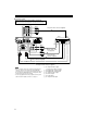
Do not connect the AC power plug to the wall outlet until all connections are completed. 7 Connecting a DBS tuner Turn off all components before making connections. • When you connect other components, refer also to their manuals.
Digital connection This receiver is equipped with two DIGITAL IN terminals—one digital coaxial terminal and one digital optical terminal. To reproduce the digital sound, use the digital connection in addition to the analog connection methods described on pages 7 to 9. Digital coaxial cable (not supplied) USB Connection This receiver is equipped with a USB terminal on the front panel. You can connect your PC to this terminal and enjoy sound reproduced through your PC.
5. The USB drivers are installed automatically. • If the USB drivers are not installed automatically, install the USB drivers by following the instructions on the PC’s monitor. 6. Check if the drivers are correctly installed. 1. Open the Control Panel on your PC: Select [Start] = [Control Panel]. 2. Select [System] = [Hardware] = [Device Manager] = [Sound, video and game controllers] = [Universal Serial Bus controllers]. • The following window appears, and you can check whether the drivers are installed.
2 Select the source to play Basic operations On the front panel: Turn SOURCE SELECTOR until the source name you want appears on the display. The source lamp corresponding to the selected source lights in red. • As you turn SOURCE SELECTOR, the source changes as follows: ANALOG AUTO SURR L TUNED STEREO AUTO MUTING R S.
DGTL AUTO (DIGITAL AUTO): Select for the digital input mode. The receiver automatically detects the incoming signal format, then the digital signal format indicator (LINEAR PCM, 3 Adjust the volume DOLBY DIGITAL*: Select to play back software encoded with Dolby Digital. To increase the volume, turn MASTER VOLUME control clockwise (or press VOLUME + on the remote control). To decrease the volume, turn MASTER VOLUME control counterclockwise (or press VOLUME – on the remote control).
Turning off the sounds temporarily From the remote control ONLY: Press MUTING to turn off the sound through all connected speakers and headphones. “MUTING” appears on the display and the volume turns off. ANALOG AUTO SURR L R S.WFR To restore the sound, press MUTING again. • Pressing VOLUME +/– (or turning MASTER VOLUME control on the front panel) also restores the sound.
3 Turn MULTI JOG to select an appropriate Basic settings number of the connected speakers (speaker channel number). As you turn the jog, the speaker channel number changes as follows. • For the details of speaker channel number, see “ Speakers (channels) number and the size” on page 16. ANALOG L R S.WFR To obtain the best possible sound effect from Surround/DSP modes (see pages 27 to 31), you need to set up the speaker and subwoofer information after all the connections are completed.
Speakers (channels) number and the size You can find how each of the speaker size is defined according to the number of connected speakers (speaker channel “ch” number) you select. • Subwoofer is counted as 0.1 channel. The size of connected speakers SUBWFR Basic setting items You can adjust the following items. See pages in parentheses for details. • You cannot select the items which is not available with the current setting. For example, when the speaker channel number is set to “<5.
Operating procedure Setting the speakers 3,5 2,4 1,7 To obtain the best possible surround effect from the Surround and DSP modes, register the setting about the speaker after all connections are completed. • If you have used Quick Speaker Setup on page 15, this setting is not required. Setting subwoofer information—SUBWOOFER On the front panel ONLY: Select whether you have connected a subwoofer or not. Before you start, remember... There is a time limit in doing the following steps.
Setting the speaker distance The distance from your listening point to the speakers is one of the important elements to obtain the best possible sound effect from the Surround/DSP modes. By referring to the speaker distance, the receiver automatically sets the delay time of the sound through each speaker so that sounds through all the speakers can reach you at the same time. If you have used Quick Speaker Setup on page 15, this setting is not required.
Setting the crossover frequency—CROSSOVER Selecting the main or sub channel —DUAL MONO You can select the playback sound (channel) you want while playing digital software recorded (or broadcasted) in Dual Mono mode (see page 28), which includes two monaural channels separately. When the receiver detects Dual Mono signals, the DUAL MONO indicator lights up on the display. D MONO Select to play back the main channel (Ch 1).* Signal indicator “L” lights up while playing back this channel.
Setting the digital input (DIGITAL IN) terminals—DIGITAL IN 1/2 For the VCR (VCR VIDEO IN): VCR Select when connecting the VCR to the composite video or S-video input jacks. When you use the digital input terminals, register what components are connected to which terminals—DIGITAL IN 1/2 (see page 10) so that the correct source name will appear when you select the digital source.
Sound adjustments Operating procedure 3,5 2,4 1,7 On the front panel: You can make sound adjustment to your preference after completing basic setting. Basic adjustment items Before you start, remember... There is a time limit in doing the following steps. If the setting is canceled before you finish, start from step 1 again. Ex.: When adjusting subwoofer output level. You can adjust the following items. See pages in parentheses for details.
Adjusting the speaker output levels • • • • • • • • SUBWFR LVL (subwoofer output level), FRONT L LVL (left front speaker output level), FRONT R LVL (right front speaker output level), CENTER LVL (center speaker output level), SURR L LVL (left surround speaker output level), SURR R LVL (right surround speaker output level), S BACK L LVL (left surround back speaker output level), S BACK R LVL (right surround back speaker output level) You can adjust the speaker output levels.
Adjusting the bass sounds Reinforcing the bass—BASS BOOST You can boost the bass level—Bass Boost. • Once you have made an adjustment, it is memorized for each source. • You cannot use the remote control for this setting. B BOOST Select to boost the bass level. The B.BOOST indicator lights up on the display. B BOOST Select to deactivate the Bass Boost. From the remote control: Press SOUND, then EFFECT to select the level you want to adjust.
Adjusting the center channel localization for Pro Logic IIx Music and Pro Logic II Music—CENTER WIDTH This setting is available when Pro Logic IIx Music or Pro Logic II Music is activated for the analog or digital 2-channel sound signal. To activate Pro Logic IIx Music or Pro Logic II Music, see page 31. • If “CENTER SPK” is set to “NO” (see page 17), this item is not adjustable. • Once you have made an adjustment, it is memorized until you change the setting.
Tuner operations Tuning in to stations manually From the remote control ONLY: 1 Press FM/AM to select the band. The last received station of the selected band is tuned in. • Each time you press the button, the band alternates between FM and AM. ANALOG TUNED STEREO AUTO MUTING L R S.WFR MHz Tuner operations are mainly done from the remote control. 2 Press repeatedly or hold TUNING 9 or ( TUNING until the station you want is tuned in. • Pressing (or holding) TUNING 9 increases the frequency.
3 Press the numeric buttons (1 – 10, +10) to On the front panel: select a channel number while the channel number position is flashing. 2 1,3 • For channel number 5, press 5. • For channel number 15, press +10, then 5. • For channel number 30, press +10, +10, then 10. ANALOG TUNED STEREO L Before you start, remember... AUTO MUTING R S.WFR MHz There is a time limit in doing the following steps. If the setting is canceled before you finish, start from step 2 again.
Creating realistic sound fields Introducing the Surround modes ■ Dolby Digital* Dolby Digital is a digital signal compression method, developed by Dolby Laboratories, and enables multi-channel encoding and decoding. • When Dolby Digital signal is detected through the digital input, the indicator lights up on the display. Dolby Digital 5.1CH Reproducing theater ambience In a movie theater, many speakers are located on the walls to reproduce impressive multi-channel sound, reaching you from all directions.
Dolby Pro Logic IIx DTS Neo:6 Dolby Pro Logic IIx is a newly introduced multi-channel playback format to convert not only multi-channel software but 2-channel software into 7.1 channel (or 6.1 channel) that developed from Dolby Pro Logic II. The matrix-based conversion method used for Dolby Pro Logic IIx makes no limitation for the cutoff frequency of the surround treble.
Introducing the DSP modes The sound heard in a concert hall, club, etc. consists of direct sound and indirect sound—early reflections and reflections from behind. Direct sounds reach the listener directly without any reflection. On the other hand, indirect sounds are delayed by the distances of the ceiling and walls. These direct sounds and indirect sounds are the most important elements of the acoustic surround effects.
Using the Surround/DSP modes Available Surround/DSP modes vary depending on the speaker settings and the incoming signals. See the table below. • The numbers inside the parentheses following the incoming signal type indicate the number of the front channels and that of the surround channels. For example, (3/2) indicates that the signals are encoded with three front signals (left/right/center) and two (stereo) surround signals. • For EX/ES/PLIIx setting, see page 18.
Activating the Surround/DSP modes On the front panel: 2 1,3 Available Surround/DSP modes vary depending on the speaker settings and the incoming signals. For details, see page 30. Activating one of the Surround/DSP modes automatically recalls the memorized settings and adjustments. • To adjust the speaker output level, see page 22. • When activating one of the Surround/DSP modes, you can adjust CENTER TONE.
Connections 2: Video cable connection AV COMPU LINK remote control system The AV COMPU LINK remote control system allows you to operate JVC’s video components (TV, DVD player*, and VCR) through this receiver. This receiver is equipped with the AV COMPU LINK-III, which has added a function to operate JVC’s video components through the component video jacks.
Connecting procedure 1 If you have already plugged your VCR, DVD player, TV, and this receiver into the AC outlets, unplug their AC power cords first. 2 Connect your VCR, DVD player, TV, and this receiver as follows, using the cables with the monaural mini-plugs (not supplied). • See “Connections 1” on the previous page. 3 Connect the audio input/output jacks on the VCR, DVD player, TV, and this receiver using the audio cables. • See pages 7 to 9.
Operating other JVC products 7 VCR 1 2 4 5 3 6 7 8 9 10 0 10 You can use the supplied remote control to operate not only this receiver but also other JVC products. • Refer also to the manuals supplied with the other products. – Some JVC VCRs can accept two types of the control signals—remote codes “A” and “B.” This remote control can operate a VCR whose remote control code is set to “A.” – Some JVC DVD recorders can accept four types of the control signals.
7 DVD recorder or DVD player You can always perform the following operation: STANDBY/ON DVD/DVR: DVR 1 2 DVD 3 4 5 6 7 8 9 10 0 10 DVR DVD Turn on or off the DVD recorder or DVD player. To operate the DVD recorder, set the mode selector to “DVR.” After pressing DVR/DVD, you can perform the following operations on the DVD recorder and DVD player. 3: Start playback. To operate the DVD player, set the mode selector to “DVD.” 7: Stop playback. 8: Pause playback. To release it, press 3.
Manufacturers’ codes for TV Operating other manufacturers’ products By changing the transmittable signals, you can use the supplied remote control to operate other manufacturers’ products. • Refer also to the manuals supplied with the other products. • To operate those components with the remote control, first you need to set the manufacturers’ codes each for the TV, VCR, CATV converter, DBS tuner, and DVD player. • After replacing batteries of the remote control, set the manufacturers’ codes again.
❏ Changing the transmittable signals for operating a VCR 1 Press and hold STANDBY/ON VCR. 2 Press VCR. 3 Enter the manufacturer’s code using buttons 1 – 9, and 0. See “Manufacturers’ codes for VCR” on the right. 4 Release STANDBY/ON VCR. Now, you can perform the following operation on the VCR. STANDBY/ON VCR: Turn on or off the VCR. After pressing VCR, you can perform the following operations on the VCR. CHANNEL +/–: Change the channel numbers on the VCR. 3: Start playback. 7: Stop playback.
❏ Changing the transmittable signals for operating a CATV converter or DBS tuner ❏ Changing the transmittable signals for operating a DVD player 1 Press and hold STANDBY/ON 1 Set the mode selector to “DVD.” TV/DBS/ CATV. 2 Press DBS. 3 Enter the manufacturer’s code using buttons 1 – 9, and 0. See “Manufacturers’ codes for CATV converter/DBS tuner” below. 4 Release STANDBY/ON TV/DBS/CATV. After pressing DBS, you can perform the following operations on the CATV converter or DBS tuner.
Troubleshooting Use this chart to help you solve daily operational problems. If there are any problems you cannot solve, contact your JVC’s service center. PROBLEM SOLUTION The power cord is not plugged in. Plug the power cord into an AC outlet. The receiver turns off (enters standby mode). Speakers are overloaded because of high volume. 1. Stop the playback source. 2. Turn on the receiver again, then turn the volume down. Speakers are overloaded because of a short circuit at the speaker terminals.
Specifications Video Video Input Sensitivity/Impedance: Composite video: DVR/DVD, VCR, DBS: 1 V(p-p)/75 Ω S-video: DVR/DVD, VCR, DBS: Y (luminance): 1 V(p-p)/75 Ω C (chrominance, burst): 0.286 V(p-p)/75 Ω Component: DVR/DVD, VCR (DBS): Designs and specifications are subject to change without notice. Y (luminance): 1 V(p-p)/75 Ω PB, PR: 0.
RX-D201S / RX-D202B AUDIO / VIDEO CONTROL RECEIVER EN © 2005 Victor Company of Japan, Limited 0205RYMMDWJEIN