AUDIO/VIDEO CONTROL RECEIVER RX-D411S INSTRUCTIONS LVT1572-003A [B] Cover[B].indd 1 06.6.
Warnings, Cautions, and Others IMPORTANT for the U.K. DO NOT cut off the mains plug from this equipment. If the plug fitted is not suitable for the power points in your home or the cable is too short to reach a power point, then obtain an appropriate safety approved extension lead or consult your dealer. BE SURE to replace the fuse only with an identical approved type, as originally fitted.
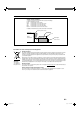
Caution: Proper Ventilation To avoid risk of electric shock and fire and to protect from damage. Locate the apparatus as follows: Front: No obstructions open spacing. Sides: No obstructions in 15 cm from the sides. Top: No obstructions in 15 cm from the top. Back: No obstructions in 15 cm from the back. Bottom: No obstructions, place on the level surface. In addition, maintain the best possible air circulation as illustrated.
SAFETY INSTRUCTIONS “SOME DOS AND DON’TS ON THE SAFE USE OF EQUIPMENT” This equipment has been designed and manufactured to meet international safety standards but, like any electrical equipment, care must be taken if you are to obtain the best results and safety is to be assured. ✮✮✮✮✮✮✮✮✮✮✮✮✮✮✮✮✮✮✮✮✮✮✮✮✮✮✮✮✮✮✮✮✮✮✮✮✮✮✮✮✮✮✮✮✮✮✮ Do read the operating instructions before you attempt to use the equipment.
Introduction We would like to thank you for purchasing one of our JVC products. Before operating this unit, read this manual carefully and thoroughly to obtain the best possible performance from your unit, and retain this manual for future reference. Features DCDi technology RX-D411S features the JVC-exclusive Hybrid Feedback Digital Amplifier. Premium-grade parts and devices, and special internal construction assure you will enjoy superior sound.
Basic settings .............................................................29 Table of Contents Parts identification ......................................................3 Getting started ............................................................6 Before installation .............................................................................6 Checking the supplied accessories .............................................6 Putting the batteries in the remote control .............................
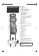
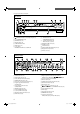
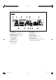
Parts identification To open the cover of the remote control, push here then slide downward. 7 Remote control See pages in parentheses for details.
See pages in parentheses for details.
See pages in parentheses for details.
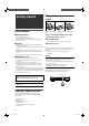
Getting started Putting the batteries in the remote control 1 2 3 Before installation Before using the remote control, put two supplied batteries first. 7 General precautions 1 Press and slide the battery cover on the • Be sure your hands are dry. • Turn the power off to all components. • Read the manuals supplied with the components you are going to connect. 7 Locations • Install the receiver in a location that is level and protected from moisture and dust.
Connecting the FM and AM (MW) antennas Do not connect the AC power cord until all other connections have been made. AM (MW) loop antenna (supplied) If FM reception is poor, connect an outdoor FM antenna (not supplied). Snap the tabs on the loop into the slots of the base to assemble the AM (MW) loop antenna. Black White If AM (MW) reception is poor, connect an outdoor single vinyl-covered wire (not supplied).
Connecting the speakers Do not connect the AC power cord until all other connections have been made. 7 Speaker Layout Diagram SW Powered subwoofer (SW) Left surround back speaker (SBL)* C FL Right surround back speaker (SBR) FR SL Center speaker (C) SR Right surround speaker (SR) SBL (SB*) Left surround speaker (SL) SBR CAUTIONS: • Use speakers with the SPEAKER IMPEDANCE indicated by the speaker terminals (6 Ω – 16 Ω). • DO NOT connect more than one speaker to one speaker terminal.
Connecting video components Do not connect the AC power cord until all other connections have been made. 7 HDMI connection IMPORTANT: The HDMI video signals from the HDMI terminals are transmitted only through the HDMI MONITOR OUT terminal.
Do not connect the AC power cord until all other connections have been made. 7 SCART connection You can enjoy pictures and sounds from playback components simply by connecting with the SCART cable. CAUTION: If you connect a sound-enhancing device such as a graphic equalizer between the source components and this receiver, the sound output through this receiver may be distorted. Turn off all components before making connections. • When you connect the components, refer also to their manuals.
7 Audio/video connection IMPORTANT: In addition to the HDMI terminals and SCART terminals, this receiver is equipped with three video terminals—composite video, S-video, and component video terminals, and two audio jacks—analog discrete 5.1 channel audio input jacks (DVD MULTI IN) and stereo audio jacks. • If your video components have S-video (Y/C-separation) and/or component video (Y, PB, PR) jacks, connect them using an S-video cable (not supplied) or component video cable (not supplied).
Do not connect the AC power cord until all other connections have been made. Connecting a DVD recorder or DVD player with its analog discrete output jacks (DVD MULTI IN): If your DVD recorder or DVD player has analog 5.1 channel output jacks, use the connection below. When a DVD-Audio disc is played back, the original high-quality multi-channel sounds can be reproduced by using this connection. Turn off all components before making connections.
Do not connect the AC power cord until all other connections have been made. Turn off all components before making connections. • When you connect the components, refer also to their manuals. Connecting a VCR and another video component: : signal flow Green Component video cable (not supplied) Blue Red VCR DBS tuner, etc.
7 Digital audio connection This receiver is equipped with three DIGITAL IN terminals— one digital coaxial terminal and two digital optical terminals— and one DIGITAL OUT terminal. To reproduce the digital sound, use the digital audio connection in addition to the analog audio connection methods described on pages 11 to 13. Digital output terminal: You can connect any digital components which have an optical digital input terminal.
5 Check if the drivers are correctly USB connection installed. This receiver is equipped with a USB terminal on the front panel. You can connect your PC to this terminal and enjoy sound reproduced through your PC. When you connect your PC for the first time, follow the procedure below. • Remember you cannot send any signal or data to your PC from this receiver. 1. Open the Control Panel on your PC: Select [Start] = [Control Panel]. 2.
Precise Surround Setup By using Precise Surround Setup, you can optimize the speaker settings easily, quickly and systematically without troublesome adjustments. To obtain the best possible sound effect from the Surround/ DSP modes, set up the speaker and subwoofer information after all the connections are completed.
3 Put on the microphones. • Insert the microphone with “L” into your left ear, the microphone with “R” your right ear. Example: Microphone with “L” Precise Surround Setup starts detecting the speaker and subwoofer information. • When starting Precise Surround Setup, the muting mode and Dimmer are automatically canceled. • “MEASURING 1” flashes on the display.
6 Unplug the earphone-type microphones. • When unplugging the microphones, pull on the plug, not the cord itself. NOTES • Do not press any buttons on the remote control or the front panel of the receiver during Precise Surround Setup; otherwise, the receiver stops setting and returns to the normal operation mode. – After “COMPLETE” is displayed, the Precise Surround Setup results are applied to the speaker settings.
Troubleshooting for Precise Surround Setup When problems occur, a message appears on the display during Precise Surround Setup. In this case, refer to the following solution, then perform Precise Surround Setup again. • To restart Precise Surround Setup, press PSS on the remote control; however, when you have turned the receiver off for the solution, start from step 2 again. Error message Possible cause Solution Headphones are connected to the PHONES jack. Unplug the headphones.
Basic operations 2 Select the source to play On the front panel: Turn SOURCE SELECTOR until the source name you want appears on the display. The source lamp corresponding to the selected source lights in red. • As you turn SOURCE SELECTOR, the source changes as follows: 1 2 3 DVR/DVD Ô VCR Ô VIDEO Ô TV Ô USB Ô FM Ô AM Ô (Back to the beginning) Source lamps 1 2 3 DVR/DVD: VCR: VIDEO: TV: USB: FM: AM: Select this for the DVD recorder or DVD player. Select this for the VCR.
7 Listening with headphones You can enjoy not only stereo software but also multi-channel software through the headphones. (Sounds are down-mixed to the front channels while playing multi-channel software.) Connect a pair of headphones to the PHONES jack on the front panel to activate the HEADPHONE mode. The HEADPHONE indicator lights up on the display. • You can also enjoy the Surround/DSP mode through the headphones—3D HEADPHONE mode (see page 42).
Selecting the digital decode mode Turning off the sounds temporarily When “HDMI” or “DIGITAL” is selected for the audio input setting (see page 21), this receiver automatically detects the incoming digital signal format and sets the digital decode mode to “DIGITAL AUTO.” • The DIGITAL AUTO indicator lights up on the display. From the remote control ONLY: Press MUTING to turn off the sound through all connected speakers and headphones.
Turning off the power with the Sleep Timer You can fall asleep while listening to music—Sleep Timer. From the remote control ONLY: Press SLEEP repeatedly. • Each time you press the button, the shut-off time changes in 10-minute intervals. The SLEEP indicator lights up on the display. SLEEP indicator 10min = 20min = 30min = 40min =50min = 60min = 70min = 80min =90min = OFF (Canceled) = (Back to the beginning) When the shut-off time comes: The receiver turns off automatically.
Tuner operations Tuning in to stations manually From the remote control ONLY: 1 Press FM/AM to select the band. The last received station of the selected band is tuned in. • Each time you press the button, the band alternates between “FM” and “AM.” Tuner operations are mainly done from the remote control. 2 Press repeatedly or hold TUNING 9 or ( TUNING until the station you want is tuned in. • Pressing (or holding) TUNING 9 increases the frequency.
3 Press the numeric buttons (0 – 9, h10) On the front panel: 2 1, 3 to select a channel number while the channel number position is flashing. • For channel number 5, press 5. • For channel number 10, press h10, 1, then 0. • For channel number 25, press h10, 2, then 5. Before you start, remember... There is a time limit in doing the following steps. If the setting is canceled before you finish, start from step 2 again. 4 Press MEMORY again while the selected channel number is flashing on the display.
Using the Radio Data System to receive FM stations Only the buttons on the remote control are used for Radio Data System operations. Radio Data System allows FM stations to send an additional signal along with their regular program signals. For example, the stations send their station names, as well as information about what type of program they broadcast, such as sports or music, etc.
PTY codes Finance: Stock Market reports, commerce, trading, etc. News Ô Affairs Ô Info Ô Sport Ô Educate Ô Drama Ô Culture Ô Science Ô Varied Ô Pop M Ô Rock M Ô Easy M Ô Light M Ô Classics Ô Other M Ô Weather Ô Finance Ô Children Ô Social Ô Religion Ô Phone In Ô Travel Ô Leisure Ô Jazz Ô Country Ô Nation M Ô Oldies Ô Folk M Ô Document Ô TEST Ô Alarm ! Ô None Ô (Back to the beginning) Children: Programs targeted at a young audience.
Switching to broadcast program of your choice temporarily Another convenient Radio Data System service is called “Enhanced Other Networks.” This allows the receiver to switch temporarily to a broadcast program of your choice (TA, NEWS, and/or INFO) from a different station except in the following case: • The Enhanced Other Networks mode only works when receiving an FM station with the Enhanced Other Networks code. Before you start, remember...
Basic settings To obtain the best possible sound effect from the Surround/ DSP modes (see pages 39 to 44), you need to set up the speaker and subwoofer information after all the connections are completed. From pages 29 to 34, how to set speakers and other basic items of the receiver are explained. Items EX/ES/PLIIx* To do 2 Select the EX/ES/PLIIx reproduction mode. (31) DUAL MONO Select the Dual Mono sound channel. (32) SUBWOOFER OUT Select sounds emitted from the subwoofer.
Operating procedure 1, 7 3, 5 Setting the speakers 2, 4 On the front panel ONLY: Before you start, remember... There is a time limit in doing the following steps. If the setting is canceled before you finish, start from step 1 again. Ex.: When setting the DIGITAL IN 1 terminal To obtain the best possible surround effect from the Surround and DSP modes, register the setting about the speaker after all connections are completed.
7 Setting the speaker distance The distance from your listening position to the speakers is one of the important elements to obtain the best possible sound effect from the Surround/DSP modes. By referring to the speaker distance, the receiver automatically sets the delay time of the sound through each speaker so that sounds through all the speakers can reach you at the same time. • Measuring unit—DIST UNIT Select which measuring unit you use. D UNIT meter Select to set the distance in meters.
Selecting the main or sub channel— DUAL MONO You can select the playback sound (channel) you want while playing digital software recorded (or broadcasted) in Dual Mono mode (see page 41), which includes two monaural channels separately. When the receiver detects Dual Mono signals, the DUAL MONO indicator lights up on the display. • You cannot adjust directly from the remote control. D MONO MAIN Select to play back the main channel (Ch 1).* Signal indicator “L” lights up while playing back this channel.
7 Setting the low frequency effect attenuator —LFE ATT If the bass sound is distorted while playing back software encoded with Dolby Digital or DTS, set the LFE level to eliminate distortion. • This function takes effect only when the LFE signals come in. LFE 0dB Normally select this. LFE –10dB Select when the bass sound is distorted. Initial setting: 0 dB Using the Midnight mode— MIDNIGHT MODE You can enjoy a powerful sound at night using the Midnight mode.
Selecting the source for HDMI terminal and COMPONENT VIDEO jacks—HDMI SELECT/CMPNT SELECT When you connect a video component other than DVD recorder and DVD player to the HDMI VIDEO(VCR) IN terminal or COMPONENT VIDEO jacks on the rear of the receiver, you need to select either “VIDEO” or “VCR” for each terminal according to the component you connect. If you have not selected an appropriate source, you cannot view the playback picture on the TV. • You cannot adjust directly from the remote control.
NOTE Sound adjustments Some items are not available in the following cases below: – When selecting “A MULTI” for the audio input setting (see page 12) – When multi-channel PCM signals (see page 41) are coming in with selecting “HDMI” for the audio input setting (see page 12) Operating procedure On the front panel: 1, 7 You can make sound adjustment to your preference after completing basic setting. 3, 5 2, 4 Basic adjustment items You can adjust the following items.
Adjusting the speaker output levels • • • • • • • • • SUBWFR LVL (subwoofer output level) FRONT L LVL (left front speaker output level) FRONT R LVL (right front speaker output level) CENTER LVL (center speaker output level) SURR L LVL (left surround speaker output level) SURR R LVL (right surround speaker output level) S BACK LVL (surround back speaker output level) S BACK L LVL (left surround back speaker output level) S BACK R LVL (right surround back speaker output level) You can adjust the speaker out
Reinforcing the bass—BASS BOOST You can boost the bass level—Bass Boost. • Once you have made an adjustment, it is memorized for each source. B BOOST ON Select to boost the bass level. The B.BOOST indicator lights up on the display. B BOOST OFF Select to deactivate the Bass Boost. Initial setting: OFF 7 Adjusting the effect level for DSP modes— EFFECT This setting is available only when one of the DSP modes (except All Channel Stereo) is in use. To activate DSP mode, see pages 43 and 44.
7 Adjusting the panorama control for Pro Logic IIx Music and Pro Logic II Music—PANORAMA 7 Adjusting the sound localization of the center channel—CENTER GAIN This setting is available when Pro Logic IIx Music or Pro Logic II Music is activated for the analog or digital 2-channel sound signal. To activate Pro Logic IIx Music or Pro Logic II Music, see pages 43 and 44. • Once you have made an adjustment, it is memorized until you change the setting. • You cannot adjust directly from the remote control.
Creating realistic sound fields Introducing the Surround modes 7 Dolby Digital* Dolby Digital is a digital signal compression method, developed by Dolby Laboratories, and enables multi-channel encoding and decoding. • When Dolby Digital signal is detected through the digital input, the indicator lights up on the display. Dolby Digital 5.1CH Reproducing theater ambience In a movie theater, many speakers are located on the walls to reproduce impressive multi-channel sound, reaching you from all directions.
Dolby Pro Logic IIx DTS 96/24 Dolby Pro Logic IIx is another multi-channel playback decoder to convert not only multi-channel software but 2-channel software into 7.1 channel (or 6.1 channel) that developed from Dolby Pro Logic II. The matrix-based conversion method used for Dolby Pro Logic IIx makes no limitation for the cutoff frequency of the surround treble.
7 Digital Acoustic Processor (DAP) modes About other digital signals Linear PCM—Uncompressed digital audio data used for DVDs, CDs, and Video CDs DVDs support 2 channels with sampling rates of 48/96 kHz, at quantization of 16/20/24 bits. On the other hand, CDs and Video CDs are limited to 2 channels with 44.1 kHz at 16 bits. • When Linear PCM signal is detected, the LINEAR PCM indicator lights up.
7 All Channel Stereo mode (ALL CH STEREO) 3D HEADPHONE mode This mode can reproduce a larger stereo sound field using all the connected (and activated) speakers. This mode cannot be used if “SURROUND SPK” is set to “NO” in the speaker setting (see page 30). Sound reproduced from normal stereo If you connect a pair of headphones while one of the Surround/DSP modes is in use, the 3D HEADPHONE mode is activated without respect to the type of software played back.
7 About the DSP modes • The following DSP modes are available regardless of incoming signal type: HALL1, HALL2, LIVE CLUB, DANCE CLUB, PAVILION, THEATRE1, THEATRE2 • If multi-channel (more than 2 channels) digital signals are coming in, “MONO FILM” is not available. • If “SURROUND SPK” is set to “NO,” “ALL CH STEREO” is not available. Virtual Surround Back If you have connected (and activated) the surround speakers, you can use Virtual Surround Back.
7 Selecting the Surround/DSP modes On the front panel: 2 From the remote control: 1, 3 1 Before you start, remember... There is a time limit in doing the following steps. If the setting is canceled before you finish, start from step 2 again. 2 1 Select and play any source. • Surround/DSP modes are not available when multichannel PCM (see page 41) signals recorded in DVDAudio are coming in. See page 12 for details.
Operating other JVC products 7 VCR You can use the supplied remote control to operate not only this receiver but also other JVC products. • Refer also to the manuals supplied with the other products. – Some JVC VCRs can accept two types of the control signals—remote codes “A” and “B.” This remote control can operate a VCR whose remote control code is set to “A.” – Some JVC DVD recorders can accept four types of the control signals. Select an appropriate code for your DVD recorder (see page 46).
7 DVD recorder or DVD player You can always perform the following operation: DVR/DVD To operate the DVD recorder, set the mode selector to “DVR.” To operate the DVD player, set the mode selector to “DVD.” : Turn on or off the DVD recorder or DVD player. After pressing DVR/DVD, you can perform the following operations on the DVD recorder and DVD player. 3: Start playback. 7: Stop playback. 8: Pause playback. To release it, press 3. ¢: Skip to the beginning of the next chapter.
Manufacturer codes for TV: Operating other manufacturers’ products Manufacturer By changing the transmittable signals, you can use the supplied remote control to operate other manufacturers’ products. • Refer also to the manuals supplied with the other products. • To operate those components with the remote control, first you need to set the manufacturer codes each for the TV, VCR, STB, and DVD player. • After replacing the batteries of the remote control, set the manufacturer codes again.
To change the transmittable signals for operating a VCR 1 Press and hold VCR . • Keep the button pressed until step 3 is finished. 2 Press VCR. 3 Enter the manufacturer code using the Manufacturer codes for VCR: Manufacturer Codes JVC 01 Akai 02, 36 Bell+Howell 03, 16 Blaupunkt 04 numeric buttons (1 – 9, 0). CGM 03, 05, 16 See “Manufacturer codes for VCR” on the right. Daewoo 34 4 Release VCR . Now, you can perform the following operation on the VCR: VCR : Turn on or off the VCR.
To change the transmittable signals for operating a STB 1 Press and hold STB . • Keep the button pressed until step 3 is finished. 2 Press STB CONT. 3 Enter the manufacturer code using the To change the transmittable signals for operating a DVD player 1 Set the mode selector to “DVD.” 2 Press and hold DVR/DVD . • Keep the button pressed until step 4 is finished. numeric buttons (1 – 9, 0). 3 Press DVR/DVD. See “Manufacturer codes for STB” below.
Troubleshooting Use this chart to help you solve daily operational problems. If there are any problems you cannot solve, contact your JVC service center. For Precise Surround Setup, see the separated troubleshooting on pages 19. PROBLEM SOLUTION The power does not come on. The power cord is not plugged in. Plug the power cord into an AC outlet. The receiver turns off (enters standby mode). Speakers are overloaded because of high volume. 1. Stop the playback source. 2.
Remote control PROBLEM POSSIBLE CAUSE SOLUTION The remote control does not operate as you intend. The remote control is not ready for your intended operation. Set the mode selector correctly, then press the corresponding source selecting button before operation. The remote control does not work. There is an obstruction blocking the remote sensor on the receiver. Remove the obstruction. Tuner Continuous hiss or buzzing during FM reception. Occasional cracking noise during FM reception.
Video Specifications Designs and specifications are subject to change without notice. 7 Amplifier Output Power At stereo operation: Front channels: 120 W per channel, min. RMS, driven into 6 Ω at 1 kHz with no more than 10% total harmonic distortion. At surround operation: Front channels: 110 W per channel, min. RMS, driven into 6 Ω at 1 kHz with no more than 0.8% total harmonic distortion. Center channel: 110 W, min. RMS, driven into 6 Ω at 1 kHz, with no more than 0.8% total harmonic distortion.
RX-D411S AUDIO/VIDEO CONTROL RECEIVER EN © 2006 Victor Company of Japan, Limited Cover[B].indd 2 0606RYMMDWJEIN 06.6.