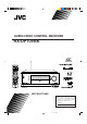
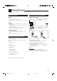
AUDIO/VIDEO CONTROL RECEIVER RX-DP10VBK LEARN TRANSMIT STANDBY MAIN ROOM SUB ROOM MAIN ROOM SUB ROOM ON/OFF ON TV/CATV/DBS VCR 1 STANDBY/ON STANDBY/ON ON/OFF MAIN ROOM SUB ROOM LEARN DVD MULTI PHONO CD VCR 1 VCR 2 TAPE/MD CDR TV/DBS DVD VIDEO FM 1 2 AM ANALOG/DIGITAL EFFECT INPUT 3 ROOM SIZE SOUND 4 5 6 LIVENESS 7/P 8 10 0 RETURN FM MODE 9 WALL TEST +10 MASTER VOLUME 100+ SURROUND DSP THX ON/OFF MODE ON/OFF STANDBY SLEEP DIMMER TV CATV/ DBS / REW PLAY
Warnings, Cautions and Others CAUTION RISK OF ELECTRIC SHOCK DO NOT OPEN CAUTION: TO REDUCE THE RISK OF ELECTRIC SHOCK. DO NOT REMOVE COVER (OR BACK) NO USER SERVICEABLE PARTS INSIDE. REFER SERVICING TO QUALIFIED SERVICE PERSONNEL. The lightning flash with arrowhead symbol, within an equilateral triangle is intended to alert the user to the presence of uninsulated "dangerous voltage" within the product's enclosure that may be of sufficient magnitude to constitute a risk of electric shock to persons.
Note to CATV system installer: This reminder is provided to call the CATV system installer’s attention to Section 820-40 of the NEC which provides guidelines for proper grounding and, in particular, specifies that the cable ground shall be connected to the grounding system of the building, as close to the point of cable entry as practical. For the main unit: This equipment has been tested and found to comply with the limits for a Class B digital device, pursuant to part 15 of the FCC Rules.
Table of Contents Introduction ................................................ 2 Features ...................................................................................... 2 Precautions ................................................................................. 2 Parts Identification ...................................... 3 Getting Started ........................................... 6 Before Installation ......................................................................
Introduction We would like to thank you for purchasing one of our JVC products. Before operating this unit, read this manual carefully and thoroughly to obtain the best possible performance from your unit, and retain this manual for future reference. Features Precautions THX Surround EX (DTS-ES compatible) THX Surround EX is a format that has additional left and right surround back channels on the basis of Dolby Digital 5.1 channels.
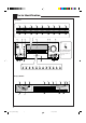
Parts Identification Front Panel 1 2 3 4 5 6 7 8 9 SPEAKERS 1 INPUT MODE / INPUT ATT SURROUND ON / OFF DSP MODE SOUND SELECTOR ADJUST MENU DOWN UP SET SPEAKERS 2 / SUB ROOM SUB ROOM CONTROL THX ON / OFF LINE DIRECT FM MODE SETUP MENU LEFT RIGHT EXIT w e r y u i p q o ; t s a d f g h DOOR DOWN MASTER VOLUME STANDBY DIMMER CC CONVERTER STANDBY/ON MAIN ROOM ON/OFF DOOR UP RX-DP10V SUB ROOM ON/OFF DOOR DOWN SPEAKERS 1 INPUT MODE / INPUT ATT SURROUND ON / OFF
Refer to the pages in parentheses for details. Front Panel Display Window 1 2 3 4 5 6 7 8 9 p q w e r t y u i o 1 ANALOG indicator (24) • Lights up when an analog input (source) is selected. 2 DIGITAL AUTO indicator (24) • Lights up when auto digital input (DIGITAL AUTO) is selected. 3 Surround/DSP mode indicators • Indicate the current Surround/DSP mode setting. 4 TUNED indicator (31) • Lights up when a station is received. 5 STEREO indicator (31) • Lights up when an FM stereo station is received.
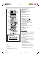
Remote Control LEARN TRANSMIT 1 STANDBY MAIN ROOM SUB ROOM MAIN ROOM SUB ROOM 2 ON/OFF y ON TV/CATV/DBS VCR 1 STANDBY/ON STANDBY/ON u ON/OFF 5 6 7 8 9 p q w MAIN ROOM SUB ROOM LEARN 3 e 4 DVD DVD MULTI PHONO CD VCR 1 VCR 2 TAPE/MD CDR TV/DBS VIDEO FM AM 1 2 ANALOG/DIGITAL 5 6 r t y EFFECT INPUT 3 ROOM SIZE SOUND 4 5 6 LIVENESS 7 8 9 p q 7/P 8 10 0 i u o ; a i 9 WALL TEST +10 RETURN FM MODE 100+ SURROUND DSP THX ON/OFF MODE ON/OFF LINE DIRECT
Getting Started This section explains how to connect audio/video components and speakers to the receiver, and how to connect the power supply. Before Installation General Connecting the FM and AM Antennas FM Antenna Connections • Be sure your hands are dry. • Turn the power off on all components. • Read the manuals supplied with the components you are going to connect. Extend the supplied FM antenna horizontally.
AM Antenna Connections 2 1 Connecting the Speakers 3 ANTENNA AM EXT AM LOOP Turn the loop until you have the best reception. FM 75 COAXIAL You can connect the following speakers: • Two pairs of front speakers to produce normal stereo sound. • One pair of surround speakers to enjoy the surround effect. • One pair of surround back speakers to enjoy 7.1 channel sound reproduction. • One center speaker to produce more effective surround effect (to emphasize human voices).
Basic connecting procedure RIG RIG HT LE You can connect two pairs of front speakers—one pair to the FRONT 1 SPEAKERS terminals, and the other pair to the FRONT 2 / SUB ROOM SPEAKERS terminals. The speakers connected to the FRONT 2 / SUB ROOM SPEAKERS terminals can be used as follows: • As the second front speakers in the main room • As the front speakers in the sub-room when using the Multi-room operations. (See page 17.
Enhance your audio system Connecting Audio/Video Components You can use this receiver as the pre-amplifier (control amplifier) when you connect power amplifiers to the PREOUT jacks on the rear panel, using cables with RCA pin plugs (not supplied). • Connect the white plug to the audio left jack, and the red plug to the audio right jack. Left front speaker Right front speaker You can connect the following audio/video components to this receiver. Refer also to the manuals supplied with your components.
CD recorder CD player AUDIO RIGHT CD recorder LEFT PHONO CD player To audio input To audio output CD AUDIO RIGHT OUT (REC) To audio output LEFT PHONO TAPE MD CD IN (PLAY) OUT (REC) OUT (REC) TAPE MD CDR IN (PLAY) IN (PLAY) FRONT OUT (REC) DVD SUB WOOFER SURR (REAR) CENTER CDR IN (PLAY) FRONT R DVD L DVD SUB WOOFER SURR (REAR) CENTER Cassette deck or MD recorder R DVD L Cassette deck To audio input To audio output AUDIO RIGHT LEFT PHONO If your audio components have a COM
Video component connections Use the cables with RCA pin plugs (not supplied). Connect the white plug to the audio left jack, the red plug to the audio right jack, and the yellow plug to the video jack. • If your video components have S-video (Y/C-separation) and/or component video (Y, PB/CB, PR/CR) jacks, connect them using an S-video cable (not supplied) and/or component video cable (not supplied).
TV and/or DBS tuner AUDIO VIDEO RIGHT VIDEO LEFT COMPONENT S-VIDEO TV SOUND DBS Y OUT (REC) PB/CB VCR1 1(DVD) IN (PLAY) PR/CR OUT (REC) Y When connecting the TV to the AUDIO jacks (TV SOUND/DBS), DO NOT connect the TV’s video output to these video input jacks.
DVD player • When you connect the DVD player with stereo output jacks: AUDIO RIGHT LEFT VIDEO RIGHT VIDEO LEFT TV SOUND DBS PHONO CD OUT (REC) COMPONENT S-VIDEO TAPE MD IN (PLAY) Y OUT (REC) PB/CB VCR1 1(DVD) IN (PLAY) PR/CR OUT (REC) Y VCR2 OUT (REC) IN (PLAY) PB/CB CDR 2 IN (PLAY) FRONT FRONT SUB WOOFER PR/CR DVD MONITOR OUT Y SURR MONITOR OUT PB/CB SURR BACK PREOUT CENTER SUB WOOFER CENTER R R L DVD R PR/CR B MONITOR OUT SUB ROOM L PREOUT A L D C D
Notes: Digital Connections This receiver is equipped with five DIGITAL IN terminals—one digital coaxial terminal and four digital optical terminals—and one DIGITAL OUT terminal. IMPORTANT: • When connecting the DVD player, digital TV broadcast tuner, digital VCR, or DBS tuner using the digital terminals, you also need to connect it to the video terminal on the rear. Without connecting it to the video terminal, you cannot view any playback picture.
The RF rod antenna and IR signal Transmitter Setting Up the RF Rod Antenna The remote control supplied for this receiver can transmit both RF (Radio Frequency) signal as well as IR (infrared) signal. The RF rod antenna can receive the RF signals emitted from the remote control. So, with the RF rod antenna connected, you can operate the receiver at a distance of up to 15 m (50 feet) using RF signals sent from this receiver (more than twice as far as when using IR signals).
3. Connect the plug of the transmitter to the IR OUT jack of the receiver and attach the transmitter. RF Putting Batteries in the Remote Control Before using the remote control, insert the two supplied batteries first. REMOTE Target component(s) ANTENNA 2 1 BAND1 3 LR6(AM3) /L40(15A) BAND2 s es L an th 3 m IR OUT 0 (1 ) et fe At an angle of approx. 60° 1. On the back of the remote control, remove the battery cover.
Multi-Room Operations Before operating this receiver any further, be familiar with this Multi-room function. This function enables you to listen to different sources in two different places (we call these two places “main room” and “sub-room”) by using this receiver. This section explains only the required speaker connections, the concept, and basic operations of the Multi-room function. For more detailed operations, see the respective pages in this manual. Required Connections for Sub-Room 1.
Basic Operating Procedure for Main Room 1. Set MAIN ROOM/SUB ROOM (LEARN/TRANSMIT) selector to “MAIN ROOM.” On the unit: 1. Press From the remote control: (STANDBY/ON). The STANDBY lamp goes off, and the MAIN ROOM ON/OFF lamp lights up. The front door moves down so that the source selecting buttons appear, and the buttons and controls on the unit work for the main room operations. • For more details, see “Turning the Power On and Off (Standby)” on page 20.
Basic Operating Procedure for Sub-Room The sources and functions available for the sub-room operations are limited. For more details on the sub-room operations, see “Sub-Room Operations” on pages 27 to 30. MASTER VOLUME Down Note: On the unit: 1. Press 6. Turn MASTER VOLUME to adjust the volume level of the sound through the sub-room front speakers. (STANDBY/ON). The STANDBY lamp goes off, and the MAIN ROOM ON/OFF lamp lights up.
Main Room Operations This section explains only the operations commonly used when you play any sound source in the main room. See pages 27 to 30 for the sub-room operations. • Before performing main room operations, it is recommended to finish the basic settings on pages 33 to 40. IMPORTANT: To turn off the power (into standby mode), STANDBY press (STANDBY/ON) again. The STANDBY lamp lights up, and the front STANDBY/ON door automatically closes. (The MAIN ROOM ON/OFF and/or SUB ROOM ON/OFF lamp goes off.
Canceling the Main Room Operations Selected source name ANALOG To stop the main room operations and sounds from the main room speakers, press MAIN ROOM ON/OFF so that the MAIN ROOM ON/OFF lamp goes off. MAIN ROOM ON/OFF From the remote control Notes: • If you have turned off the receiver with the volume level set at more than level “–35 dB,” the volume level will be automatically set at level “–35 dB” next time you turn on the receiver.
The signal indicators light up to indicate the incoming signals. L : • When digital input is selected: Lights up when the left channel signal comes in. • When analog input is selected: Always lights up. R : • When digital input is selected: Lights up when the right channel signal comes in. • When analog input is selected: Always lights up. C : Lights up when the center channel signal comes in. LFE : Lights up when the LFE channel signal comes in.
Activating the Main Room Front Speakers When shipped from the factory, both pairs of the front speakers have been set to be used in the main room. • To use the front speakers connected to the FRONT 2/SUB ROOM SPEAKERS terminals in the sub-room, see “Preparing for the Sub-Room Operations—SUB ROOM” on page 40, and “Activating the Sub-Room Front Speakers” on page 30.
DIGITAL AUTO : Select this for the digital input mode. The receiver automatically detects the incoming signals. The DIGITAL AUTO indicator lights up on the display, and the digital signal format indicators for the detected signals also light up. ANALOG : Select this for the analog input mode. The ANALOG indicator lights up. When selecting “DIGITAL AUTO,” the following indicators indicate the digital signal format of the incoming signal.
Making Sounds Natural Changing the Display Brightness You can dim the display. Press DIMMER. • Each time you press the button, the brightness level of the display changes as follows: DIMMER DIMMER JVC’s CC (Compensative Compression) Converter eliminates jitter and ripples, achieving a drastic reduction in digital distortion by processing the digital music data in 24 bit–quantization and by expanding the sampling frequency to 176.4 kHz (for fs 44.1 kHz signals)/192 kHz (for fs 48 kHz signals).
Notes: • Once you change the source name, it is applied both for the main room source and sub-room source. • Without changing the source name, you can still use the connected components. However, there may be some inconvenience. – “TAPE” or “TV” will appear on the display when you select the MD recorder or DBS tuner. – You cannot use the digital input (see page 23) for the MD recorder. – You cannot use the COMPU LINK remote control system (see page 54) to operate the MD recorder.
Sub-Room Operations This section explains only the operations used when you play a sound source in the sub-room. See pages 20 to 26 for the main room operations. • Before performing sub-room operations, it is recommended to finish the basic settings on pages 33 to 40. IMPORTANT: Check to see if the following before or while using the buttons and controls.
To turn off the power (into standby mode), STANDBY (STANDBY/ON) again. press The STANDBY lamp lights up, and the front STANDBY / ON door automatically closes. (The MAIN ROOM ON/OFF and/or SUB ROOM ON/OFF lamp goes off.) • A small amount of power is consumed in standby mode. To turn the power off completely, unplug the AC power cord.
Adjusting the Sub-Room Volume Selecting the Sub-Room Source to Play MASTER VOLUME On the unit: Press one of the source selecting buttons. DVD DVD MULTI VCR 1 VCR 2 TV/DBS VIDEO CD PHONO TAPE/MD CDR FM AM On the unit SPEAKERS 1 To increase the volume, turn MASTER VOLUME clockwise. To decrease the volume, turn it Down counterclockwise. • When you turn MASTER VOLUME rapidly, the volume level also changes rapidly. • When you turn MASTER VOLUME slowly, the volume level also changes slowly.
Activating the Sub-Room Front Speakers This section is NOT applicable to those who connect the subroom front speakers to the SUB ROOM PREOUT jacks using another amplifier (see page 17). Muting the Sub-Room Sound From the remote control ONLY: Press MUTING to mute the sound through the sub-room front speakers. Before you start, remember... • When shipped from the factory, both pairs of the front speakers have been set to be used in the main room.
Receiving Radio Broadcasts You can browse through all the stations or use the preset function to go immediately to a particular station. Indicates the functions YOU CAN ALSO USE when the receiver is ready for the sub-room operations. Tuning into Stations Manually On the unit: FM AM 1. Press FM or AM. IMPORTANT: The last received station is tuned in. Check to see if the following before or while using the buttons and controls.
To tune into a preset station Using Preset Tuning On the unit: FM Once a station is assigned to a channel number, the station can be quickly tuned in. You can preset up to 30 FM and 15 AM stations. 1. Press FM or AM. To store the preset stations 2. Press RIGHT or LEFT (inside the front door) until you find the channel you want. The last received station is tuned in. Before you start, remember... • There is a time limit in doing the following steps.
Basic Settings Some of the following settings are required after connecting and positioning your speakers, while others will make operations easier. When performing the basic settings, it is recommended to use the remote control so that you can show the onscreen display menu on the TV. • When using the buttons on the unit, you can perform the same settings referring to the indications on the unit’s display. (The following on-screen display menus cannot be shown if you use the buttons on the unit.
IMPORTANT: Check to see if the following before or while using the buttons and controls. For the main room operations: Operation through On-Screen Display Menus To do the basic settings for this receiver, use the remote control so that you can utilize the on-screen display menus in order to finish important settings easily while viewing these menus. The MAIN ROOM ON/OFF lamp on the unit is lit. • When using the unit: – “SUB ROOM” is not shown in the main display.
Menu Operating Procedure Ex.When setting the speaker distance On the TV screen Operations 1. Press SETUP MENU. On the main unit’s display SETUP MENU 1 SPEAKERS 1 VOLUME SPEAKER SETTING SPEAKER DISTANCE SUBWOOFER DYNAMIC RANGE THX SURROUND SPEAKER NEXT PAGE dB SPEAKERS VOLUME :ENTER :EXIT Setup Menu (1) appears. 2. Press fi or % (DOWN or UP) repeatedly to select the desired submenu. • In this example, select “SPEAKER DISTANCE” submenu.
Setting the Speakers —SPEAKER SETTING (1) Select one of the following. The distance from your listening point to the speakers is another UNIT : meter important element to obtain the SUBWOOFER : 3.00m FRONT L SP : 3.00m best possible surround sound of FRONT R SP : 3.00m CENTER SP : 3.00m the Surround and DSP modes. SURR L SP : 3.00m SURR R SP : 3.00m You need to set the distance from SBACK L SP : 3.00m SBACK R SP : 3.00m your listening point to the :OPERATE :BACK speakers.
Setting the Bass Sounds—SUBWOOFER (3) SUBWOOFER CROSSOVER : 80Hz LFE LEVEL : 0dB PHASE :NORMAL BASS PEAK LIMIT: ON BASS TEST TONE : OFF BASS PEAK LVL: 0dB On this submenu, you can adjust subwoofer and bass sounds precisely according to your preference. :OPERATE :BACK 7 Setting the crossover frequency: When you use a subwoofer, you can select the cutoff frequency for the small speakers used. Select one of the crossover frequency levels according to the size of the small speaker connected.
Setting the Dynamic Range —DYNAMIC RANGE (4) DYNAMIC RANGE MIDNIGHT MODE : OFF Using the Midnight mode, you can enjoy a powerful sound at night even at a low volume level. Setting the Surround Sound Output —SURROUND SPEAKER (6) SURROUND SPEAKER SURROUND SP:L/R :OPERATE :BACK :OPERATE :BACK 7 Setting the Midnight mode: On this submenu screen, you can preset which surround speakers to use to output the surround sounds (except for the THX Surround EX, DAP modes, and DVD MULTI playback mode).
7 Setting the component connected to the digital optical terminals Set the components connected to the digital optical terminals.
Preparing for the Sub-Room Operations —SUB ROOM (p) SUB ROOM SUB PREOUT :VARIABLE SPEAKER2 :MAIN :OPERATE :BACK On this submenu, you can determine the output signal type through the SUB ROOM PREOUT jacks, and the usage of the speaker connected to the FRONT SPEAKER2/SUB ROOM terminals.
Sound Adjustments When performing the sound adjustments, it is recommended to use the remote control so that you can show the on-screen display menu on the TV. • When using the buttons on the unit, you can perform the same settings referring to the indications shown on the main unit’s display. (The following on-screen display menus cannot be shown if you use the buttons on the unit.) • Sound adjustment operations are only possible while the receiver is ready for the main room operations.
IMPORTANT: Check to see if the following before or while using the buttons and controls. For the main room operations: Operation through On-Screen Display Menus To make sound adjustments for this receiver, use the remote control so that you can utilize the on-screen display menus in order to finish important adjustments easily while viewing these menus. The MAIN ROOM ON/OFF lamp on the unit is lit. • When using the unit: – “SUB ROOM” is not shown in the main display.
Menu Operating Procedure Ex.When adjusting a DSP parameter On the TV screen Operations 1. Press ADJUST MENU. On the main unit’s display ADJUST MENU SPEAKERS 1 VOLUME LEVEL PARAMETRIC EQ DSP PARAMETER CENTER CHANNEL dB SPEAKERS 1 :ENTER :EXIT VOLUME dB Adjustment Menu appears. 2. Press fi or % (DOWN or UP) repeatedly to select the desired submenu. Move to “DSP PARAMETER.” “ADJUST” appears for 2 seconds*, then one** of the submenu names appears. Press the button until “DSP” appears.
Adjusting the Speaker Channel Output Levels—LEVEL (1) LEVEL TEST TONE :OFF FRONT L LEVEL: 0dB CENTER LEVEL : 0dB FRONT R LEVEL: 0dB SURR R LEVEL : 0dB SBACK R LEVEL: 0dB SBACK L LEVEL: 0dB SURR L LEVEL : 0dB SUBWOOFER : 0dB :OPERATE :BACK On this submenu, you can adjust the speaker channel output levels. While outputting the test tone, select a speaker channel and adjust its output level.
7 Adjustment procedure on this submenu 1 Press fi or % (DOWN or UP) to select the channel— FRONT, CENTER, SURROUND, or SURROUND BACK, then press SET. The adjustment screen of the selected item appears. 2 Press fi or % (DOWN or UP) to select an item you want to adjust on the selected adjustment screen. 3 Press # or @ (RIGHT or LEFT) to adjust the item. • Once one of the sound levels—“BASS LEVEL,” “MID LEVEL” and “TREBLE LEVEL”—is adjusted, the PARAMETRIC EQ indicator lights up on the display.
Using the Surround Modes This unit activates a variety of Surround Modes automatically according to the stored basic settings and adjustments performed on the Setup and Adjustment Menus (see pages 33 to 45). • The following operations are only possible when the receiver is ready for the main room operations, and are used only for the main room sources.
Dolby Surround (Dolby Pro Logic)** Notes: Used to reproduce sound tracks of the software encoded with Dolby Surround ( DOLBY SURROUND ). • When the SUB ROOM speaker indicator is lit on the display, you cannot use the THX or Surround mode. – You can only use DAP modes (see page 50) for the main room source (the DSP and 3D-PHONIC indicators light up on the display). • When you select “DVD MULTI” as the source to play, you cannot select the Surround and DSP modes.
Notes: Activating the Surround Modes Perform the basic settings and adjustments using the Setup and Adjustment Menus first (see pages 33 to 45). Activating the THX Surround and conventional Surround mode for a source automatically recalls the memorized settings and adjustments done on the above menus. • THX Surround EX or THX Cinema is automatically selected according to the THX submenu setting (see page 38) and to the type of the incoming signals (see page 47).
Adjusting the Surround Sounds Temporarily Activating the THX Surround and conventional Surround mode for a source automatically recalls the memorized settings and adjustments done on the Setup and Adjustment Menus. However, if you want to modify the stored adjustments temporarily only for the current playback source, you can use the TEST button and the number buttons on the remote control. IMPORTANT: Check to see if the following before or while using the buttons and controls. 1. Press SOUND.
Using the DSP Modes This unit provides a variety of DSP (Digital Signal Processor) Modes. • The following operations are only possible when the receiver is ready for the main room operations, and are used only for the main room sources. Reproducing the Sound Field The sound heard in a concert hall, club, etc. consists of direct sound and indirect sound—early reflections and reflections from behind. Direct sounds reach the listener directly without any reflection.
ALL Channel Stereo mode (ALL CH STEREO) This mode can reproduce a larger stereo sound field using all the connected (and activated) speakers. This mode cannot be used without connecting the surround speakers. • The CENTER CHANNEL submenu settings and the DSP PARAMETER submenu settings cannot be applied to All Channel Stereo mode. (You cannot adjust them for this mode.) • If headphones are connected or if the front speakers are deactivated, “ALL CH STEREO” cannot be selected. (See “HEADPHONE Mode” below.
* When multichannel signals come in, you cannot select “STEREO FILM” and “MONO FILM.” Notes: • When the surround speakers are deactivated, the 3D-PHONIC processing is applied to the DSP modes (the 3D-PHONIC indicator also lights up). • If “USER MODE 1” (then “NO DATA”) appears, press and hold DSP MODE on the unit until it disappears. (This mode is only for service personnel.) Before you start, remember... • Adjustments using the number buttons are temporary and cannot be stored.
Using the DVD MULTI Playback Mode This receiver provides the DVD MULTI playback mode for reproducing the analog discrete output mode of the DVD player. Before playing back a DVD, refer also to the manual supplied for the DVD player. • The following operations are only possible when the receiver is ready for the main room operations, and are used only for the main room source—DVD MULTI.
COMPU LINK Remote Control System The COMPU LINK remote control system allows you to operate JVC audio components through this receiver. To use this remote control system, you need to connect JVC audio components through the COMPU LINK (SYNCHRO) jacks (see below) in addition to the connections using cables with RCA pin plugs (see pages 9 and 10). • Make sure that the AC power cords of these components are unplugged before connection. Plug the AC power cords only after all connections are complete.
Automatic Power On/Off (Standby): only possible with the COMPU LINK-3 and COMPU LINK--4 connection Automatic Power On: (STANDBY/ • When you turn on the receiver by pressing ON) on the unit, or AUDIO (ON) on the remote control with MAIN ROOM/SUB ROOM (LEARN/TRANSMIT) selector set to “MAIN ROOM”: OR When you turn on the main room sound by pressing MAIN ROOM ON/OFF while the receiver is turned on: \ The MAIN ROOM ON/OFF lamp lights up, and the source name for the main room appears on the display, and one of th
TEXT COMPU LINK Remote Control System The TEXT COMPU LINK remote control system has been developed to deal with the disc information recorded in the CD Text* and MDs. Using this information in the discs, you can operate the CD player or MD recorder with the TEXT COMPU LINK remote control system through the receiver. CONNECTIONS: FUNCTIONS: To use this remote control system, you need to connect the CD player and/or MD recorder you want to operate, following the procedures below. 1.
OPERATIONS: To use this remote control system, you need to connect the main room TV to the MONITOR OUT jack (see page 12), and the subroom TV to the SUB ROOM MONITOR OUT jack (see page 17) and set the TV’s input mode to the proper position to which the receiver is connected. Make sure you have connected the CD player or MD recorder equipped with the TEXT COMPU LINK remote control system. If not, you cannot use the following functions.
Searching for a Disc (Only for the CD player) Search for a disc by its performer: 1. Press TEXT DISPLAY while “CD” is selected as the source. The Disc Information screen appears on the TV. 2. Press % / fi to move SET. to “SEARCH,” then press The DISC SEARCH screen appears. 3. Press % / fi to move to “PERFORMER,” then press SET. The PERFORMER SEARCH screen appears. 4. Press % / fi / @ / # to in front of the move first character of the performer you want to search for, then press SET.
Search for a disc by its genre: 1. Press TEXT DISPLAY while “CD” is selected as the source. The Disc Information screen appears on the TV. 2. Press % / fi to move press SET. to “SEARCH,” then The DISC SEARCH screen appears. 3. Press % / fi to move to “GENRE,” then press SET. Note: The GENRE SEARCH screen appears. 4. Press % / fi to move search for, then press SET.
For the MD recorder: 4. Repeat step 3 until you finish putting a performer name (up to 32 characters). To insert a space, press % / fi / @ / # to move , then press SET. to To correct an incorrect character: 1) Press % / fi / @ / # to move to + or =, then press SET until the incorrect character is selected. 2) Press % / fi / @ / # to move to , then press SET to erase the character. in front of the correct 3) Press % / fi / @ / # to move character, then press SET to enter the correct character. 1.
AV COMPU LINK Remote Control System This receiver is equipped with the AV COMPU LINK-III. The AV COMPU LINK remote control system allows you to operate JVC video components (TV, VCR, and DVD player) through the receiver. To use this remote control system, you need to connect the video components you want to operate, following the procedure below. • Refer also to the manual supplied with your video components. 1.
CONNECTIONS 3: Video Cable Connection This receiver is equipped with three types of the video jacks — S-video, composite video, or component video, and the signals coming into this receiver through one type of video jacks can output only through the terminal of the same type.
One-Touch DVD Play Simply by starting playback on the DVD player, you can enjoy the DVD playback without setting other switches manually.
Operating JVC’s Audio/Video Components You can operate JVC’s audio and video components with this receiver’s remote control, since control signals for JVC components are preset in the remote control.
CD player After pressing CD, you can perform the following operations on the CD player: PLAY 4 ¢ STOP PAUSE 1 – 10, +10 : Starts playing. : Returns to the beginning of the current (or previous) track. : Skips to the beginning of the next track. : Stops playing. : Pauses playing. To release it, press PLAY. : Selects a track number directly. For track number 5, press 5. For track number 15, press +10, then 5. For track number 20, press +10, then 10. For track number 30, press +10, +10, then 10.
VCR (VCR connected to the VCR 1 jacks) Operating Video Components You can always perform the following operations: IMPORTANT: VCR 1 To operate JVC’s video components using this remote control: • You need to connect JVC video components through the AV COMPU LINK jacks (see page 61) in addition to the connections using cables with RCA pin plugs (see pages 11 to 13). • Some JVC VCRs can accept two types of the control signals— remote codes “A” and “B.
Operating Other Manufacturers’ Equipment You can use this remote control supplied for this unit for operating the other manufacturers’ components, either by changing the preset signal codes or by using the learning function (see page 71). IMPORTANT: • To operate the other component(s) using the RF signals emitted from this remote control, the IR signal transmitter and the RF rod antenna must be connected to this receiver.
To change the transmittable signals for operating a CATV converter and DBS tuner To change the transmittable signals for operating another manufacturer’s VCR 1. Set the TV operation mode selector to “CATV/DBS.” 1. Press and hold VCR 1 (STANDBY/ON). 2. Press and hold TV/CATV/DBS (STANDBY/ON). TV CATV/ DBS VCR 1 STANDBY/ON TV/CATV/DBS 2. Press VCR 1. STANDBY/ON 3. Press TV/DBS. VCR 1 TV/DBS Remote’s display 3. Enter manufacturer’s code using buttons 1–9, and 0. Remote’s display 4.
To change the transmittable signals for operating a DVD player 3. Enter manufacturer’s code using buttons 1–9, and 0. See page 70 to find the code. VCR 1 1. Press and hold VCR 1 (STANDBY/ON). EFFECT 1 2 4 5 3 ROOM SIZE 7/P 8 STANDBY/ON 2. Press DVD. 6 LIVENESS 9 WALL 10 0 +10 RETURN FM MODE 100+ DVD 4. Release AUDIO (ON). After pressing CD, you can perform the following operations on a CD player: Remote’s display 3. Enter manufacturer’s code using buttons 1–9, and 0.
Manufactures’ codes for DBS tuner Codes JVC 56, 57*, 67 AMSTRAD 43, 44, 45, 46, 47, 48, 49 BLAUPUNKT 30 ECHOSTAR 50, 51, 67 GOLDSTAR 31 GRUNDIG 32, 33 HIRSHMANN 48, 52, 53, 54, 55 GENERAL INSTRUMENT 68 ITT/NOKIA 34 KATHREIN 52, 58, 59, 60, 61, 62, 63 NEC 35, 36 ORBITECH 48 PHILIPS 37, 38 RCA 65 SAMSUNG 39, 40 SCHWAIGER 61, 64 SIEMENS 41, 42 SONY 66 TECHNISAT 48 Manufactures’ codes for DVD player Manufacturer *This figure is set to the remote control as the initial JVC code.
Storing the Remote Signals Manually You can store the signals into the learning buttons by sending the signals you want to store from another remote control. This function is called “Learning Function.” To store the signals Before storing another manufacturer’s signals, make sure that the manufacturer’s remote control unit (hereafter called “target remote control”) actually works. 1. Set the LEARN/TRANSMIT (MAIN ROOM/SUB ROOM) selector to “LEARN.
4. Press one of the learning buttons, to which you want to assign a signal from the target remote control. The LEARN indicator starts flashing. • If you have pressed DVD or DVD MULTI in step 3, you can store the signals into the following buttons. • If you have pressed “TV/DBS” in step 3, you can store the signals into the following buttons: – By setting the TV operation mode selector either to “TV” or “CATV/DBS,” you can store TV CATV/ a different set of signals into the following DBS buttons.
To use the stored signals To erase the stored signals When you want to use the stored signals, follow the procedure below. After erasing the stored signals, preset signals are resumed and you can operate JVC’s components again. IMPORTANT: To operate the other component(s) using this remote control— • Aim directly at the remote sensor(s) on the target component(s). – This remote control can send signals at a distance of 7 m (23 feet).
Troubleshooting Use this chart to help you solve daily operational problems. If there is any problem you cannot solve, contact your JVC service center. PROBLEM SOLUTION POSSIBLE CAUSE The display does not light up. The power cord is not plugged in. Plug the power cord into an AC outlet. (See page 16.) The buttons and controls on the front panel do not work. The Multi-room function is not set correctly. • Press MAIN ROOM ON/OFF for the main room operations.
PROBLEM Continuous hissing or buzzing during FM reception. POSSIBLE CAUSE SOLUTION Incoming signal is too weak. Connect an outdoor FM antenna or contact your dealer. (See page 6.) The station is too far away. Select a new station. An incorrect antenna is used. Check with your dealer to be sure you have the correct antenna. Antennas are not connected properly. Check connections. (See page 6.) Occasional cracking noise during FM reception. Ignition noise from automobiles.
Specifications Amplifier Output Power At Stereo operation: Front channels: 120 W per channel, min. RMS, driven into 8 Ω, 20 Hz to 20 kHz with no more than 0.02% total harmonic distortion. 120 W per channel, min. RMS, driven into 4 Ω, 20 Hz to 20 kHz with no more than 0.07% total harmonic distortion. At Surround operation: Front channels: 120 W per channel, min. RMS, driven into 8 Ω, 20 Hz to 20 kHz with no more than 0.02% total harmonic distortion. Center channel: 120 W, min.
FM tuner (IHF) Tuning Range: 87.5 MHz to 108.0 MHz Usable Sensitivity: Monaural: 12.8 dBf (1.2 µV/75 Ω) 50 dB Quieting Sensitivity: Monaural: Stereo: 18.2 dBf (2.2 µV/75 Ω) 38.2 dBf (22.3 µV/75 Ω) Signal-to-Noise Ratio (IHF-A weighted): Monaural: Stereo: 78 dB at 85 dBf 73 dB at 85 dBf Total Harmonic Distortion: Monaural: Stereo: 0.2% at 1 kHz 0.3% at 1 kHz Stereo Separation at REC OUT: 40 dB at 1 kHz Alternate Channel Selectivity: 60 dB (±400 kHz) Frequency Response: 30 Hz to 15 kHz (+0.
Authorized Service Centers ® QUALITY SERVICE HOW TO LOCATE YOUR JVC SERVICE CENTER TOLL FREE: 1 (800) 537-5722 http://www.jvc.com Dear Customer, In order to receive the most satisfaction from your purchase,please read the instruction booklet before operating the unit.In the event that repairs are necessary, please call 1 (800)537-5722 for your nearest authorized servicer or visit our website at www.JVC.com Remember to retain your Bill of Sale for Warranty Service.
LIMITED WARRANTY AUDIO-2 JVC COMPANY OF AMERICA warrants this product and all parts thereof, except as set forth below ONLY TO THE ORIGINAL PURCHASER AT RETAIL to be FREE FROM DEFECTIVE MATERIALS AND WORKMANSHIP from the date of original retail purchase for the period as shown below. ("The Warranty Period") PARTS 2 LABOR YRS 2 YRS THIS LIMITED WARRANTY IS VALID ONLY IN THE FIFTY (50) UNITED STATES, THE DISTRICT OF COLUMBIA AND IN COMMONWEALTH OF PUERTO RICO.
VICTOR COMPANY OF JAPAN, LIMITED V EN RX-DP10VBK[J]cover_f J 2 01.6.