HOME CINEMA CONTROL CENTER RX-F10S INSTRUCTIONS LVT1163-007A [B] cover_RX-f10[B]_f.p65 3 04.2.
Warnings, Cautions and Others IMPORTANT for the U.K. DO NOT cut off the mains plug from this equipment. If the plug fitted is not suitable for the power points in your home or the cable is too short to reach a power point, then obtain an appropriate safety approved extension lead or consult your dealer. BE SURE to replace the fuse only with an identical approved type, as originally fitted.
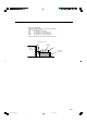
Caution: Proper Ventilation To avoid risk of electric shock and fire and to protect from damage. Locate the apparatus as follows: Front: No obstructions open spacing. Sides: No obstructions in 10 cm from the sides. Back: No obstructions in 15 cm from the back. Bottom: No obstructions, place on the level surface. In addition, maintain the best possible air circulation as illustrated. Spacing 15 cm or more RX-F10S Front Wall or obstructions Stand height 15 cm or more Floor G-2 safety_RX-F10[B]_f.
SAFETY INSTRUCTIONS “SOME DOS AND DON’TS ON THE SAFE USE OF EQUIPMENT” This equipment has been designed and manufactured to meet international safety standards but, like any electrical equipment, care must be taken if you are to obtain the best results and safety is to be assured. Do read the operating instructions before you attempt to use the equipment.
Table of Contents Parts identification ................................................ 2 Getting started ...................................................... 4 Before Installation .................................................................. 4 Checking the supplied accessories ....................................... 4 Putting batteries in the remote control ................................... 4 Connecting the FM and AM (MW) antennas ......................... 5 Connecting the speakers ...............
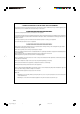
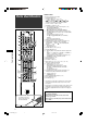
Remote control Parts identification 1 2 3 r t 4 y u 5 Parts identification 6 7 8 9 i p q w o ; a e s See pages in parentheses for details.
See pages in parentheses for details.
Getting started Putting batteries in the remote control Before using the remote control, put two supplied batteries first. 1 Before Installation General precautions • Be sure your hands are dry. • Turn the power off to all components. • Read the manuals supplied with the components you are going to connect. Locations • Install the receiver in a location that is level and protected from moisture and dust. • The temperature around the receiver must be between –5˚C and 35˚C.
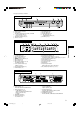
Connecting the FM and AM (MW) antennas AM (MW) loop antenna (supplied) If FM reception is poor, connect an outdoor FM antenna (not supplied). Snap the tabs on the loop into the slots of the base to assemble the AM (MW) loop antenna. FM antenna (supplied) FM 75 COAXIAL AM LOOP AM EXT If AM (MW) reception is poor, connect an outdoor single vinylcovered wire (not supplied). Getting started ANTENNA AM (MW) antenna connection Connect the AM (MW) loop antenna supplied to the AM LOOP terminals.
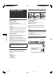
Connecting the speakers Speaker Layout Diagram C L R LS Center speaker (C) SW CAUTION: SPEAKER IMPEDANCE 6 ~ 16 RS SB FRONT RIGHT LEFT CENTER SURROUND RIGHT LEFT SURROUND SPEAKERS BACK SUBWOOFER OUT Powered subwoofer (SW) Right front speaker (R) Getting started Left front speaker (L) Surround back speaker (SB) Right surround speaker (RS) Left surround speaker (LS) Connecting the speakers Connecting the powered subwoofer Turn off all components before making connections.
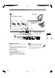
DO NOT use a TV through a VCR or a TV with a built-in VCR; otherwise, the picture may be distorted. Connecting video components SCART connection You can enjoy pictures and sounds from playback components simply by connecting with the SCART cable. • If your video components have digital output terminal, also connect them using the digital terminals explained in “Digital connection” (see page 11). By using these terminals, you can get better sound quality. Turn off all components before making connections.
For TV and video format For T-V LINK This receiver cannot convert the video signals. When the video signal of one video component is different from that of the other (for example, one is S-video, the other is Composite), you may not see the pictures appropriately. In this case, unify the video signals of all the video components, or you need to switch the video signal of TV each time you change the source.
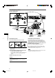
When you connect a DVD player with its analogue discrete output jacks (DVD MULTI IN): This connection is the best connection method for enjoying DVD Audio sounds. When a DVD Audio disc is played back, the original highquality sounds can be reproduced only using this connection. Turn off all components before making connections.
7 Connecting another video component to the VIDEO IN jacks If your video components have S-video (Y/C-separation) and/or component video (Y, PB, PR) terminals, connect them using an S-video cable (not supplied) and/or component video cable (not supplied). By using these jacks, you can get better picture quality in the order: Component video > S-video > Composite video To enjoy the playback from the component connected to these jacks, select “VIDEO” as the source (see page 12).
Digital connection This receiver is equipped with three DIGITAL IN terminals—one digital coaxial terminal and two digital optical terminals. To reproduce the digital sound, use the digital connection in addition to the analogue connection methods described on pages 7 to 10. Digital coaxial cable (supplied: 1 cable) Digital optical cable (not supplied) Connecting the power cord When all the audio/video connections have been made, connect the AC power plug to the wall outlet.
2 Select the source to play Basic operations On the front panel: Turn SOURCE SELECTOR until the source name you want appears on the display. The source lamp corresponding to the selected source lights in red. • As you turn SOURCE SELECTOR, the source changes as follows: 1 2 3 EQ C.TONE VIRTUAL SB AUDIO P. BASS TA NEWS INFO RDS TUNED ST AUTO MUTING SLEEP AUTO MODE PL ATT LPCM L C R HP DOLBY D S .
3 Adjust the volume To increase the volume, turn MASTER VOLUME control clockwise (or press VOLUME + on the remote control). To decrease the volume, turn MASTER VOLUME control counterclockwise (or press VOLUME – on the remote control). • When you adjust the volume, the volume level indication appears on the display for a while. EQ C.TONE VIRTUAL SB AUDIO P. BASS TA NEWS INFO RDS TUNED ST AUTO MUTING SLEEP AUTO MODE PL ATT LPCM L C R HP DOLBY D S .
Activating TV Direct TV Direct enables you to use this receiver as an AV selector while the receiver is turned off. When TV Direct is activated, the pictures and sounds go from the video components such as DVD player to the TV through this receiver. Thus, you can use the video components and the TV as if they were connected directly. • This function takes effect for the following sources—DVR/DVD, VCR, and VIDEO.
Turning off the sounds temporarily From the remote control ONLY: Press MUTING to turn off the sound through all connected speakers and headphones connected. “MUTING” appears on the display and the volume turns off. EQ C.TONE VIRTUAL SB AUDIO P. BASS TA NEWS INFO RDS TUNED ST AUTO MUTING SLEEP AUTO MODE PL ATT LPCM L C R HP DOLBY D S . WFR LFE NEO : 6 MHz DSP 3D DTS AAC LS SB RS AUTO SR kHz 96 / 24 To restore the sound, press MUTING again.
2 Press and hold SMART SURROUND SETUP Basic settings until “SETTING UP” flashes on the display. EQ C.TONE VIRTUAL SB AUDIO P. BASS TA NEWS INFO RDS TUNED ST AUTO MUTING SLEEP AUTO MODE PL ATT LPCM L C R HP DOLBY D S . WFR LFE NEO : 6 MHz DSP 3D DTS AAC LS SB RS AUTO SR kHz 96 / 24 3 Confirm that “SETTING UP” stops flashing, then clap your hands over your head once while “SETTING UP” still remains on the display.
• When the receiver detects the sound as “SILENT” twice in succession. The setting is made. (The distance of the speakers from which sound has not been detected is set to “+9.0m (+30ft).”) The receiver exits from Smart Surround Setup. • When the receiver fails to detect the sound three times. “MANUAL” appears on the display. The receiver exits from Smart Surround Setup. To cancel Smart Surround Setup, press SMART SURROUND SETUP while “SETTING UP” flashes on the display.
Operating procedure Setting the speakers 3, 5 1 2, 4 Setting subwoofer information—SUBWOOFER Each time the receiver turns on, the receiver detects the subwoofer connection and automatically changes the setting of the subwoofer. When you want to change the setting manually, select either one below. On the front panel ONLY: Before you start, remember... There is a time limit in doing the following steps. If the setting is canceled before you finish, start from step 1 again. Ex.
Setting the speaker distance The distance from your listening point to the speakers is one of the important elements to obtain the best possible sound effect from the Surround/DSP modes. By referring to the speaker distance, the receiver automatically sets the delay time of the sound through each speaker so that sounds through all the speakers can reach you at the same time. • If you have used Smart Surround Setup on page 16, this setting is not required.
Activating the EX/ES setting—EX/ES Depending on this setting, available Surround modes for digital multi-channel software vary—EX/ES (6.1-channel) reproduction or 5.1-channel reproduction. Select an appropriate setting for your enjoyment. • For details about relation between EX/ES setting and available Surround mode, see page 34. • To activate the Surround mode, see page 35. EX/ES :AUTO According to the incoming signal, an appropriate Surround mode is applied.
Setting the digital input (DIGITAL IN) terminals—DIGITAL IN1/2/3 When you use the digital input terminals, register what components are connected to which terminals—DIGITAL IN1/2/3 (see page 11) so that the correct source name will appear when you select the digital source. Select one of the following components for each terminal: DVR/DVD For DVD player (or DVD recorder). VIDEO For the component connected to the VIDEO IN jacks on the rear of the receiver. VCR For VCR. TV For TV.
Sound adjustments Operating procedure 3, 5 1 2, 4 On the front panel: Before you start, remember... You can make sound adjustment to your preference after completing basic setting. There is a time limit in doing the following steps. If the setting is canceled before you finish, start from step 1 again. Ex.: When adjusting subwoofer output level. Basic adjustment items Sound adjustments You can adjust the following items. See pages in parentheses for details.
Adjusting speaker output level • • • • • • • Adjusting the sound parameters for the Surround/DSP modes SUBWFR LVL (subwoofer output level), FRONT L LVL (left front speaker output level), FRONT R LVL (right front speaker output level), CENTER LVL (center speaker output level), SURR L LVL (left surround speaker output level), SURR R LVL (right surround speaker output level), S BACK LVL (surround back speaker output level) You can adjust the Surround/DSP sound parameters to your preference.
Adjusting the sound localization of the center channel—CENTER GAIN Selecting the subwoofer sound phase—SBWFR PHASE This setting is available only when Neo:6 Music is in use. • If you have set “CENTER SPK” to “NO” (see page 18), the center gain is not adjustable. • Once you have made an adjustment, it is memorized until you change the setting. • You cannot use the remote control for this setting. You can change the subwoofer sound phase to your preference.
Tuner operations Tuning in to stations manually From the remote control ONLY: 1 Press FM/AM to select the band. The last received station of the selected band is tuned in. • Each time you press the button, the band alternates between FM and AM (MW). EQ C.TONE VIRTUAL SB AUDIO P. BASS TA NEWS INFO RDS TUNED ST AUTO MUTING SLEEP AUTO MODE PL ATT LPCM L C R HP DOLBY D S . WFR LFE NEO : 6 MHz DSP 3D DTS AAC LS SB RS AUTO SR kHz 96 / 24 Tuner operations are mainly done from the remote control.
3 Press the numeric buttons (1 – 10, +10) to On the front panel: select a channel number while the channel number position is flashing. 2 1, 3 • For channel number 5, press 5. • For channel number 15, press +10, then 5. • For channel number 30, press +10, +10, then 10. EQ C.TONE VIRTUAL SB AUDIO P. BASS TA NEWS INFO RDS TUNED ST AUTO MUTING SLEEP AUTO MODE PL ATT LPCM L C R HP DOLBY D S .
Using the Radio Data System (RDS) to receive FM stations Only the buttons on the remote control are used for RDS operations. When operating the receiver using the remote control, set the mode selector to “AUDIO/TV/VCR/STB.” With the receiver, you can receive the following types of RDS signals: PS (Program Service): Shows commonly known station names. PTY (Program Type): Shows types of broadcast programs. RT (Radio Text): Shows text messages the station sends. Enhanced Other Networks: See page 30.
Searching for a program by PTY codes PTY codes One of the advantages of the RDS service is that you can locate a particular kind of program from the preset channels (see pages 25 and 26) by specifying the PTY codes. Alarm ! News To search for a program using the PTY codes TEST Affairs Document Info (Information) There is a time limit in doing the following steps. If the setting is canceled before you finish, start from step 1 again.
Description of the PTY codes: News: News. Social: Affairs: Topical program expanding or enlarging upon the news—debate or analysis. Programs about sociology, history, geography, psychology and society. Religion: Religious programs. Info (Information): Programs the purpose of which is to impart advice in the widest sense. Phone In: Involving members of the public expressing their views either by phone or at a public forum. Sport: Travel: Travel information.
Switching to broadcast program of your choice temporarily Another convenient RDS service is called “Enhanced Other Networks.” This allows the receiver to switch temporarily to a broadcast program of your choice (TA, NEWS, and/or INFO) from a different station except in the following case: • The Enhanced Other Networks mode only works when receiving an FM station with the Enhanced Other Networks code. Before you start, remember... The Enhanced Other Networks function is only applicable to preset FM stations.
Creating realistic sound fields Introducing the Surround modes ■ Dolby Digital* Dolby Digital is a digital signal compression method, developed by Dolby Laboratories, and enables multi-channel encoding and decoding (1ch up to 5.1ch). • When Dolby Digital signal is detected through the digital input, the DOLBY D indicator lights up on the display. Dolby Digital 5.
■ DTS** DTS is another digital signal compression method, developed by Digital Theater Systems, Inc., and enables multi-channel encoding and decoding (1ch up to 6.1ch). • When DTS signal is detected through the digital input, the DTS indicator lights up on the display. DTS Digital Surround DTS Digital Surround (DTS) is another discrete 5.1 channel digital audio format available on CD, LD, and DVD software.
Introducing the DSP modes The sound heard in a concert hall, club, etc. consists of direct sound and indirect sound—early reflections and reflections from behind. Direct sounds reach the listener directly without any reflection. On the other hand, indirect sounds are delayed by the distances of the ceiling and walls. These direct sounds and indirect sounds are the most important elements of the acoustic surround effects.
Using the Surround/DSP modes Available Surround/DSP modes vary depending on the speaker settings and the incoming signals. See the table below. • The numbers inside the parentheses following the incoming signal type indicate the number of the front channels and that of the surround channels. For example, (3/2) indicates that the signals are encoded with three front signals (left/right/center) and two (stereo) surround signals. • For EX/ES setting, see page 20.
Activating the Surround/DSP modes On the front panel: 2 Available Surround/DSP modes vary depending on the speaker settings and the incoming signals. For details, see page 34. Activating one of the Surround/DSP modes for a source automatically recalls the memorized settings and adjustments. • To adjust the speaker output level, see page 23. • To adjust the effect level for the DSP mode (except All Channel Stereo mode), see page 23.
Operating other JVC products 7 VCR Set the mode selector to “AUDIO/TV/VCR/STB.” You can use the supplied remote control to operate not only this receiver but also other JVC products. • Refer also to the manuals supplied with the other products. – Some JVC VCRs can accept two types of the control signals—remote codes “A” and “B.” This remote control can operate a VCR whose remote control code is set to “A.
7 DVD recorder or DVD player For various playback: (one touch replay): Move the playback position back 10 seconds before the current position. To operate the DVD player, set the mode selector to “DVD.” Return to the main menu during menu operation. CANCEL: Cancel the programmed track, etc. For DVD recorder operations: CHANNEL +/–: Change the channel numbers. DVD/HDD: (skip): After setting the mode selector, you can perform the following operations on the DVD recorder or DVD player.
Manufacturers’ codes for TV Operating other manufacturers’ products Manufacturer By changing the transmittable signals, you can use the supplied remote control to operate other manufacturers’ products. • Refer also to the manuals supplied with the other products. • To operate those components with the remote control, first you need to set the manufacturers’ codes each for the STB, VCR, and TV. • After replacing batteries of the remote control, set the manufacturers’ codes again.
❏ Changing the transmittable signals for operating a VCR Set the mode selector to “AUDIO/TV/VCR/STB.” 1 Press and hold VCR . 2 Press VCR. 3 Enter the manufacturer’s code using buttons 1 – 9, and 0. See “Manufacturers’ codes for VCR” on the right. 4 Release VCR . Now, you can perform the following operation on the VCR. VCR : Turn on or off the VCR. After pressing VCR, you can perform the following operations on the VCR. CHANNEL +/–: Change the channel numbers on the VCR.
❏ Changing the transmittable signals for operating an STB Set the mode selector to “AUDIO/TV/VCR/STB.” 1 Press and hold STB . 2 Press STB CONT. 3 Enter the manufacturer’s code using buttons 1 – 9, and 0. See “Manufacturers’ codes for STB” on the right. 4 Release STB . Now, you can perform the following operation on the STB. STB : Turn on or off the STB. After pressing STB CONT, you can perform the following operations on the STB. CHANNEL +/–: Change the channel numbers on the STB.
Troubleshooting Use this chart to help you solve daily operational problems. If there are any problems you cannot solve, contact your JVC’s service center. The power cord is not plugged in. Plug the power cord into an AC outlet. The receiver turns off (enters standby mode). Speakers are overloaded because of high volume. 1. Stop the playback source. 2. Turn on the receiver again, then turn the volume down. Speakers are overloaded because of a short circuit at the speaker terminals.
Video Specifications Video Input Sensitivity/Impedance: Composite video: DVR/DVD, VCR, TV, VIDEO: 1 V(p-p)/75 Ω S-video: DVR/DVD, VCR, VIDEO: Y (luminance): 1 V(p-p)/75 Ω C (chrominance, burst): 0.3 V(p-p)/75 Ω RGB: DVR/DVD, VCR: 0.7 V(p-p)/75 Ω Component: DVR/DVD, VIDEO: Y (luminance): 1 V(p-p)/75 Ω 0.7 V(p-p)/75 Ω PB, PR: Designs and specifications are subject to change without notice.
RX-F10S HOME CINEMA CONTROL CENTER VICTOR COMPANY OF JAPAN, LIMITED EN © 2004 VICTOR COMPANY OF JAPAN, LIMITED cover_RX-f10[B]_f.p65 2 0204MWMMDWJEIN 04.2.