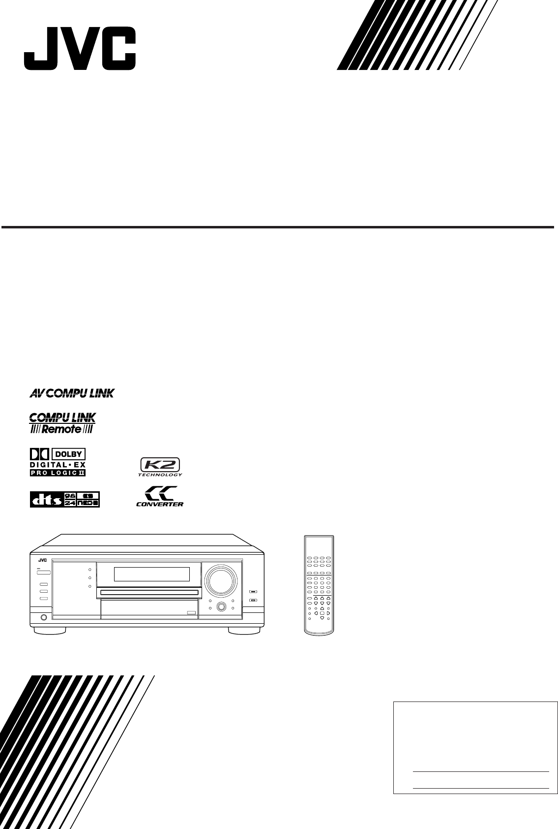
AUDIO/VIDEO CONTROL RECEIVER RX-8030VBK RX-7030VBK/RX-7032VSL (For RX-8030VBK) (For RX-8030VBK) A/V CONTROL RECEIVER 1 2 4 5 7/P 8 9 0 +10 3 MENU 6 ENTER 10/0 CONTROL INSTRUCTIONS For Customer Use: Enter below the Model No. and Serial No. which are located either on the rear, bottom or side of the cabinet. Retain this information for future reference. Model No. Serial No. LVT1007-001A[J] COVER_8030&7030[J]f.pm6 1 03.2.
Warnings, Cautions and Others/ Mises en garde, précautions et indications diverses CAUTION RISK OF ELECTRIC SHOCK DO NOT OPEN CAUTION: TO REDUCE THE RISK OF ELECTRIC SHOCK. DO NOT REMOVE COVER (OR BACK) NO USER SERVICEABLE PARTS INSIDE. REFER SERVICING TO QUALIFIED SERVICE PERSONNEL.
Table of Contents Introduction ................................................ 2 Basic Settings ........................................... 25 Features ...................................................................................... 2 Precautions ................................................................................. 2 Setting the Speakers Configuration .......................................... 25 Basic Setting Items ...................................................................
Introduction We would like to thank you for purchasing one of our JVC products. Before operating this unit, read this manual carefully and thoroughly to obtain the best possible performance from your unit, and retain this manual for future reference.
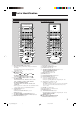
Parts Identification Remote Control RX-8030VBK RX-7030VBK/RX-7032VSL A/V CONTROL RECEIVER A 1 2 3 CATV/DBS VCR 1 TV AUDIO DVD MULTI DVD CD FM/AM VCR 1 VCR 2 CDR TAPE/MD TV/DBS VIDEO 3 CATV/DBS VCR DVD MULTI DVD TV/DBS VCR SURROUND DSP SURR/DSP ANALOG OFF EX/ES DIRECT e r 4 BASSBOOST 1 2 DSP SURROUND CC CONVERTER TEST 7 8 9 4 5 6 MIDNIGHT MODE SOUND CATV/DBS CONTROL TV/VIDEO 8 7/P ∗DIGITALEQ ∗SURR BACK BASSBOOST CD DISC TEST +10 100+ + + ∗ CH/ LEVEL T
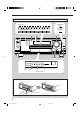
Front Panel 6 8 RX-8030VBK RX-8030VBK CC CONVERTER DVD MULTI VCR 1 DVD VCR 2 VIDEO TV SOUND /DBS PHONO CD CDR TAPE/MD FM AM RX-7030VBK RX-7032VSL RX-7030VBK/RX-7032VSL BASS BOOST DVD MULTI DVD 2 1 VCR TV SOUND/DBS 3 CD 4 TAPE/CDR FM AM 5 7 MASTER VOLUME SURROUND STANDBY DSP STANDBY/ON SPEAKERS ON/OFF SURROUND/ DSP OFF 1 2 DVD MULTI DVD VCR TV SOUND/DBS CD TAPE/CDR FM AM SUBWOOFER OUT ON/OFF SETTING ADJUST ANALOG DIRECT MULTI JOG QUICK SPEAKER SETUP EXIT
Front Panel 1 STANDBY/ON button and STANDBY lamp (17) 2 • SPEAKERS ON/OFF 1 button (19) • SPEAKERS ON/OFF 2 button (19) 3 • SURROUND button (37) • DSP button (39) • SURROUND/DSP OFF button (37, 39) 4 Remote sensor 5 Display window (17) 6 • For RX-8030VBK: Source selection buttons and lamps (17, 18, 19, 21, 23, 24, 37, 40) DVD MULTI, DVD, VCR 1, VCR 2, VIDEO, TV SOUND/DBS, PHONO, CD, CDR, TAPE/MD, FM, AM (The lamp above the button for selected source lights up.
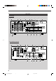
Rear Panel RX-8030VBK 1 3 2 SUBWOOFER CENTER RIGHT VIDEO LEFT S-VIDEO SURR BACK DVD IN DVD IN DIGITAL 2 (CD) DIGITAL 3 (TV) OUT (REC) OUT (REC) AV COMPULINK- IN MONITOR OUT CAUTION : SPEAKER IMPEDANCE 8 PB PR 16 CAUTION : SPEAKER IMPEDANCE CDR See Instruction Manual For Connection – MONITOR OUT – CD IN DIGITAL OUT PHONO IN RIGHT 16 32 OR SINGLE USE IN (PLAY) PCM/ DOLBY DIGITAL / DTS 2 : 8 1 AND 2 : 16 + 1 + COAXIAL VCR 2 IN (PLAY) LEFT RIGHT LEFT SURROUND BACK SP
Rear Panel RX-8030VBK RX-7030VBK/RX-7032VSL 1 DIGITAL IN terminals (16) • Coaxial: DIGITAL 1 (DVD) • Optical: DIGITAL 2 (CD), DIGITAL 3 (TV), DIGITAL 4 (CDR) 2 AUDIO input/output jacks (11 – 15) • Input: DVD IN—FRONT, CENTER, SUBWOOFER, SURR (REAR), TV SOUND/DBS IN, VCR 1 IN (PLAY), VCR 2 IN (PLAY), CD IN, TAPE/MD IN (PLAY), CDR IN (PLAY), PHONO IN • Output: VCR 1 OUT (REC), VCR 2 OUT (REC), TAPE/MD OUT (REC), CDR OUT (REC) 3 S-VIDEO and composite VIDEO input/output jacks (14, 15) • Input: DVD IN, TV SOUN
Getting Started This section explains how to connect audio/video components and speakers to the receiver, and how to connect the power supply. If the remote control cannot transmit signals or operate the receiver correctly, replace the batteries. Use two R6P(SUM-3)/AA(15F) type dry-cell batteries. Before Installation General Precautions • Be sure your hands are dry. • Turn the power off to all components. • Read the manuals supplied with the components you are going to connect.
AM Antenna Connections Basic connecting procedure Turn the loop until you have the best reception. 1 Twist and remove the insulation at the end of each speaker signal cable (not supplied). 2 Open the speaker terminal. ANTENNA AM EXT + AM Loop Antenna (supplied) AM LOOP – RIG HT T LE Snap the tabs on the loop into the slots of the base to assemble the AM loop. FM 75 LEF RIG RX-7030VBK/RX-7032VSL (For FRONT SPEAKERS 2 terminals) 3 Insert the speaker signal cable.
• Rear terminals of RX-8030VBK are used for explanation. Surround back speakers* Right / Left CAUTION : SPEAKER IMPEDANCE 8 Front speakers 2 Right / Left Front speakers 1 Right / Left Center speaker 16 CAUTION : SPEAKER IMPEDANCE + 1 + 2 : 8 16 1 AND 2 : 16 32 OR SINGLE USE See Instruction Manual For Connection – – LEFT RIGHT SURROUND BACK SPEAKERS * When using only one surround back speaker, connect the ª cord to the RIGHT ª terminal and the · cord to the LEFT · terminal.
Enhancing your audio system —Only for RX-8030VBK RX-8030V ONLY You can use this receiver as the pre-amplifier (control amplifier) when you connect power amplifiers to the PREOUT jacks on the rear using cables with RCA pin plugs (not supplied). • Connect the white plug to the audio left jack, and the red plug to the audio right jack. Connecting Audio/Video Components When connecting individual components, refer also to the manuals supplied with them.
CD recorder CD player To listen to the sound after connection, press CD. To listen to the sound after connection, press CDR (for RX-8030VBK) or TAPE/CDR (for RX-7030VBK/RX-7032VSL). For RX-8030VBK RX-8030VBK RX-7030VBK/RX-7032VSL CD player RX-8030VBK R L CD IN CD recorder To audio input To audio output Cassette deck To audio output R To listen to the sound after connection, press TAPE/MD (for RX8030VBK) or TAPE/CDR (for RX-7030VBK/RX-7032VSL).
Video component connections MD recorder To listen to the sound after connection, press TAPE/MD (for RX8030VBK) or TAPE/CDR (for RX-7030VBK/RX-7032VSL). For RX-8030VBK You can connect either an MD recorder or a cassette deck to the TAPE/MD jacks. When connecting a cassette deck, see page 12. If your video components have an AV COMPULINK jack See also page 42 for detailed information about the connection and the AV COMPU LINK remote control system.
VCR(s) TV and/or DBS tuner To listen to the sound after connection, press VCR 1 or VCR 2 (for RX-8030VBK) or VCR (for RX-7030VBK/RX-7032VSL). For RX-8030VBK You can connect two VCRs—one to the VCR 1 jacks and the other to the VCR 2 jacks. • If your VCR has an AV COMPU LINK jack, connect it to the VCR 1 jack so that you can use the AV COMPU LINK remote control system.
DVD player • When you connect a DVD player with stereo output jacks: To listen to the sound after connection, press DVD. • When you connect a DVD player with its analog discrete output (5.1-channel reproduction) jacks: To listen to the sound after connection, press DVD MULTI.
Digital Connections Digital output terminal This receiver is equipped with four DIGITAL IN terminals—one digital coaxial terminal and three digital optical terminals—and one DIGITAL OUT (optical) terminal on the rear. • For RX-8030VBK: Another digital optical input terminal is located on the front panel (see page 13). You can connect any digital components which have an optical digital input terminal.
Basic Operations The following operations are commonly used when you play any sound sources. Operations hereafter will be explained using the buttons on the front panel. You can also use the buttons on the remote control for the same functions if they have the same and similar names/marks. Selecting the Source to Play Daily Operational Procedure 1 3 4 2 Press one of the source selection buttons. • The selected source name and the previously selected Surround/ DSP mode also appear on the display.
Speaker and signal indicators on the display By checking the following indicators, you can easily confirm which speakers you are activating and which signals are coming into this receiver. Speaker indicators L C Signal indicators R L C SUBWFR LS R LFE RS LS SB S RS Selecting different sources for picture and sound While watching pictures from a video source, you can listen to sound of an audio source.
Selecting the Front Speakers Remote NOT When you have connected two pairs of the front speakers, you can select which to use. To use the speakers connected to the FRONT SPEAKERS 1 terminals, press SPEAKERS ON/OFF 1 so that the SPEAKERS 1 indicator lights up on the display. Make sure that the SPEAKERS 2 indicator is not lit on the display. To use the speakers connected to the FRONT SPEAKERS 2 terminals, press SPEAKERS ON/OFF 2 so that SPEAKERS 2 indicator lights up on the display.
2. Press INPUT DIGITAL (or ANALOG/DIGITAL INPUT on the remote control) to select “DGTL AUTO.” Setting the Dynamic Range You can enjoy a powerful sound at night using the Midnight Mode. The DIGITAL AUTO indicator lights up on the display. DIGITAL AUTO L C R SUBWFR LFE LS SPEAKERS 1 DIGITAL RS VOLUME • When selecting “DGTL AUTO,” the following indicators indicate the digital signal format of the incoming signal. LINEAR PCM DIGITAL : Lights up when Linear PCM signals come in.
Turning Analog Direct On and Off Remote NOT Changing the Source Name You can enjoy the sound closer to the original source by overriding the sound adjustments such as speaker output level adjustments (see page 32), Digital Equalization (see page 32), Surround and DSP modes (see pages 34 to 39), Bass Boost (see page 22) and Midnight Mode (see page 20). You can only adjust the volume level while Analog Direct is in use. • Once you have made adjustment, it is memorized for each analog source.
The following basic operations are possible only using the remote control. Using the Sleep Timer Using the Sleep Timer, you can fall asleep while listening to music. When the shut-off time comes, the receiver turns off automatically. BASS BOOST Reinforcing the Bass 1 2 3 4 5 6 7/P 8 9 10/0 0 +10 Press SLEEP repeatedly.
Receiving Radio Broadcasts You can browse through all the stations or use the preset function to go immediately to a particular station. Tuning in to Stations Manually Using Preset Tuning 1. Press FM or AM to select the band. The last received station of the selected band is tuned in. TUNED STEREO ANALOG L R Once a station is assigned to a channel number, the station can be quickly tuned in. You can preset up to 30 FM and 15 AM stations.
To tune in a preset station Selecting the FM Reception Mode On the front panel: 1. Press FM or AM to select the band. The last received station of the selected band is tuned in. 2. Press FM/AM PRESET 5 or ∞ until you find the channel you want. • Pressing FM/AM PRESET 5 increases the number. • Pressing FM/AM PRESET ∞ decreases the number. When an FM stereo broadcast is hard to receive or noisy, you can change the FM reception mode while receiving an FM broadcast.
Basic Settings Some of the following settings are required after connecting and positioning your speakers while others will make operations easier. You can use QUICK SPEAKER SETUP to easily set up your speaker configuration. Setting the Speakers Configuration Remote NOT Quick Speaker Setup helps you to easily and quickly register the speaker size and speaker distance according to your listening room to create the best possible surround effect. • You can also register each speaker’s information manually.
Speakers (channels) number and the size You can find how each of the speaker size is defined according to the number of connected speakers (speaker channel (CH) number) you select. In the following tables, “L” stands for “left front speaker,” “R” for “right front speaker,” “C” for “center speaker,” “LS” for “left surround speaker,” “RS” for “right surround speaker,” “SB” for “surround back speaker,” and “SUBWFR” for “subwoofer.” • Subwoofer is counted as 0.1 channel.
Basic Procedure : shows the initial setting in the following tables. Setting the Speakers Before you start, remember... There is a time limit in doing the following steps. If the setting is canceled before you finish, start from step 1 again. To obtain the best possible surround effect from the Surround and DSP modes, register the setting about the speaker arrangement after all connections are completed. • If you have used Quick Speaker Setup on page 25, this setting is not required.
Setting the Speaker Distance Setting the Bass Sounds The distance from your listening point to the speakers is another important element to obtain the best possible sound of the Surround and DSP modes. Set the distance from your listening point to the speakers. By referring to the speaker distance setting, this unit automatically sets the delay time of the sound through each speaker so that sounds through all the speakers can reach you at the same time.
7 Low frequency effect attenuator—LFE ATTENUATE If the bass sound is distorted while playing back software encoded with Dolby Digital or DTS, set the LFE level to eliminate distortion. When you use the digital input terminals, register which components you have connected to the digital input terminals. 7 Digital coaxial terminal—DGTL IN COAX Select one of the following: 0dB: Set the component connected to the digital coaxial terminal (DIGITAL IN 1). Normally select this.
For RX-7030VBK/RX-7032VSL: Memorizing the Volume Level for Each Source As you set the components connected to the digital coaxial terminal (DIGITAL IN 1), the optical terminals (DIGITAL IN 2 – 4) will be automatically fixed to connect the components listed below. This unit memorizes some settings separately for each source. In addition, you can store the volume level for each source with the other memorized settings—One Touch Operation.
Adjusting Sound You can make sound adjustment to your preference after completing basic setting. Basic Setting Items Basic Procedure On the following pages, you can adjust the items listed below: • You can adjust only the items applicable to the current sound mode. • If Analog Direct is in use, you cannot make any sound adjustments. Items To do See page DIGITAL EQ Adjust equalizer pattern. 32 SUBWFR LVL Adjust the subwoofer output level.
Adjusting the Equalization Patterns Adjusting the Speaker Output Levels You can adjust the equalization patterns to your preference. • Once you have made adjustment, it is memorized for each source. You can adjust the speaker output levels. The test tone comes out of each speaker except subwoofer to check the output level balance when using the Surround mode. • Once you have made an adjustment, it is memorized for each source.
You can also use the remote control for adjusting the speaker output level. When using the remote control, you can make an adjustment while listening to test tone. 1 2 3 4 5 6 7/P 8 9 10/0 0 +10 Adjusting the Sound Parameters for the Surround and DSP Modes You can adjust the Surround and DSP sound parameters to your preference. • When center speaker is set to “NONE,” CTR TONE, CNTR WIDTH, and CNTR GAIN are not available.
Using the Surround Modes This unit activates a variety of Surround modes automatically. The basic settings and adjustments stored (see pages 25 to 33) are applied. Reproducing Theater Ambience Introducing the Surround Modes In a movie theater, many speakers are located on the walls to reproduce impressive multi-surround sounds, reaching you from all directions. With these many speakers, sound localization and sound movement can be expressed.
Dolby Pro Logic II DTS 96/24 Dolby Pro Logic II is a multi-channel playback format to convert 2channel software into 5-channel (plus subwoofer). The matrix-based conversion method used for Dolby Pro Logic II makes no limitation for the cutoff frequency of the surround treble and enables stereo surround sound. • This receiver provides two types of Dolby Pro Logic II modes— Pro Logic II Movie (PLII MOVIE) and Pro Logic II Music (PLII MUSIC).
Surround Modes Applicable to the Various Software Available Surround modes vary depending on the speaker settings and the incoming signals. The table below shows the relation of the Surround modes and the incoming signals (with the surround back speakers and EX/ES setting). • The numbers inside the parentheses following the incoming signal type indicate the number of the front channels and that of the surround channels.
Activating the Surround Modes Activating the Surround Modes Available Surround modes vary depending on the speaker settings and the incoming signals. (See page 36.) Activating one of the Surround modes for a source automatically recalls the memorized settings and adjustments (see pages 25 to 33.) You can also use the buttons on the remote control for the same functions. Activating the EX/ES setting For multi-channel digital software, you can activate the EX/ES (7.1channel) reproduction mode.
Using the DSP Modes This unit activates a variety of DSP modes automatically. The basic settings and adjustments stored (see pages 25 to 33) are applied automatically. Reproducing the Sound Field The sound heard in a concert hall, club, etc. consists of direct sound and indirect sound—early reflections and reflections from behind. Direct sounds reach the listener directly without any reflection. On the other hand, indirect sounds are delayed by the distances of the ceiling and walls.
ALL Channel Stereo mode This mode can reproduce a larger stereo sound field using all the connected (and activated) speakers. This mode cannot be used without activating the surround speakers. • If the front speakers are deactivated, “All Channel Stereo” cannot be selected. Activating the DSP Modes Activating one of the DSP modes for a source automatically recalls the memorized settings and adjustments (see pages 25 to 33.) You can also use the buttons on the remote control for the same functions. 1.
Using the DVD MULTI Playback Mode This receiver provides the DVD MULTI playback mode for reproducing the analog discrete output mode of the DVD player. Activating the DVD MULTI Playback Mode Connection diagram COMPONENT VIDEO DVD IN RX-8030VBK RX-7030VBK/RX-7032VSL VIDEO AUDIO SUBWOOFER CENTER RIGHT VIDEO LEFT S-VIDEO DVD IN DVD IN 1. Press DVD MULTI so that “DVD MULTI” appears on the display. The MULTI indicator also lights up.
COMPU LINK Remote Control System The COMPU LINK remote control system allows you to operate JVC’s audio components through the remote sensor on the receiver. To use this remote control system, you need to connect JVC’s audio components through the COMPU LINK (SYNCHRO) jacks (see below) in addition to the connections using cables with RCA pin plugs (see pages 12 and 13). • Make sure that the AC power cords of these components are unplugged before connection.
AV COMPU LINK Remote Control System The AV COMPU LINK remote control system allows you to operate JVC’s video components (TV, VCR, and DVD player) through the receiver. This receiver is equipped with the AV COMPU LINK-III, which adds a function to the previous version in order to operate JVC’s video components through the video components terminals. To use this remote control system, connect the video components you want to operate, following the diagrams below and the procedure on the next page.
1. If you have already plugged your VCR , DVD player, TV and this receiver into the AC outlets, unplug their AC power cords first. 2. Connect your VCR, DVD player, TV and this receiver, using the cables with the monaural miniplugs (not supplied). • See “CONNECTIONS 1” on the previous page. 3. Connect the audio input/output jacks on VCR, DVD player, TV and this receiver using the cables with RCA pin plugs. • See pages 14 and 15. 4.
Operating JVC’s Audio/Video Components You can operate JVC’s audio and video components with this receiver’s remote control, since control signals for JVC’s components are preset in the remote control.
CD changer CD recorder For RX-8030VBK: After selecting “CDDSC” by pressing CONTROL repeatedly, you can perform the following operations on a CD changer: For RX-8030VBK: After pressing CDR (or selecting “CDR” by pressing CONTROL repeatedly), you can perform the following operations on a CD recorder: For RX-7030VBK/RX-7032VSL: After pressing CD DISC, you can perform the following operations on a CD changer: For RX-7030VBK/RX-7032VSL: After pressing TAPE/CDR (or TAPE/CDR CONTROL), you can perform the foll
VCR Operating Video Components You can always perform the following operations: IMPORTANT: To operate JVC’s video components using the supplied remote control: • You need to connect JVC’s video components through the AV COMPU LINK jacks (see page 42) in addition to the connections using cables with RCA pin plugs (see pages 14 and 15). • Some JVC’s VCRs can accept two types of the control signals— remote code “A” and “B.
Operating Other Manufacturers’ Video Equipment This remote control supplied with the receiver can transmit control signals for other manufacturers’ TVs, CATV converters, DBS tuners, VCRs and DVD players. When operating the other manufacturers’ components, refer also to the manuals supplied with them. • After replacing batteries for the remote control, you need to set the manufactures’ codes again. . 3 Enter a manufacturer’s code using buttons 1 – 9, and 0.
To change the transmittable signals for operating another manufacturer’s VCR To change the transmittable signals for operating another manufacturer’s DVD player 1. Press and hold VCR 1 (for RX-8030VBK) or (for RX-7030VBK/RX-7032VSL). VCR 2. Press VCR 1 (for RX-8030VBK) or VCR (for RX7030VBK/RX-7032VSL). 1. Press and hold AUDIO For RX-8030VBK: “CALL” appears on the display window of the remote control. 3. Enter manufacturer’s code using buttons 1 – 9, and 0. See the list on page 49 to find the code. 4.
For TV Manufacturer JVC Akai Blaupunkt Fisher Grundig Hitachi Irradio ITT/NOKIA Loewe Magnavox Mets Mitsubishi Mivar Nordmende Okano Panasonic Philips Codes For VCR Manufacturer 00*, 02, 13, 14, 47, 74 01, 02 03, 04 01, 05 03, 06, 07 08, 09, 10, 49 02 11, 12 06, 15, 16 08, 17, 49 50, 51, 52, 53 08, 18, 19, 20 21 22, 23 15 24, 25, 26, 27 76 15, 17, 28, 75 Quelle RCA/ Proscan SABA Samsung Sanyo Schneider Sharp Sony Telefunken Thomson Toshiba Zenith Codes 52, 53, 54, 55, 56, 57, 58, 59, 60, 61, 62, 63,
Troubleshooting Use this chart to help you solve daily operational problems. If there is any problem you cannot solve, contact your JVC’s service center. PROBLEM SOLUTION POSSIBLE CAUSE The display does not light up. The power cord is not plugged in. Plug the power cord into an AC outlet. No sound from speakers. Speaker signal cables are not connected. Check speaker wiring and reconnect if necessary. (See pages 9 to 11.) The SPEAKERS ON/OFF 1 and SPEAKERS ON/OFF 2 buttons are not set correctly.
Specifications RX-8030VBK Amplifier Output Power At Stereo operation Front ch: 130 W per channel, min. RMS, driven into 8 Ω, 20 Hz to 20 kHz, with no more than 0.08% total harmonic distortion. At Surround operation: Front ch: 130 W per channel, min. RMS, driven into 8 Ω at 1 kHz, with no more than 0.8% total harmonic distortion. Center ch: 130 W, min. RMS, driven into 8 Ω at 1 kHz, with no more than 0.8% total harmonic distortion. Surround ch: 130 W per channel, min.
RX-7030VBK/RX-7032VSL Amplifier Output Power At Stereo operation Front ch: 110 W per channel, min. RMS, driven into 8 Ω, 20 Hz to 20 kHz, with no more than 0.08% total harmonic distortion. At Surround operation: Front ch: 110 W per channel, min. RMS, driven into 8 Ω at 1 kHz, with no more than 0.8% total harmonic distortion. Center ch: 110 W, min. RMS, driven into 8 Ω at 1 kHz, with no more than 0.8% total harmonic distortion. Surround ch: 110 W per channel, min.
LIMITED WARRANTY AUDIO-2 JVC COMPANY OF AMERICA warrants this product and all parts thereof, except as set forth below ONLY TO THE ORIGINAL PURCHASER AT RETAIL to be FREE FROM DEFECTIVE MATERIALS AND WORKMANSHIP from the date of original retail purchase for the period as shown below. ("The Warranty Period") PARTS 2 LABOR YRS 2 YRS THIS LIMITED WARRANTY IS VALID ONLY IN THE FIFTY (50) UNITED STATES, THE DISTRICT OF COLUMBIA AND IN COMMONWEALTH OF PUERTO RICO.
Authorized Service Centers ® QUALITY SERVICE HOW TO LOCATE YOUR JVC SERVICE CENTER TOLL FREE: 1 (800) 537-5722 http://www.jvc.com Dear Customer, In order to receive the most satisfaction from your purchase,please read the instruction booklet before operating the unit.In the event that repairs are necessary, please call 1 (800)537-5722 for your nearest authorized servicer or visit our website at www.JVC.com Remember to retain your Bill of Sale for Warranty Service.
RX-8030VBK RX-7030VBK/RX-7032VSL AUDIO/VIDEO CONTROL RECEIVER VICTOR COMPANY OF JAPAN, LIMITED EN © 2003 VICTOR COMPANY OF JAPAN, LIMITED COVER_8030&7030[J]10.pm6 2 0203NHMMDWJEIN 03.2.
English Français AUDIO/VIDEO CONTROL RECEIVER AMPLI/TUNER DE COMMANDE AUDIO/VIDEO RX-8030VBK RX-7030VBK (For RX-8030VBK) (For RX-8030VBK) A/V CONTROL RECEIVER 1 2 4 5 7/P 8 9 0 +10 3 MENU 6 ENTER 10/0 CONTROL INSTRUCTIONS MANUEL D’INSTRUCTIONS For Customer Use: Enter below the Model No. and Serial No. which are located either on the rear, bottom or side of the cabinet. Retain this information for future reference. Model No. Serial No. LVT1007-002A[C] COVER_8030&7030[C]7.pm6 1 03.2.
Warnings, Cautions and Others/ Mises en garde, précautions et indications diverses CAUTION RISK OF ELECTRIC SHOCK DO NOT OPEN CAUTION: TO REDUCE THE RISK OF ELECTRIC SHOCK. DO NOT REMOVE COVER (OR BACK) NO USER SERVICEABLE PARTS INSIDE. REFER SERVICING TO QUALIFIED SERVICE PERSONNEL.
For U.S.A This equipment has been tested and found to comply with the limits for a Class B digital device, pursuant to part 15 of the FCC Rules. These limits are designed to provide reasonable protection against harmful interference in a residential installation. This equipment generates, uses and can radiate radio frequency energy and, if not installed and used in accordance with the instructions, may cause harmful interference to radio communications.
Caution: Proper Ventilation To avoid risk of electric shock and fire and to protect from damage. Locate the apparatus as follows: Front: No obstructions open spacing. Sides: No obstructions in 10 cm from the sides. Top: No obstructions in 10 cm from the top. Back: No obstructions in 15 cm from the back Bottom: No obstructions, place on the level surface. In addition, maintain the best possible air circulation as illustrated.
Introduction ................................................ 2 Basic Settings ........................................... 25 Features ...................................................................................... 2 Precautions ................................................................................. 2 Setting the Speakers Configuration .......................................... 25 Basic Setting Items ................................................................... 26 Basic Procedure .
English Introduction We would like to thank you for purchasing one of our JVC products. Before operating this unit, read this manual carefully and thoroughly to obtain the best possible performance from your unit, and retain this manual for future reference.
English Parts Identification Remote Control RX-8030VBK RX-7030VBK A/V CONTROL RECEIVER 2 3 CATV/DBS VCR 1 TV AUDIO DVD MULTI DVD CD FM/AM VCR 1 VCR 2 CDR TAPE/MD TV/DBS VIDEO SURROUND DSP 2 3 SURR/DSP ANALOG OFF EX/ES DIRECT e r 4 BASSBOOST 1 2 CC CONVERTER TEST 7 8 9 4 5 6 MIDNIGHT MODE SOUND CATV/DBS CONTROL TV/VIDEO 8 7/P ∗DIGITALEQ ∗SURR BACK RETURN FM MODE 100+ + ∗ CH/ LEVEL TV VOL − − REC PAUSE SLEEP + VOLUME − MUTING /REW 5 AUDIO CD FM/AM TV/D
English Front Panel 6 8 RX-8030VBK RX-8030VBK CC CONVERTER DVD MULTI VCR 1 DVD VCR 2 VIDEO TV SOUND /DBS PHONO CD CDR TAPE/MD FM AM RX-7030VBK RX-7030VBK DVD MULTI 2 1 BASS BOOST DVD VCR 3 TV SOUND/DBS CD 4 TAPE/CDR FM AM 5 7 MASTER VOLUME SURROUND STANDBY DSP STANDBY/ON SPEAKERS ON/OFF SURROUND/ DSP OFF 1 2 SUBWOOFER OUT ON/OFF SETTING EX / ES FM/AM TUNING INPUT ANALOG ADJUST ANALOG DIRECT MULTI JOG MIDNIGHT MODE QUICK SPEAKER SETUP FM/AM PRESET FM MODE MEMOR
English Front Panel 1 STANDBY/ON button and STANDBY lamp (17) 2 • SPEAKERS ON/OFF 1 button (19) • SPEAKERS ON/OFF 2 button (19) 3 • SURROUND button (37) • DSP button (39) • SURROUND/DSP OFF button (37, 39) 4 Remote sensor 5 Display window (17) 6 • For RX-8030VBK: Source selection buttons and lamps (17, 18, 19, 21, 23, 24, 37, 40) DVD MULTI, DVD, VCR 1, VCR 2, VIDEO, TV SOUND/DBS, PHONO, CD, CDR, TAPE/MD, FM, AM (The lamp above the button for selected source lights up.
English Rear Panel RX-8030VBK 1 3 2 SUBWOOFER CENTER RIGHT VIDEO LEFT S-VIDEO SURR BACK DVD IN DVD IN DIGITAL 2 (CD) DIGITAL 3 (TV) IN (PLAY) OUT (REC) OUT (REC) (SYNCHRO) AV COMPULINK- IN SUBWOOFER MONITOR OUT Y CAUTION : SPEAKER IMPEDANCE 8 PB PR 16 CAUTION : SPEAKER IMPEDANCE CDR – MONITOR OUT RIGHT 16 32 OR See Instruction Manual For Connection CD IN DIGITAL OUT PHONO IN 2 : 8 1 AND 2 : 16 SINGLE USE IN (PLAY) IN (PLAY) + 1 + COAXIAL VCR 2 PCM/ DOLBY DIGITAL /
English Rear Panel RX-8030VBK RX-7030VBK 1 DIGITAL IN terminals (16) • Coaxial: DIGITAL 1 (DVD) • Optical: DIGITAL 2 (CD), DIGITAL 3 (TV), DIGITAL 4 (CDR) 2 AUDIO input/output jacks (11 – 15) • Input: DVD IN—FRONT, CENTER, SUBWOOFER, SURR (REAR), TV SOUND/DBS IN, VCR 1 IN (PLAY), VCR 2 IN (PLAY), CD IN, TAPE/MD IN (PLAY), CDR IN (PLAY), PHONO IN • Output: VCR 1 OUT (REC), VCR 2 OUT (REC), TAPE/MD OUT (REC), CDR OUT (REC) 3 S-VIDEO and composite VIDEO input/output jacks (14, 15) • Input: DVD IN, TV SOUND/
English Getting Started This section explains how to connect audio/video components and speakers to the receiver, and how to connect the power supply. If the remote control cannot transmit signals or operate the receiver correctly, replace the batteries. Use two R6P(SUM-3)/AA(15F) type dry-cell batteries. Before Installation General Precautions • Be sure your hands are dry. • Turn the power off to all components. • Read the manuals supplied with the components you are going to connect.
English AM Antenna Connections Basic connecting procedure Turn the loop until you have the best reception. 1 Twist and remove the insulation at the end of each speaker signal cable (not supplied). 2 Open the speaker terminal. ANTENNA AM EXT + AM Loop Antenna (supplied) AM LOOP – RIG HT T LE Snap the tabs on the loop into the slots of the base to assemble the AM loop. FM 75 LEF RIG RX-7030VBK (For FRONT SPEAKERS 2 terminals) 3 Insert the speaker signal cable.
English • Rear terminals of RX-8030VBK are used for explanation. Surround back speakers* Right / Left CAUTION : SPEAKER IMPEDANCE 8 Front speakers 2 Right / Left Front speakers 1 Right / Left Center speaker 16 CAUTION : SPEAKER IMPEDANCE + 1 + 2 : 8 16 1 AND 2 : 16 32 OR SINGLE USE See Instruction Manual For Connection – – LEFT RIGHT SURROUND BACK SPEAKERS * When using only one surround back speaker, connect the ª cord to the RIGHT ª terminal and the · cord to the LEFT · terminal.
RX-8030V ONLY You can use this receiver as the pre-amplifier (control amplifier) when you connect power amplifiers to the PREOUT jacks on the rear using cables with RCA pin plugs (not supplied). • Connect the white plug to the audio left jack, and the red plug to the audio right jack. English Enhancing your audio system —Only for RX-8030VBK Connecting Audio/Video Components When connecting individual components, refer also to the manuals supplied with them.
English CD recorder CD player To listen to the sound after connection, press CDR (for RX-8030VBK) or TAPE/CDR (for RX-7030VBK). To listen to the sound after connection, press CD. For RX-8030VBK RX-8030VBK/RX-7030VBK CD player RX-8030VBK R L CD IN CD recorder To audio input To audio output Cassette deck To audio output R To listen to the sound after connection, press TAPE/MD (for RX8030VBK) or TAPE/CDR (for RX-7030VBK).
To listen to the sound after connection, press TAPE/MD (for RX8030VBK) or TAPE/CDR (for RX-7030VBK). For RX-8030VBK You can connect either an MD recorder or a cassette deck to the TAPE/MD jacks. When connecting a cassette deck, see page 12. If your video components have an AV COMPULINK jack See also page 42 for detailed information about the connection and the AV COMPU LINK remote control system.
English VCR(s) TV and/or DBS tuner To listen to the sound after connection, press VCR 1 or VCR 2 (for RX-8030VBK) or VCR (for RX-7030VBK). For RX-8030VBK You can connect two VCRs—one to the VCR 1 jacks and the other to the VCR 2 jacks. • If your VCR has an AV COMPU LINK jack, connect it to the VCR 1 jack so that you can use the AV COMPU LINK remote control system.
English DVD player • When you connect a DVD player with stereo output jacks: To listen to the sound after connection, press DVD. • When you connect a DVD player with its analog discrete output (5.1-channel reproduction) jacks: To listen to the sound after connection, press DVD MULTI.
English Digital Connections Digital output terminal This receiver is equipped with four DIGITAL IN terminals—one digital coaxial terminal and three digital optical terminals—and one DIGITAL OUT (optical) terminal on the rear. • For RX-8030VBK: Another digital optical input terminal is located on the front panel (see page 13). You can connect any digital components which have an optical digital input terminal.
English Basic Operations The following operations are commonly used when you play any sound sources. Operations hereafter will be explained using the buttons on the front panel. You can also use the buttons on the remote control for the same functions if they have the same and similar names/marks. Selecting the Source to Play Daily Operational Procedure 1 3 4 2 Press one of the source selection buttons.
English Speaker and signal indicators on the display By checking the following indicators, you can easily confirm which speakers you are activating and which signals are coming into this receiver. Speaker indicators L C Signal indicators R L C SUBWFR LS R LFE RS LS S Selecting different sources for picture and sound While watching pictures from a video source, you can listen to sound of an audio source.
Remote NOT When you have connected two pairs of the front speakers, you can select which to use. To use the speakers connected to the FRONT SPEAKERS 1 terminals, press SPEAKERS ON/OFF 1 so that the SPEAKERS 1 indicator lights up on the display. Make sure that the SPEAKERS 2 indicator is not lit on the display. To use the speakers connected to the FRONT SPEAKERS 2 terminals, press SPEAKERS ON/OFF 2 so that SPEAKERS 2 indicator lights up on the display.
English 2. Press INPUT DIGITAL (or ANALOG/DIGITAL INPUT on the remote control) to select “DGTL AUTO.” Setting the Dynamic Range You can enjoy a powerful sound at night using the Midnight Mode. The DIGITAL AUTO indicator lights up on the display. DIGITAL AUTO L C R SUBWFR LFE LS SPEAKERS 1 DIGITAL RS VOLUME • When selecting “DGTL AUTO,” the following indicators indicate the digital signal format of the incoming signal. LINEAR PCM DIGITAL : Lights up when Linear PCM signals come in.
Remote NOT Changing the Source Name You can enjoy the sound closer to the original source by overriding the sound adjustments such as speaker output level adjustments (see page 32), Digital Equalization (see page 32), Surround and DSP modes (see pages 34 to 39), Bass Boost (see page 22) and Midnight Mode (see page 20). You can only adjust the volume level while Analog Direct is in use. • Once you have made adjustment, it is memorized for each analog source.
English The following basic operations are possible only using the remote control. Using the Sleep Timer Using the Sleep Timer, you can fall asleep while listening to music. When the shut-off time comes, the receiver turns off automatically. BASS BOOST Reinforcing the Bass 1 2 3 4 5 6 7/P 8 9 10/0 0 +10 Press SLEEP repeatedly.
English Receiving Radio Broadcasts You can browse through all the stations or use the preset function to go immediately to a particular station. Tuning in to Stations Manually Using Preset Tuning 1. Press FM or AM to select the band. The last received station of the selected band is tuned in. TUNED STEREO ANALOG L R Once a station is assigned to a channel number, the station can be quickly tuned in. You can preset up to 30 FM and 15 AM stations.
English To tune in a preset station Selecting the FM Reception Mode On the front panel: 1. Press FM or AM to select the band. The last received station of the selected band is tuned in. 2. Press FM/AM PRESET 5 or ∞ until you find the channel you want. • Pressing FM/AM PRESET 5 increases the number. • Pressing FM/AM PRESET ∞ decreases the number. When an FM stereo broadcast is hard to receive or noisy, you can change the FM reception mode while receiving an FM broadcast.
English Basic Settings Some of the following settings are required after connecting and positioning your speakers while others will make operations easier. You can use QUICK SPEAKER SETUP to easily set up your speaker configuration. Setting the Speakers Configuration Remote NOT Quick Speaker Setup helps you to easily and quickly register the speaker size and speaker distance according to your listening room to create the best possible surround effect.
English Speakers (channels) number and the size You can find how each of the speaker size is defined according to the number of connected speakers (speaker channel (CH) number) you select. In the following tables, “L” stands for “left front speaker,” “R” for “right front speaker,” “C” for “center speaker,” “LS” for “left surround speaker,” “RS” for “right surround speaker,” “SB” for “surround back speaker,” and “SUBWFR” for “subwoofer.” • Subwoofer is counted as 0.1 channel.
English Basic Procedure : shows the initial setting in the following tables. Setting the Speakers Before you start, remember... There is a time limit in doing the following steps. If the setting is canceled before you finish, start from step 1 again. To obtain the best possible surround effect from the Surround and DSP modes, register the setting about the speaker arrangement after all connections are completed. • If you have used Quick Speaker Setup on page 25, this setting is not required.
English Setting the Speaker Distance Setting the Bass Sounds The distance from your listening point to the speakers is another important element to obtain the best possible sound of the Surround and DSP modes. Set the distance from your listening point to the speakers. By referring to the speaker distance setting, this unit automatically sets the delay time of the sound through each speaker so that sounds through all the speakers can reach you at the same time.
If the bass sound is distorted while playing back software encoded with Dolby Digital or DTS, set the LFE level to eliminate distortion. When you use the digital input terminals, register which components you have connected to the digital input terminals. 7 Digital coaxial terminal—DGTL IN COAX Select one of the following: 0dB: Set the component connected to the digital coaxial terminal (DIGITAL IN 1). Normally select this. −10dB: Select when the bass sound is distorted.
English For RX-7030VBK: Memorizing the Volume Level for Each Source As you set the components connected to the digital coaxial terminal (DIGITAL IN 1), the optical terminals (DIGITAL IN 2 – 4) will be automatically fixed to connect the components listed below. This unit memorizes some settings separately for each source. In addition, you can store the volume level for each source with the other memorized settings—One Touch Operation.
English Adjusting Sound You can make sound adjustment to your preference after completing basic setting. Basic Setting Items Basic Procedure On the following pages, you can adjust the items listed below: • You can adjust only the items applicable to the current sound mode. • If Analog Direct is in use, you cannot make any sound adjustments. Items To do See page DIGITAL EQ Adjust equalizer pattern. 32 SUBWFR LVL Adjust the subwoofer output level.
English Adjusting the Equalization Patterns Adjusting the Speaker Output Levels You can adjust the equalization patterns to your preference. • Once you have made adjustment, it is memorized for each source. You can adjust the speaker output levels. The test tone comes out of each speaker except subwoofer to check the output level balance when using the Surround mode. • Once you have made an adjustment, it is memorized for each source.
1 2 3 4 5 6 7/P 8 9 10/0 0 +10 English You can also use the remote control for adjusting the speaker output level. When using the remote control, you can make an adjustment while listening to test tone. Adjusting the Sound Parameters for the Surround and DSP Modes You can adjust the Surround and DSP sound parameters to your preference. • When center speaker is set to “NONE,” CTR TONE, CNTR WIDTH, and CNTR GAIN are not available.
English Using the Surround Modes This unit activates a variety of Surround modes automatically. The basic settings and adjustments stored (see pages 25 to 33) are applied. Reproducing Theater Ambience Introducing the Surround Modes In a movie theater, many speakers are located on the walls to reproduce impressive multi-surround sounds, reaching you from all directions. With these many speakers, sound localization and sound movement can be expressed.
DTS 96/24 Dolby Pro Logic II is a multi-channel playback format to convert 2channel software into 5-channel (plus subwoofer). The matrix-based conversion method used for Dolby Pro Logic II makes no limitation for the cutoff frequency of the surround treble and enables stereo surround sound. • This receiver provides two types of Dolby Pro Logic II modes— Pro Logic II Movie (PLII MOVIE) and Pro Logic II Music (PLII MUSIC). When Dolby Pro Logic II is activated, the indicator lights up on the display.
English Surround Modes Applicable to the Various Software Available Surround modes vary depending on the speaker settings and the incoming signals. The table below shows the relation of the Surround modes and the incoming signals (with the surround back speakers and EX/ES setting). • The numbers inside the parentheses following the incoming signal type indicate the number of the front channels and that of the surround channels.
English Activating the Surround Modes Activating the Surround Modes Available Surround modes vary depending on the speaker settings and the incoming signals. (See page 36.) Activating one of the Surround modes for a source automatically recalls the memorized settings and adjustments (see pages 25 to 33.) You can also use the buttons on the remote control for the same functions. Activating the EX/ES setting For multi-channel digital software, you can activate the EX/ES (7.1channel) reproduction mode.
English Using the DSP Modes This unit activates a variety of DSP modes automatically. The basic settings and adjustments stored (see pages 25 to 33) are applied automatically. Reproducing the Sound Field The sound heard in a concert hall, club, etc. consists of direct sound and indirect sound—early reflections and reflections from behind. Direct sounds reach the listener directly without any reflection. On the other hand, indirect sounds are delayed by the distances of the ceiling and walls.
This mode can reproduce a larger stereo sound field using all the connected (and activated) speakers. This mode cannot be used without activating the surround speakers. • If the front speakers are deactivated, “All Channel Stereo” cannot be selected. Activating the DSP Modes Activating one of the DSP modes for a source automatically recalls the memorized settings and adjustments (see pages 25 to 33.) You can also use the buttons on the remote control for the same functions. 1.
English Using the DVD MULTI Playback Mode This receiver provides the DVD MULTI playback mode for reproducing the analog discrete output mode of the DVD player. Activating the DVD MULTI Playback Mode Connection diagram COMPONENT VIDEO DVD IN RX-8030VBK/RX-7030VBK VIDEO AUDIO SUBWOOFER CENTER RIGHT VIDEO LEFT S-VIDEO DVD IN DVD IN 1. Press DVD MULTI so that “DVD MULTI” appears on the display. The MULTI indicator also lights up.
The COMPU LINK remote control system allows you to operate JVC’s audio components through the remote sensor on the receiver. To use this remote control system, you need to connect JVC’s audio components through the COMPU LINK (SYNCHRO) jacks (see below) in addition to the connections using cables with RCA pin plugs (see pages 12 and 13). • Make sure that the AC power cords of these components are unplugged before connection. Plug the AC power cords only after all connections are complete.
English AV COMPU LINK Remote Control System The AV COMPU LINK remote control system allows you to operate JVC’s video components (TV, VCR, and DVD player) through the receiver. This receiver is equipped with the AV COMPU LINK-III, which adds a function to the previous version in order to operate JVC’s video components through the video components terminals. To use this remote control system, connect the video components you want to operate, following the diagrams below and the procedure on the next page.
2. Connect your VCR, DVD player, TV and this receiver, using the cables with the monaural miniplugs (not supplied). • See “CONNECTIONS 1” on the previous page. 3. Connect the audio input/output jacks on VCR, DVD player, TV and this receiver using the cables with RCA pin plugs. • See pages 14 and 15. 4. Connect the video input/output jacks on VCR, DVD player, TV and this receiver, using the cables with RCA pin plugs, S-video plug or component video plugs. • See “CONNECTIONS 2” on the previous page. 5.
English Operating JVC’s Audio/Video Components You can operate JVC’s audio and video components with this receiver’s remote control, since control signals for JVC’s components are preset in the remote control.
CD recorder For RX-8030VBK: After selecting “CDDSC” by pressing CONTROL repeatedly, you can perform the following operations on a CD changer: For RX-8030VBK: After pressing CDR (or selecting “CDR” by pressing CONTROL repeatedly), you can perform the following operations on a CD recorder: For RX-7030VBK: After pressing CD DISC, you can perform the following operations on a CD changer: For RX-7030VBK: After pressing TAPE/CDR (or TAPE/CDR CONTROL), you can perform the following operations on a CD recorder:
English VCR Operating Video Components You can always perform the following operations: IMPORTANT: VCR 1 To operate JVC’s video components using the supplied remote control: • You need to connect JVC’s video components through the AV COMPU LINK jacks (see page 42) in addition to the connections using cables with RCA pin plugs (see pages 14 and 15). • Some JVC’s VCRs can accept two types of the control signals— remote code “A” and “B.
English Operating Other Manufacturers’ Video Equipment This remote control supplied with the receiver can transmit control signals for other manufacturers’ TVs, CATV converters, DBS tuners, VCRs and DVD players. When operating the other manufacturers’ components, refer also to the manuals supplied with them. • After replacing batteries for the remote control, you need to set the manufactures’ codes again. . 3 Enter a manufacturer’s code using buttons 1 – 9, and 0.
English To change the transmittable signals for operating another manufacturer’s VCR To change the transmittable signals for operating another manufacturer’s DVD player 1. Press and hold VCR 1 (for RX-8030VBK) or (for RX-7030VBK). VCR 2. Press VCR 1 (for RX-8030VBK) or VCR (for RX7030VBK). 1. Press and hold AUDIO For RX-8030VBK: “CALL” appears on the display window of the remote control. 3. Enter manufacturer’s code using buttons 1 – 9, and 0. See the list on page 49 to find the code. 4.
Manufacturer JVC Akai Blaupunkt Fisher Grundig Hitachi Irradio ITT/NOKIA Loewe Magnavox Mets Mitsubishi Mivar Nordmende Okano Panasonic Philips Codes For VCR Manufacturer 00*, 02, 13, 14, 47, 74 01, 02 03, 04 01, 05 03, 06, 07 08, 09, 10, 49 02 11, 12 06, 15, 16 08, 17, 49 50, 51, 52, 53 08, 18, 19, 20 21 22, 23 15 24, 25, 26, 27 76 15, 17, 28, 75 Quelle RCA/ Proscan SABA Samsung Sanyo Schneider Sharp Sony Telefunken Thomson Toshiba Zenith Codes 52, 53, 54, 55, 56, 57, 58, 59, 60, 61, 62, 63, 64, 65,
English Troubleshooting Use this chart to help you solve daily operational problems. If there is any problem you cannot solve, contact your JVC’s service center. PROBLEM POSSIBLE CAUSE SOLUTION The display does not light up. The power cord is not plugged in. Plug the power cord into an AC outlet. No sound from speakers. Speaker signal cables are not connected. Check speaker wiring and reconnect if necessary. (See pages 9 to 11.
RX-8030VBK Amplifier Output Power At Stereo operation Front ch: 130 W per channel, min. RMS, driven into 8 Ω, 20 Hz to 20 kHz, with no more than 0.08% total harmonic distortion. At Surround operation: Front ch: 130 W per channel, min. RMS, driven into 8 Ω at 1 kHz, with no more than 0.8% total harmonic distortion. Center ch: 130 W, min. RMS, driven into 8 Ω at 1 kHz, with no more than 0.8% total harmonic distortion. Surround ch: 130 W per channel, min. RMS, driven into 8 Ω at 1 kHz, with no more than 0.
English RX-7030VBK . Amplifier Output Power At Stereo operation Front ch: 110 W per channel, min. RMS, driven into 8 Ω, 20 Hz to 20 kHz, with no more than 0.08% total harmonic distortion. At Surround operation: Front ch: 110 W per channel, min. RMS, driven into 8 Ω at 1 kHz, with no more than 0.8% total harmonic distortion. Center ch: 110 W, min. RMS, driven into 8 Ω at 1 kHz, with no more than 0.8% total harmonic distortion. Surround ch: 110 W per channel, min.
VICTOR COMPANY OF JAPAN, LIMITED EN, FR © 2003 VICTOR COMPANY OF JAPAN, LIMITED COVER_8030&7030[C]7.pm6 2 0203NHMMDWJEIN 03.2.