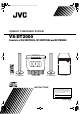
VS-DT2000(J)_EN.book Page 1 Wednesday, February 6, 2002 4:37 PM COMPACT COMPONENT SYSTEM VS-DT2000 Consists of CA-VSDT2000, SP-VSDT2000 and SP-PW2000 COMPACT COMPONENT SYSTEM STANDBY/ON 1 2 3 PLAY MODE 4 5 6 7 8 9 REPEAT FM MODE 10 +10 BASS TREBLE SET CANCEL MD/AUX FM/AM DISPLAY DIMMER COLOR CLOCK /TIMER OPEN/ CLOSE SLEEP VOLUME RM-SVSDT2000J REMOTE CONTROL SP-VSDT2000 CA-VSDT2000 SP-VSDT2000 INSTRUCTIONS SP-PW2000 For Customer Use: Enter below the Model No.
VS-DT2000(J)_EN.book Page 1 Wednesday, February 6, 2002 4:37 PM Warnings, Cautions and Others / Mises en garde, précautions et indications diverses (For U.S.A) CAUTION RISK OF ELECTRIC SHOCK DO NOT OPEN CAUTION: TO REDUCE THE RISK OF ELECTRIC SHOCK DO NOT REMOVE COVER (OR BACK) NO USER SERVICEABLE PARTS INSIDE REFER SERVICING TO QUALIFIED SERVICE PERSONNEL.
VS-DT2000(J)_EN.book Page 2 Wednesday, February 6, 2002 4:37 PM For Canada/pour le Canada For Canada/pour Le Canada CAUTION: TO PREVENT ELECTRIC SHOCK, MATCH WIDE BLADE OF PLUG TO WIDE SLOT, FULLY INSERT. THIS DIGITAL APPARATUS DOES NOT EXCEED THE CLASS B LIMITS FOR RADIO NOISE EMISSIONS FROM DIGITAL APPARATUS AS SET OUT IN THE INTERFERENCE-CAUSING EQUIPMENT STANDARD ENTITLED “DIGITAL APPARATUS,” ICES-003 OF THE DEPARTMENT OF COMMUNICATIONS.
VS-DT2000(J)_EN.book Page 1 Wednesday, February 6, 2002 4:37 PM Introduction Thank you for purchasing the JVC Compact Component System. We hope it will be a valued addition to your home, giving you years of enjoyment. Be sure to read this instruction manual carefully before operating your new stereo system. In it you will find all the information you need to set up and use the system. If you have a query that is not answered by the manual, please contact your dealer.
VS-DT2000(J)_EN.book Page 2 Wednesday, February 6, 2002 4:37 PM Table of Contents Introduction ........................................................................................................ 1 Features ...................................................................................................................................... 1 How This Manual Is Organized ................................................................................................. 1 WARNINGS .........................
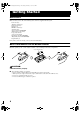
VS-DT2000(J)_EN.book Page 3 Wednesday, February 6, 2002 4:37 PM Getting Started Accessories Make sure that you have all of the following items, which are supplied with the System.
VS-DT2000(J)_EN.book Page 4 Wednesday, February 6, 2002 4:37 PM Getting Started CAUTION: • Make all connections before plugging the System into an AC power outlet. (Only if you install the Center Unit vertically) • To place the Center Unit vertically, the Stand and Legs must be attached. (See page 8.) To make connections, let the cords pass in the holes of the Stand as shown in the diagram before attaching the Stand and Legs.
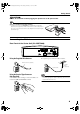
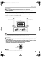
VS-DT2000(J)_EN.book Page 5 Wednesday, February 6, 2002 4:37 PM Getting Started Connecting the AM Antenna Rear Panel of the Center Unit (CA-VSDT2000) SPEAKERS ANTENNA FM (75 ) COAXIAL H V L R DISP.SET SPEAKER IMPEDANCE 4 CD DIGITAL OUT 16 SUB WOOFER AM LOOP MD/AUX OUT IN AM EXT AC IN AM loop antenna (Supplied) ANTENNA FM (75 ) COAXIAL AM LOOP AM EXT Outdoor single vinylcovered wire (not supplied) Attach the AM loop to its base by snapping the tabs on the loop into the slot in the base.
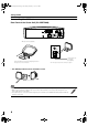
VS-DT2000(J)_EN.book Page 6 Wednesday, February 6, 2002 4:37 PM Getting Started CAUTION: • Make all connections before plugging the System into an AC power outlet. • Handling the speakers As this is a precision instrument, handle it carefully so as to protect it from shocks. Connecting the Speakers (SP-VSDT2000) These speakers are exclusively for this system. Using with other devices will damege the speakers. 1. Open each of the terminals to connect the speaker wire leads. 2.
VS-DT2000(J)_EN.book Page 7 Wednesday, February 6, 2002 4:37 PM Getting Started Attaching the Spacers Attach the supplied spacers to the bottom of the powered subwoofer (SP-PW2000) to protect the cabinet, prevent slipping, and absorb the cabinet vibration. Peel off the backing from a spacer and attach it.
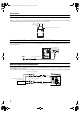
VS-DT2000(J)_EN.book Page 8 Wednesday, February 6, 2002 4:37 PM Getting Started Connecting an MD Recorder, etc (Digital Output) Remove the cap and connect an optical digital cord (not supplied) between the System’s CD DIGITAL OUT terminal and the input terminal of the MD recorder, etc. You can record the digital output signal from the System’s CD Player to the MD recorder, etc. Cap MD recorder, etc.
VS-DT2000(J)_EN.book Page 9 Wednesday, February 6, 2002 4:37 PM Getting Started Installing the Equipment on the Wall The Center Unit and Speakers can be attached to a wall. CAUTIONS: Attachment to a wall • The Center Unit weighs approximately 4.3 kg (9.5 lbs). When its buttons are operated, an additional force will be applied to it in the downward direction. Therefore, sufficient care must be taken when attaching to a wall to prevent any accidents caused by the Center Unit’s falling off the wall.
VS-DT2000(J)_EN.book Page 10 Wednesday, February 6, 2002 4:37 PM Getting Started Example of attachment (Speakers) The speakers can be attached to a wall. Attach the bracket (supplied) to the wall using two screws (not supplied) and place the Speaker onto the bracket. Then, use the wing bolt (supplied) to fix the Speaker firmly to the brakcet. Wall Screws (not supplied) Bracket (supplied) Wing bolt (supplied) • Do not place anything on top of the Center Unit.
VS-DT2000(J)_EN.book Page 11 Wednesday, February 6, 2002 4:37 PM Getting Started Using the Remote Control The Remote Control makes it easy to use many of the functions of the System from a distance of up to 7 m (23 feet) away. The remote sensor at which you need to point the Remote Control differs depending on whether the Unit is placed vertically or horizontally.
VS-DT2000(J)_EN.
VS-DT2000(J)_EN.book Page 13 Wednesday, February 6, 2002 4:37 PM Basic Operations Changing the Color (COLOR) Tone Control (BASS/TREBLE) (Using the Remote Control) You can change the color of the illumination on the Unit. (Using the Remote Control) You can control the tone by changing the bass and treble. 1 2 Press the % button to turn on the System. Press the COLOR button on the Remote Control. BASS Control You can adjust the bass level (low frequency range level) between –5 and +5.
VS-DT2000(J)_EN.book Page 14 Wednesday, February 6, 2002 4:37 PM Using the Powered Subwoofer STANDBY/ON indicator VOLUME PHASE INPUT (LOW-LEVEL) INPUT (HIGH-LEVEL) POWER Operating the Powered Subwoofer Presetting the Volume You need to preset the volume level of this speaker (SPPW2000) to match those of the main speakers (SPVSDT2000).
VS-DT2000(J)_EN.book Page 15 Wednesday, February 6, 2002 4:37 PM Using the Powered Subwoofer INPUT Terminals The Subwoofer has the following INPUT terminals. INPUT(LOW-LEVEL): Usually, the LEFT/MONO terminal is connected to the SUBWOOFER terminal of the Center Unit with the supplied signal cord. (see page 7.) When the Center Unit CA-VSDT2000 is not used (Using other equipment) If an amplifier etc.
VS-DT2000(J)_EN.
VS-DT2000(J)_EN.book Page 17 Wednesday, February 6, 2002 4:37 PM Using the Tuner Presetting Stations (Using the Remote Control) You can preset up to 30 FM stations and up to 15 AM stations. • Preset numbers may have been set to factory test frequencies prior to shipment. This is not a malfunction. You can preset the stations you want into memory by following one of the presetting methods below.
VS-DT2000(J)_EN.
VS-DT2000(J)_EN.book Page 19 Wednesday, February 6, 2002 4:37 PM Using the CD Player To Select a Track or Passage within a Track To Unload a CD Press the 0 button on the Unit to eject a CD. The CD is ejected automatically, then take out the CD.
VS-DT2000(J)_EN.book Page 20 Wednesday, February 6, 2002 4:37 PM Using the CD Player 5 Press the Number button to select the track to program. Random Play Each time you press the Number button, the selected track is added to the program. • For the track number more than 10, press the +10 button then the Number button. (Using the Remote Control) The tracks will play in no special order when you use this mode. • To enter Random Play mode, stop playback first.
VS-DT2000(J)_EN.book Page 21 Wednesday, February 6, 2002 4:37 PM Using External Equipment STANDBY/ON 1 2 3 PLAY MODE 4 5 6 7 8 9 REPEAT FM MODE 10 +10 BASS TREBLE SET MD/AUX CANCEL MD/AUX SOURCE FM/AM DISPLAY DIMMER COLOR CLOCK /TIMER OPEN/ CLOSE PRESET VOL SLEEP SOURCE VOLUME RM-SVSDT2000J REMOTE CONTROL Listening to External Equipment You can listen to external equipment such as MD recorder, cassette deck or other auxiliary.
VS-DT2000(J)_EN.book Page 22 Wednesday, February 6, 2002 4:37 PM Using the Timers STANDBY/ON 1 2 3 PLAY MODE 4 5 6 7 8 9 REPEAT ON time, OFF time, Source, Volume FM MODE 10 +10 BASS TREBLE SET SET MD/AUX CANCEL SLEEP CLOCK /TIMER FM/AM DISPLAY DIMMER COLOR CLOCK /TIMER OPEN/ CLOSE SLEEP Timer indicator SLEEP indicator SLEEP VOLUME RM-SVSDT2000J REMOTE CONTROL * When the System is in use, the display shows other items as well.
VS-DT2000(J)_EN.book Page 23 Wednesday, February 6, 2002 4:37 PM Using the Timers Setting the Daily Timer 2 Setting the OFF time (Example: PM 1:30). (Using the Remote Control) Once you have set the Daily Timer, the timer will be activated at the same time every day. 1. Press the SET button. The hour digit of the OFF time blinks on the display. (The same time as the ON time will be automatically set.) The Timer indicator ( ) on the display shows that the Daily Timer you have set is in effect.
VS-DT2000(J)_EN.book Page 24 Wednesday, February 6, 2002 4:37 PM Using the Timers 6 Before turning off the System, prepare the music source selected in step 3. TUNER: Tune in to the desired station. CD: Insert a CD. (Playback will start from the first track at Timer on.) 7 Press the % button to turn off the System. In standby mode, you can see the Timer indicator ( ) on the display. • When the timer turns on, the Timer indicator starts blinking and the prepared source in step 6 will be played.
VS-DT2000(J)_EN.book Page 25 Wednesday, February 6, 2002 4:37 PM Care And Maintenance Handle your CDs carefully, and they will last a long time. Compact Discs • Only CDs bearing this mark can be used with this System. However, continued use of irregular shape CDs (heart-shape, octagonal, etc.) can damage the System. • Remove the CD from its case by holding it at the edges while pressing the case’s center hole lightly. • Do not touch the shiny surface of the CD, or bend the CD.
VS-DT2000(J)_EN.book Page 26 Wednesday, February 6, 2002 4:37 PM Troubleshooting • If you are having a problem with your System, check this list for a possible solution before calling for service. Symptom No sound is heard. • If you cannot solve the problem from the hints given here, or the System has been physically damaged, call a qualified person, such as your dealer, for service. Possible Cause • Connections are incorrect, or loose. Action • Headphones are connected.
Warranty.
Warranty.
VS-DT2000(J)_EN.book Page 27 Wednesday, February 6, 2002 4:37 PM Specifications CA-VSDT2000 Amplifier Output Power 19 W per channel, min.