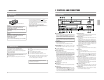
CONTROLS AND CONNECTORS CONNECTIONS SR-9080 PREPARATION INSTRUCTIONS SR-9080U STOP REC CHECK EJECT PLAYBACK AND SPECIAL-EFFECTS PLAYBACK REC REC ON-SCREEN/MENU SWITCHES VIDEO CASSETTE RECORDER RECORDING SR-9080 VIDEO CASSETTE RECORDER INTRODUCTION R OPERATE OPERATE For Customer Use: Enter below the Serial No. which is located on the rear of cabinet. Retain this information for future reference. R is a registered trademark owned by VICTOR COMPANY OF JAPAN, LTD.
E model SAFETY PRECAUTIONS : U model SAFETY PRECAUTIONS CAUTION ATTENTION RISK OF ELECTRIC SHOCK DO NOT OPEN RISQUE D’ELECTROCUTION NE PAS OUVRIR Warning Notice FOR YOUR SAFETY (Australia) CAUTION: TO REDUCE THE RISK OF ELECTRIC SHOCK, DO NOT REMOVE COVER (OR BACK). NO USER-SERVICEABLE PARTS INDIDE.
CONTENTS OPERATION LOCK 1 INTRODUCTION 1-1 1-2 1-3 1-4 By engaging the operation lock system [LOCK], you can prevent accidental or deliberate interference with recording operation or power supply. When this function is activated, all operation buttons are disabled. However, you can still control the recorder with the remote control. Major Features ............................................. Periodical Maintenance................................ Precautions ..............................................
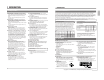
1 INTRODUCTION 1 INTRODUCTION 1-1 Major Features 5 Extended timelapse recording for up to 960 hours : U model Recording times are selectable from 2 hours (SP mode), 6 hours (EP mode) and L12/L18/L24/24/48/72/120/168/ 240/480/960 (Timelapse mode) (when T-120 tape is used). In the L12, L18 and L24 Timelapse modes, sound is recorded as well.
2 CONTROLS AND CONNECTORS 1 INTRODUCTION 1-3 Precautions 2-1 Front Panel 7 Video cassette Erasure prevention tab U model Timelapse recording is performed over very long periods of time which means that a durable tape is required. When using VHS tapes, do not use tapes with recording times of more than 160 minutes (T160/T-180). • Only use video cassette bearing the mark. • To prevent accidental erasure of a recorded tape, break the erasure prevention tab on the cassette.
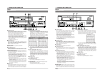
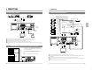
2 CONTROLS AND CONNECTORS 2 CONTROLS AND CONNECTORS U model E model 2-1 Front Panel 2-1 Front Panel 24 24 25 26 25 SR-9080E SR-9080U REC REC REC REC STOP REC CHECK HDR REW REVERSE PAUSE PLAY ON SCREEN MENU TIME MODE FIELD ADV STOP OPERATE REC CHECK REW REVERSE PAUSE PLAY – V.
2 CONTROLS AND CONNECTORS 2 CONTROLS AND CONNECTORS U model E model 2-2 Display 2-2 Display 1 2 6 7 8 3 1 13 2 5 Playback Recording Rewind Fastforward Timelapse playback Still Recordpause Rewind search Fast-forward search Reverse playback ) mark in the Rec/Pause mode is shown in red. Cassette indication Lights when a cassette is loaded. Blinks when a cassette is being ejected. 3 [SP/EP] indication Shows the standard (SP) mode or extended (EP) mode during recording/playback.
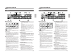
2 CONTROLS AND CONNECTORS 2 CONTROLS AND CONNECTORS 2-1 FRONT PANEL 2-3 Rear Panel 2-3 Rear Panel 4 6 % [COM] common ground terminal Connect to the signal ground terminal of a connected unit.
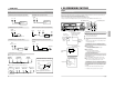
3 CONNECTIONS 3 CONNECTIONS 3-1 Connecting to a Camera 3-2 System Using Sequential Switcher CCD Amplifier Microphone Video camera Video camera RCA BNC CCD Microphone 1 M3.
4 ON-SCREEN/MENU SWITCHES 3 CONNECTIONS U model 3-3 Connecting the Rear Panel Input/Output Terminal Connections [CAM SW OUT] camera switching signal output terminal 4-1 On-Screen Display Displays the time date (date and time), recording speed, number of alarms and number of power losses (power failures) on screen in the Stop mode, Record mode and Record-Pause mode. During recording, the on-screen data is recorded together with video signals.
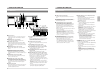
4 ON-SCREEN/MENU SWITCHES 4 ON-SCREEN/MENU SWITCHES E model 4-1 On-Screen Display 4-2 Main Menu Display Displays the time date (date and time), recording speed, number of alarms and number of power losses (power failures) on screen in the Stop mode, Record mode and Record-Pause mode. During recording, the on-screen data is recorded together with video signals. • The on-screen display position can be moved with the [ON SCREEN] buttons.
4 ON-SCREEN/MENU SWITCHES 4 ON-SCREEN/MENU SWITCHES 4-3 Date and Time Setting 4-3 Date and Time Setting The time/date generator and timer recording will not function if the time and date are not set. Set the month/day/year, hour/minute and Summer Time Compensation ON/OFF on the CLOCK SET screen. The setting can be checked even on the display. SR-9080U REC REC STOP REC CHECK Cursor indication RESET/ CANCEL MENU TIME MODE During daylight savings time 1 Set the time with a one-hour delay.
4 ON-SCREEN/MENU SWITCHES 4 ON-SCREEN/MENU SWITCHES 4-5 Alarm Input/Power Loss Data Display 4-6 Menu Switch Setting The dates and times of up to 8 alarm inputs or 4 power losses (failures) can be displayed. Operation 1 Turn on the VCR and monitor. 2 Press the [MENU] button to display the main menu on the [MENU] CLOCK SET ONSCREEN/F. DISP MODE VIDEO/VTR MODE SRI/EXT MODE BUZZER/IN OUT PROGRAM TIMER HOLIDAY SET HOUR METER Cursor indication 3 Press the [SHIFT 7] button to set the cursor on .
4 ON-SCREEN/MENU SWITCHES 4 ON-SCREEN/MENU SWITCHES 4-7 Contents of Menu Switches 4-7 Contents of Menu Switches [ ]: Factory setting Screens ON SCREEN MODE Items Set values TONE 0 IRE 30 IRE 70 IRE [100] IRE (VCR's display) 05D 05D VIDEO MODE [ON] OFF ON OFF 2 [ON] OFF ON OFF 3 REC SPEED ON [OFF] 05D ON OFF 4 ALARM CNT ON [OFF] 05D ON OFF 5 POWER LOSS CNT [ON] OFF 05D ON OFF 6 REC TALLY [ON] OFF FDiP ON OFF 1 WARNING [ON] OFF FDiP ON OFF 2 V.
4 ON-SCREEN/MENU SWITCHES 4 ON-SCREEN/MENU SWITCHES 4-7 Contents of Menu Switches • The lower section in the items and set values columns shows what’s on the VCR’s display. [ ]: Factory setting Screens SRI/EXT MODE Items Set values SRI/EXT REC [OFF] SERIES EXT (VCR's display) OFF SERI EIT nly SR ET 1 EXT REC END [NORMAL] OPE OFF SR NORn POFF ET 2 CNT TAPE END [OFF] 500 1000 . .. 9500 SR ALARM/ SENSOR MODE 4-7 Contents of Menu Switches ET 3 REC MODE AL SE OFF 500 . ..
5 PREPARATION 5 PREPARATION U model 5-1 Cassette Loading/Unloading 5-2 Recording/Playback Speed Mode Selection Loading SR-9080U Insert the cassette with its label side facing you. Gently push the center of the cassette until the machine starts automatic loading. REC REC STOP REC CHECK FIELD REV RESET/ CANCEL ON SCREEN MENU TIME MODE FF FIELD ADV OPERATE SHIFT TRACKING SR-9080U EJECT OPERATE HDR REW REVERSE PAUSE PLAY – + V.
6 RECORDING 5 PREPARATION E model 5-2 Recording/Playback Speed Mode Selection 6-1 Switch Setting During Recording [ON SCREEN 7] button [ON SCREEN f] button SR-9080U SR-9080E REC REC REC STOP REC CHECK REW REVERSE PAUSE PLAY EJECT OPERATE REC RESET/ CANCEL ON SCREEN MENU TIME MODE FF STOP REC CHECK V.
6 RECORDING 6 RECORDING U model 6-2 Recording Basic Operation [REC] button 6-3 Timer Recording [STOP] button [REC CHECK] button This unit is provided with 2 different setting screens for timer recording program; one allows you to specify the day of week, the other allows you to specify a date (a holiday, for example). You can select the desired setting screen from the main menu screen. • Program timer setting: Day-of-the-week (Sun. to Sat.
6 RECORDING 6 RECORDING E model U model 6-3 Timer Recording 6-3 Timer Recording 5 Press the [SHIFT 7] button to select
6 RECORDING 6 RECORDING E model U model 6-3 Timer Recording 6-3 Timer Recording 3 Press the [SHIFT 7] button to select in the main menu and press the [SET +/–] button. [The menu is shown on the monitor and “SUN” blinks. Main menu screen [MENU] 4 Set the day of the week (SAT). CLOCK SET ONSCREEN/F. DISP MODE VIDEO/VTR MODE Press the [SET +/–] button to set the day of the week to “SAT”.
6 RECORDING 6 RECORDING E model U model 6-3 Timer Recording 6-3 Timer Recording [SHIFT 7] button 5 Programming timer recording for more than one day [SHIFT f] button PROGRAM TIMER screen SR-9080E RESET/ CANCEL REC REC STOP REC CHECK REW REVERSE PAUSE PLAY RESET/ CANCEL ON SCREEN MENU TIME MODE FF Recording speed Stop time Start time Day of the week SHIFT OPERATE MENU TIME MODE FIELD ADV + – V.
6 RECORDING 6 RECORDING E model 6-3 Timer Recording 6-3 Timer Recording [SHIFT 7] button 5 Programming timer recording for more than one day PROGRAM TIMER screen (every day) This programming is to timer-record at the same time on specified days of the week.
6 RECORDING 6 RECORDING 6-3 Timer Recording 6-3 Timer Recording Notes on Timer Recording [SHIFT 7] button [SHIFT f] button [RESET/CANCEL] button SR-9080U REC REC STOP REC CHECK HDR REW REVERSE PAUSE PLAY RESET/ CANCEL ON SCREEN MENU TIME MODE FF FIELD ADV program is set and the [TIMER] button is pressed, the TIMER indication blinks for about 10 seconds and a warning buzzer sounds if in the menu is set to “ON”.
6 RECORDING 6 RECORDING 6-4 Alarm Recording 6-4 Alarm Recording Alarm recording functions during timelapse recording. When an alarm signal is input to the rear panel’s ALARM IN terminal, an index code is recorded on the tape and the VCR automatically switches to the 2H (SP) or 6H (EP) mode : U model, 3H (SP) mode : E model for realtime recording of the alarm situation. Normal timelapse recording is restored after the preset alarm recording duration has passed.
6 RECORDING 6 RECORDING 6-5 Sensor Recording 6-6 Series Recording Sensor recording is executed only when the VCR is in the Stop mode (Stop, Timer Record Standby or Operating Off mode) and an alarm signal is input to the rear panel’s ALARM IN terminal. Perform the settings for sensor recording in the same way as for “Alarm Recording” on page 39. The mechanism of the SR-9080 cannot be guaranteed if the sensor recording function is used frequently (100 times/day or more).
6 RECORDING 6 RECORDING 6-6 Series Recording 6-7 Repeat Recording 5 When the first VCR ends recording, the second VCR starts recording automatically, then the third and so on. • When the tape end output is set, series recording signals are output from the [SERIES REC OUT] terminal at the specified tape reel counter value, signaling the next VCR to start recording. The first VCR continues recording until the tape ends.
6 RECORDING 6 RECORDING 6-8 Recording with External VCR Activation Signal 6-9 How to Restore Recording After Power Failure Recording start/stop can be controlled externally by inputting a VCR activation signal to the [SERIES REC IN] terminal on the SR-9080’s rear panel. * If the external recording function is activated a hundred times a day or more, a malfunction may occur because the guaranteed range is exceeded.
7 PLAYBACK AND SPECIAL-EFFECTS PLAYBACK 7 PLAYBACK AND SPECIAL-EFFECTS PLAYBACK U model E model [STOP] button [STOP] button Playback mode indicator Playback mode indicator [OPERATE] indicator [OPERATE] indicator SR-9080U SR-9080E REC REC STOP REC CHECK RESET/ CANCEL FIELD ADV OPERATE REC – + – TIMER SEARCH DISPLAY LOCK CNT RESET + MENU REC CHECK REW REVERSE PAUSE PLAY SHIFT V.
7 PLAYBACK AND SPECIAL-EFFECTS PLAYBACK 7 PLAYBACK AND SPECIAL-EFFECTS PLAYBACK 7-3 Special-Effects Playback SR-9080U REC SR-9080U REC STOP REC CHECK RESET/ CANCEL ON SCREEN MENU TIME MODE FF OPERATE SHIFT TRACKING FIELD REV EJECT OPERATE HDR REW REVERSE PAUSE PLAY REC FIELD ADV – + V.
7 PLAYBACK AND SPECIAL-EFFECTS PLAYBACK 7 PLAYBACK AND SPECIAL-EFFECTS PLAYBACK Alarm scan SR-9080U The section around the start of each alarm recording is played back for about 5 seconds. * Playback may start a few seconds after the actual start of the alarm recording. * If the interval between alarm recordings is short, the tape may play back continuously for 5 seconds or more. * Sound is not output.
7 PLAYBACK AND SPECIAL-EFFECTS PLAYBACK 7 PLAYBACK AND SPECIAL-EFFECTS PLAYBACK 7-5 Repeat Playback SR-9080U REC The tape is automatically rewound and played back repeatedly. • To execute repeat playback, set in to “ON”. VIDEO/VTR MODE screen OFF [VTR MODE] 1. HDR OFF 2. CNT MEM SW OFF 3. POWER ON REC OFF 4. AUTO REC CHECK OFF 5. AUTO REW OFF 6. REPEAT PLAY ON 7.
8 TROUBLESHOOTING 8 TROUBLESHOOTING U model 8-1 Error Indication 8-2 No Error Indication Symptoms Error indications are shown on the display whenever condensation occurs or there are problems with cassette loading, unloaxding or mechanism operation. Display section No power is supplied. 5 When a problem occurs, the error indication “E-**” lights (when the menu switch in is set to “ON”).
9 OPTIONAL SA-K97U RS-232C INTERFACE BOARD 8 TROUBLESHOOTING E model Functions that can be controlled with front panel buttons and switches can also be controlled from a personal computer when the optional SA-K97U RS-232C interface board is installed. Operation status can also be monitored on the computer. 8-2 No Error Indication Symptoms No power is supplied. Operation buttons have no effect during recording and playback. No picture is shown during playback.
9 OPTIONAL SA-K97U RS-232C INTERFACE BOARD 9 OPTIONAL SA-K97U RS-232C INTERFACE BOARD 9-2 SA-K97U Specifications 9-3 SA-K97U RS-232C Protocol & Commands 9-pin connector specifications RS-232C protocol Pin NO. Signals 2 RXD Receive data VTR p CPU 3 TXD Transmit data VTR [ CPU 4 DTR Data terminal ready VTR [ CPU 5 GND Signal ground 6 DSR Data set ready Operations This VCR is provided with JVC basic table commands in addition to the JVC table-1 commands shown below.
9 OPTIONAL SA-K97U RS-232C INTERFACE BOARD 9 OPTIONAL SA-K97U RS-232C INTERFACE BOARD U model After transmitting the VISS SEARCH command (18), transmit the appropriate 2-byte numeric data (from 30H to 39H), the data input command (40H), and either FF (ABH) or REW (ACH). All commands should be transmitted separately one byte at a time with “ACK” (0AH) confirmation from the VCR after each transmission. * Execute in the Stop mode.
9 OPTIONAL SA-K97U RS-232C INTERFACE BOARD 9 OPTIONAL SA-K97U RS-232C INTERFACE BOARD E model After transmitting the VISS SEARCH command (18), transmit the appropriate 2-byte numeric data (from 30H to 39H), the data input command (40H), and either FF (ABH) or REW (ACH). All commands should be transmitted separately one byte at a time with “ACK” (0AH) confirmation from the VCR after each transmission. * Execute in the Stop mode.
9 OPTIONAL SA-K97U RS-232C INTERFACE BOARD 9 OPTIONAL SA-K97U RS-232C INTERFACE BOARD U model 3 Commands for VCR status verification When the command is sent, the VCR returns the corresponding information. (9) STATUS SENSE (D7H) : The VCR will return current status information in 5 bytes.
9 OPTIONAL SA-K97U RS-232C INTERFACE BOARD 9 OPTIONAL SA-K97U RS-232C INTERFACE BOARD E model (9) STATUS SENSE (D7H) : The VCR will return current status information in 5 bytes. 4 Others (Input data correction/Error cancellation) These are return codes from the SR-9080. (Error-related codes only) 1st byte BIT 0 Error 1 2 3 4 Not defined Not defined Cassette out REC inhibit 5 Not defined 6 Not defined 7 Not defined Status when BIT is “1”. Indicates that an illegal command has been received.
10 APPENDIXES 10 APPENDIXES U model E model 10-1 Tape Reel Counter/Tape Remaining Time Table 10-1 Tape Reel Counter/Tape Remaining Time Table The table below shows the tape remaining time with the tape reel counter value in each record/playback speed mode (when a T120 tape is used). Since actual tape remaining time may differ from the values in the table below, use these values for reference only.
Terminals CAM SW OUT Camera switching signal output Signal levels During recording Remarks The switching interval can be set to“1 field” or “1 frame”with the in the setting screen. (With the menu switch set to “1 field”) (Timelapse recording) 1 field During standby GND 5m sec Time Camera switching signal output Open-collector output HV: 5 V ALARM IN Alarm signal input Input at ground level LV: 0 V Min. 400 msec.