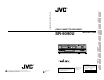
CONNECTIONS CONTROLS AND CONNECTORS SR-9090U PREPARATION INSTRUCTIONS ON-SCREEN/MENU SWITCHES VIDEO CASSETTE RECORDER RECORDING SR-9090U VIDEO CASSETTE RECORDER INTRODUCTION R SR-9090U REC STOP REC CHECK EJECT PLAYBACK AND SPECIAL-EFFECTS PLAYBACK REC OPERATE OPERATE R Thank you for purchasing this JVC product. Before operating this unit, please read the instructions carefully to ensure the best possible performance.
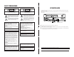
SAFETY PRECAUTIONS OPERATION LOCK CAUTION ATTENTION RISK OF ELECTRIC SHOCK DO NOT OPEN RISQUE D’ELECTROCUTION NE PAS OUVRIR CAUTION: TO REDUCE THE RISK OF ELECTRIC SHOCK, DO NOT REMOVE COVER (OR BACK). NO USER-SERVICEABLE PARTS INDIDE. REFER SERVICING TO QUALIFIED SERVICE PERSONNEL By engaging the operation lock system [LOCK], you can prevent accidental or deliberate interference with recording operation or power supply. ATTENTION: POUR EVITER TOUT RISQUE D’ELECTROCUTION NE PAS OUVRIR LE BOITER.
CONTENTS 1 INTRODUCTION 1-1 Major Features ............................................. 6 1-2 Periodical Maintenance ................................ 7 1-3 Precautions .................................................. 7 1-4 Daily Inspection ............................................ 8 2 CONTROLS AND CONNECTORS 2-1 Front Panel .................................................. 9 2-2 Display ....................................................... 11 2-3 Rear Panel ........................................
For servicing → See page 2-2 “MAINTENANCE AND CHECK” 1 INTRODUCTION 1 INTRODUCTION 1-1 Major Features 5 Extended timelapse recording for up to 960 hours Recording times are selectable from 2 hours (SP mode), 6 hours (EP mode) and 24/48/72/120/168/240/480/960 (Timelapse mode) (when T-120 tape is used). 5 High-resolution recording Delivers horizontal resolution of more than 400 lines even in color mode. *When a tape recorded on this unit is played back on another VCR, noise may appear on playback picture.
2 CONTROLS AND CONNECTORS 1 INTRODUCTION 1-3 Precautions 2-1 Front Panel 7 Video cassette Erasure prevention tab Timelapse recording is performed over very long periods of time which means that a durable tape is required. When using VHS tapes, do not use tapes with recording times of more than 120 minutes (T-160/T-180 etc.). For best results, use a T-120 tape. • Only use video cassette bearing the mark.
2 CONTROLS AND CONNECTORS 2 CONTROLS AND CONNECTORS 2-1 Front Panel 2-2 Display 24 1 25 26 6 7 8 9 10 11 12 13 SR-9090U REC REC STOP REC CHECK HDR REW REVERSE PAUSE PLAY RESET/ CANCEL ON SCREEN MENU TIME MODE FF FIELD ADV OPERATE SHIFT TRACKING FIELD REV EJECT OPERATE – + V. LOCK – TIMER SEARCH DISPLAY LOCK CNT RESET + – SET 2 + 3 4 1 Operation mode display Shows the operation modes.
2 CONTROLS AND CONNECTORS 2 CONTROLS AND CONNECTORS 2-1 FRONT PANEL 2-3 Rear Panel 2-3 Rear Panel 4 6 8 ^ [TAPE END OUT] tape end signal output terminal 1 AC~IN AC120V~50/60Hz RS-232C VIDEO AUDIO Y/C CLOCK COM SERIES CAM SW ALARM ALARM RESET IN REC IN REC OUT IN OUT ALARM SERIES TAPE WARNING CLOCK COM RESET END OUT OUT RESET OUT REC OUT IN REMOTE MIC OUT 2 3 5 7 9 10 COM CLOCK SERIES CAM SW ALARM ALARM RESET IN REC IN REC OUT IN OUT ALARM SERIES TAPE WARNING CLOCK COM RESET END OUT OUT RESE
3 CONNECTIONS 3 CONNECTIONS 3-1 Connecting to a Camera 3-2 System Using Sequential Switcher Video camera CCD CCD Microphone 1 Amplifier 2 3 4 5 Alarm sensor input RCA Alarm sensor 1 2 3 4 5 6 CCD BNC Alarm signal output 4pin Microphone 6 Video camera M3.
4 ON-SCREEN/MENU SWITCHES 3 CONNECTIONS 3-3 Connecting the Rear Panel Input/Output Terminal Connections [CAM SW OUT] camera switching signal output terminal 4-1 On-Screen Display Displays the time date (date and time), recording speed, number of alarms and number of power losses (power failures) on screen in the Stop mode, Record mode and Record-Pause mode. During recording, the on-screen data is recorded together with video signals.
4 ON-SCREEN/MENU SWITCHES 4 ON-SCREEN/MENU SWITCHES 4-2 Main Menu Display 4-3 Date and Time Setting You can display date and time data recorded when an alarm input or power failure occurs, as well as the hour meter (drum rotating time) by selecting the desired item in the main menu. The date/time setting screen, menu switch setting screen for each application, and timer recording program setting screen can also be displayed by selecting the desired item in the main menu.
4 ON-SCREEN/MENU SWITCHES 4 ON-SCREEN/MENU SWITCHES 4-3 Date and Time Setting 4-5 Alarm Input/Power Loss Data Display Summer Time Compensation • When setting the time, make sure the item is set to “OFF”. When this unit is shipped, this item is set to “OFF”. The dates and times of up to 8 alarm inputs or 4 power losses (failures) can be displayed. Operation Standard time During daylight savings time 1 Set the time with a one-hour delay.
4 ON-SCREEN/MENU SWITCHES 4 ON-SCREEN/MENU SWITCHES 4-6 Menu Switch Setting 4-7 Contents of Menu Switches You can customize the VCR’s functions to suit the requirements of your application using the four menu switch setting screens accessible from the main menu screen. • ON SCREEN/F. DISPLAY MODE • VIDEO/VTR MODE • SRI/EXT, ALARM/SENSOR MODE • BUZZER/IN OUT Each menu switch setting screen can be accessed independently from the main menu.
4 ON-SCREEN/MENU SWITCHES 4 ON-SCREEN/MENU SWITCHES 4-7 Contents of Menu Switches 4-7 Contents of Menu Switches [ ]: Factory setting Screens VIDEO MODE • The lower section in the items and set values columns shows what’s on the VCR’s display. Items V.
5 PREPARATION 4 ON-SCREEN/MENU SWITCHES 4-7 Contents of Menu Switches [ ]: Factory setting Screens ALARM/ SENSOR MODE • The lower section in the items and set values columns shows what’s on the VCR’s display. Items Set values DURATION 5 SEC 10 SEC 15 SEC 30 SEC 60 SEC 120 SEC [180 SEC] TAPE END MANUAL (VCR's display) AL SE 3 TAPE END MODE AL BUZZER SE 4 22 OFF STOP [OFF] ON 1 OFF ON AL/SENSOR IN [OFF] ON BU OFF ON 22 2 WARNING BU IN/OUT 5 .. .
6 RECORDING 5 PREPARATION 5-2 Recording/Playback Speed Mode Selection 6-1 Switch Setting During Recording [ON SCREEN f] button [ON SCREEN 7] button SR-9090U SR-9090U REC REC STOP REC CHECK HDR REW REVERSE PAUSE PLAY RESET/ CANCEL ON SCREEN MENU TIME MODE FF REC OPERATE FIELD ADV – + V.
6 RECORDING 6 RECORDING 6-2 Recording Basic Operation 6-3 Timer Recording [STOP] button [REC] button This unit is provided with 2 different setting screens for timer recording program; one allows you to specify the day of week, the other allows you to specify a date (a holiday, for example). You can select the desired setting screen from the main menu screen. • Program timer setting: Day-of-the-week (Sun. to Sat.
6 RECORDING 6 RECORDING 6-3 Timer Recording 6-3 Timer Recording 5 Press the [SHIFT 7] button to select
6 RECORDING 6 RECORDING 6-3 Timer Recording 6-3 Timer Recording [SHIFT 7] button 5 Programming timer recording for more than one day PROGRAM TIMER screen Recording speed Stop time Start time ON: Enabled Day of the week OFF: Disabled * * * * [ P ROGRAM * T I ME R ] * * * * * * * * * S T AR T * S T OP * * S P D * * PGM S UN 0 – – : – – : – – : – – * – – – – 1 – – – MON 0 – – : – – : – – : – – * – – – – 6 – – – T UE 0 – – : – – : – – : – – * – – – – 5 – – – WE D – – – : – – : – – : – – * – – – – – – – – T
6 RECORDING 6 RECORDING 6-3 Timer Recording 6-3 Timer Recording Notes on Timer Recording [SHIFT 7] button [SHIFT f] button [RESET/CANCEL] button SR-9090U REC REC STOP REC CHECK HDR REW REVERSE PAUSE PLAY RESET/ CANCEL ON SCREEN MENU TIME MODE FF FIELD ADV program is set and the [TIMER] button is pressed, the TIMER indication blinks for about 10 seconds and a warning buzzer sounds if in the menu is set to “ON”.
6 RECORDING 6 RECORDING 6-4 Alarm Recording 6-4 Alarm Recording Alarm recording functions during timelapse recording. When an alarm signal is input to the rear panel’s ALARM IN terminal, an index code is recorded on the tape and the VCR automatically switches to the 2H (SP) or 6H (EP) mode for realtime recording of the alarm situation. Normal timelapse recording is restored after the preset alarm recording duration has passed. set the alarm recording-related menu switches.
6 RECORDING 6 RECORDING 6-5 Sensor Recording 6-6 Series Recording Sensor recording is executed only when the VCR is in the Stop mode (Stop, Timer Record Standby or Operating Off mode) and an alarm signal is input to the rear panel’s ALARM IN terminal. Perform the settings for sensor recording in the same way as for “Alarm Recording” on page 39. The mechanism of the SR-9090U cannot be guaranteed if the sensor recording function is used frequently (100 times/day or more).
6 RECORDING 6 RECORDING 6-6 Series Recording 6-7 Repeat Recording 5 When the first VCR ends recording, the second VCR starts recording automatically, then the third and so on. • When the tape end output is set, series recording signals are output from the [SERIES REC OUT] terminal at the specified tape reel counter value, signaling the next VCR to start recording. The first VCR continues recording until the tape ends.
6 RECORDING 6 RECORDING 6-8 Recording with External VCR Activation Signal 6-9 How to Restore Recording After Power Failure Recording start/stop can be controlled externally by inputting a VCR activation signal to the [SERIES REC IN] terminal on the SR-9090U’s rear panel. * If the external recording function is activated a hundred times a day or more, a malfunction may occur because the guaranteed range is exceeded.
7 PLAYBACK AND SPECIAL-EFFECTS PLAYBACK [STOP] button 7 PLAYBACK AND SPECIAL-EFFECTS PLAYBACK Playback mode indicator [OPERATE] indicator SR-9090U SR-9090U REC REC REC STOP REC CHECK HDR REW REVERSE PAUSE PLAY FIELD ADV REC OPERATE ON SCREEN + V.
7 PLAYBACK AND SPECIAL-EFFECTS PLAYBACK 7 PLAYBACK AND SPECIAL-EFFECTS PLAYBACK 7-3 Special-Effects Playback SR-9090U REC SR-9090U REC STOP REC CHECK HDR REW REVERSE PAUSE PLAY STOP REC CHECK EJECT OPERATE HDR REW REVERSE PAUSE PLAY ON SCREEN MENU TIME MODE FF FIELD ADV – + V. LOCK – TIMER SEARCH DISPLAY LOCK CNT RESET + – SET ON SCREEN MENU TIME MODE OPERATE SHIFT FIELD ADV + – V.
7 PLAYBACK AND SPECIAL-EFFECTS PLAYBACK Alarm scan The section around the start of each alarm recording is played back for about 5 seconds. * Playback may start a few seconds after the actual start of the alarm recording. * If the interval between alarm recordings is short, the tape may play back continuously for 5 seconds or more. * Sound is not output.
8 TROUBLESHOOTING 7 PLAYBACK AND SPECIAL-EFFECTS PLAYBACK SR-9090U 8-1 Error Indications REC REC STOP REC CHECK OPERATE HDR REW REVERSE PAUSE PLAY RESET/ CANCEL ON SCREEN MENU TIME MODE FF FIELD ADV OPERATE SHIFT TRACKING FIELD REV EJECT – + V. LOCK – TIMER SEARCH DISPLAY LOCK CNT RESET + – SET + When a picture moves up and down in the Still mode and Timelapse Play mode Press either the [V.LOCK+/–] button to minimize vertical jitter. noise is eliminated or minimized.
8 TROUBLESHOOTING 9 OPTIONAL SA-K97U RS-232C INTERFACE BOARD 8-2 No Error Indication Functions that can be controlled with front panel buttons and switches can also be controlled from a personal computer when the optional SA-K97U RS-232C interface board is installed. Operation status can also be monitored on the computer. Symptoms No power is supplied.
9 OPTIONAL SA-K97U RS-232C INTERFACE BOARD 9 OPTIONAL SA-K97U RS-232C INTERFACE BOARD 9-2 SA-K97U Specifications 9-3 SA-K97U RS-232C Protocol & Commands 9-pin connector specifications RS-232C protocol Pin NO.
9 OPTIONAL SA-K97U RS-232C INTERFACE BOARD 9 OPTIONAL SA-K97U RS-232C INTERFACE BOARD After transmitting the VISS SEARCH command (18), transmit the appropriate 2-byte numeric data (from 30H to 39H), the data input command (40H), and either FF (ABH) or REW (ACH). All commands should be transmitted separately one byte at a time with “ACK” (0AH) confirmation from the VCR after each transmission. * Execute in the Stop mode.
9 OPTIONAL SA-K97U RS-232C INTERFACE BOARD 9 OPTIONAL SA-K97U RS-232C INTERFACE BOARD 3 Commands for VCR status verification When the command is sent, the VCR returns the corresponding information. 5 Date and time setting commands (1) DATE SET (8EH) : Set the current date (month, day, year) for the VCR. After this command (8EH) is sent, input 1-byte numerical data (30H — 39H).
9 OPTIONAL SA-K97U RS-232C INTERFACE BOARD (9) STATUS SENSE (D7H) : The VCR will return current status information in 5 bytes. 9 OPTIONAL SA-K97U RS-232C INTERFACE BOARD 4 Others (Input data correction/Error cancellation) These are return codes from the SR-9090U. (Error-related codes only) 1st byte BIT 0 Error 1 2 3 4 Not defined Not defined Cassette out REC inhibit 5 Not defined 6 Not defined 7 Not defined Status when BIT is “1”. Indicates that an illegal command has been received.
10 APPENDIXES 10 APPENDIXES 10-1 Tape Reel Counter/Tape Remaining Time Table 10-2 Rear Panel’s Inputs/Outputs The table below shows the tape remaining time with the tape reel counter value in each record/playback speed mode (when a T-120 tape is used). Since actual tape remaining time may differ from the values in the table below, use these values for reference only. When a T-120 tape is used: Tape remaining time when the tape reel counter is “0000” at the beginning of the tape.
10 APPENDIXES 10-3 Specifications 5 Recording system Luminance: FM recording Color: down-converted direct recording 5 Signal system NTSC-type color signal, EIA monochrome signal, 525 lines/60 fields 5 Tape speed 33.35 mm/sec., Standard (2H) mode 11.12 mm/sec.