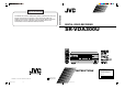
ATTENTION SR-VDA300U JVC EXPRESSLY DISCLAIMS ALL WARRANTIES, EXPRESS OR IMPLIED, AND SHALL NOT BE LIABLE FOR ANY AND ALL DAMAGES, CLAIMS OR LIABILITIES, DIRECT OR INDIRECT, ARISING FROM OR RELATING TO THE USE OF THIS PRODUCT WITH ANY OTHER PRODUCT, DEVICE, COMPONENT, PART OR MATERIAL THAT IS NONCONFORMING OR NON-COMPATIBLE WITH THIS PRODUCT. DIGITAL VIDEO RECORDER SR-VDA300U A.MONITOR POWER VCR TV CABLE/DBS A/B DISPLAY TV/VCR 1 ENTER/OSD 2 .
EN Dear Customer, Thank you for purchasing the JVC digital video recorder. Before use, please read the safety information and precautions contained in the following pages to ensure safe use of your new VCR. CAUTIONS NOTE: CAUTION RISK OF ELECTRIC SHOCK DO NOT OPEN CAUTION: TO REDUCE THE RISK OF ELECTRIC SHOCK. DO NOT REMOVE COVER (OR BACK). NO USER-SERVICEABLE PARTS INSIDE. REFER SERVICING TO QUALIFIED SERVICE PERSONNEL.
EN IMPORTANT PRODUCT SAFETY INSTRUCTIONS Electrical energy can perform many useful functions. But improper use can result in potential electrical shock or fire hazards. This product has been engineered and manufactured to assure your personal safety. In order not to defeat the built-in safeguards, observe the following basic rules for its installation, use and servicing. 3 5. Ventilation Slots and openings in the cabinet are provided for ventilation.
EN USE SERVICING 1. Accessories 1. Servicing To avoid personal injury: • Do not place this product on an unstable cart, stand, tripod, bracket, or table. It may fall, causing serious injury to a child or adult, and serious damage to the product. • Use only with a cart, stand, tripod, bracket, or table recommended by the manufacturer or sold with the product. • Use a mounting accessory recommended by the manufacturer and follow the manufacturer’s instructions for any mounting of the product.
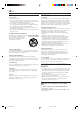
EN 5 Failure to heed the following precautions may result in damage to the recorder, remote control or video cassette. 1. DO NOT place the recorder… … in an environment prone to extreme temperatures or humidity. … in direct sunlight. … in a dusty environment. … in an environment where strong magnetic fields are generated. … on a surface that is unstable or subject to vibration. 2. DO NOT block the recorder’s ventilation openings or holes.
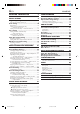
EN CONTENTS INSTALLING YOUR NEW VCR 7 Connections .................................................. 7 INITIAL SETTINGS 9 Plug & Play Setting ....................................... 9 Auto Clock Set/Auto Tuner Set ................................... 9 Clock Setting ............................................... 10 Preparations ............................................................. 10 Setting clock semiautomatically — Semiauto Clock Set ..........................................
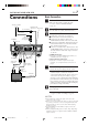
EN INSTALLING YOUR NEW VCR Connections Basic Connection 1 Check contents Antenna or Cable ANTENNA IN (Antenna or cable input) Coaxial Cable Matching Transformer (not supplied) AC Power Cord CABLE BOX Y PB/CB R AUDIO L PR/CR VHF/UHF ANTENNA IN(L-1) IN R AUDIO L(MONO) VIDEO VIDEO REMOTE PAUSE/ AV COMPULINK OUT AC120V 1A TV IN(L-2) S VIDEO OUT Make sure the package contains all of the accessories listed in “SPECIFICATIONS” (墌 pg. 75).
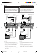
EN INSTALLING YOUR NEW VCR (cont.) S-VIDEO Connection Component Video Connection CONNECT VCR TO TV a– Connect both the RF cable and the AV cables to the TV as explained in step 3 of "Basic Connection" (墌 pg. 7). b– Connect the S-Video cable between the S VIDEO OUT terminal on the rear of the VCR and the S-VIDEO input connector on the TV. CONNECT VCR TO TV a– Connect both the RF cable and the AV cables to the TV as explained in step 3 of "Basic Connection" (墌 pg. 7).
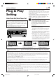
EN INITIAL SETTINGS Plug & Play Setting Auto Clock Set/Auto Tuner Set ATTENTION ● If you use a cable box, Plug & Play will not function; set the clock and tuner channels separately. (墌 pg.10 – 14) ● It takes several minutes for the VCR to complete the Plug & Play setting. ● Do not press any buttons on the front panel or on the Remote while Plug & Play is in progress. TIMER REC LINK STOP/EJECT PLAY POWER PULL-OPEN POWER ASI-IN ASI-REC During Initial Auto Clock Set “Auto” blinks.
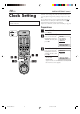
EN INITIAL SETTINGS (cont.) Clock Setting Turn on the VCR and the TV, and select the AV mode on the TV. Perform clock setting only if the clock has not been set correctly by the Plug & Play setting or if you use a cable box. Access the Clock Set screen to perform the Semiauto or Manual Clock Set. Each procedure starts from step 4 after preparation steps below are finished. If you use a cable box, set the clock manually. (墌 pg.
EN Setting clock semiautomatically — Semiauto Clock Set You can change the host channel/D.S.T. /time zone setting manually. First follow steps 1 to 3 on page 10, then go to the following steps. 4 Set Auto Clock to ON Press %fi to move the highlight bar to “AUTO CLOCK”, then press @ # so that “ON” is selected. CLOCK SET UP TIME DATE YEAR 1:00PM 12/24 2003 WED AUTO CLOCK : ON HOST CH : AUTO (CATV) D.S.T.
EN INITIAL SETTINGS (cont.) Setting clock manually — Manual Clock Set VCR TV CABLE/DBS First follow steps 1 to 3 on page 10, then go to the following steps. 1 2 3 4 5 6 7 8 4 Set time Press @ # until the desired time appears, then press fi. 9 0 4–7 45 7 8 CLOCK SET UP TIME DATE YEAR – –:– –AM 1/ 1 2003 AUTO CLOCK : ON HOST CH : AUTO (CATV) D.S.T. : AUTO TIME ZONE : AUTO PRESS (5∞), THEN (2 3) PRESS (MENU) TO END ● Holding @ # changes the time in 30-minute intervals.
EN Tuner Setting Turn on the VCR and the TV, and select the AV mode on the TV. 13 Setting channels automatically — Auto Channel Set Use Auto Channel Set only if channels have not been set correctly by the Plug & Play setting. If you want to add or delete channels, and want to use the ghost reduction function, use Manual Channel Set (墌 pg. 14). 1 Access Main Menu screen 2 Access Tuner Set Up screen Press MENU. Press %fi to move the highlight bar (arrow) to “TUNER SET UP”, then press OK.
EN INITIAL SETTINGS (cont.) 3 Access Manual Channel Set screen Press %fi to move the highlight bar (arrow) to “MANUAL CHANNEL SET”, then press OK.
EN Cable Box Control Setting 15 The following procedure is required if you receive your TV channels through a cable box (descrambler). The Controller allows the VCR to automatically switch the cable box channel during timer recording. The Controller is effective for recording broadcasts that have been programmed using VCR Plus+ (墌 pg. 34) or Express timer programing (墌 pg. 38). Installing Controller Suggested location Place the cable box on top of the VCR.
EN INITIAL SETTINGS (cont.) Turn on the VCR and the TV, and select the AV mode on the TV. Setting cable box output channel & brand After installation, set the cable box output’s channel and its brand correctly; otherwise, the Controller cannot work correctly. 1 Turn on cable box VCR TV CABLE/DBS Select a channel other than channel 9 on your cable box. 1 2 3 4 5 6 7 8 9 7 0 2 Access Main Menu screen on VCR 3 Access Tuner Set Up screen Press MENU.
EN 6 Access Cable Box Brand Set screen 7 Enter cable box brand Press OK. Press the appropriate Number keys to enter the brand code from the list shown to the right, then press OK.
EN INITIAL SETTINGS (cont.) DBS Receiver Control Setting Suggested location Place the DBS (Direct Broadcast Satellite) receiver on top of the VCR. Attach the VCR’s Controller to the top of the VCR with the Controller’s transmitter pointed towards the DBS receiver’s remote sensor. ATTENTION: The Controller can also control a cable box. If both a DBS receiver and a cable box are used, position the Controller so its signal reaches the remote sensors on both the DBS receiver and cable box.
EN Turn on the VCR and the TV, and select the AV mode on the TV. 19 Setting DBS receiver input channel & brand After installation, set the DBS receiver’s input channel and its brand correctly; otherwise, the Controller cannot work correctly. VCR TV CABLE/DBS 1 Turn on DBS receiver Select a channel other than channel 55, 100 or 205 on your DBS receiver. 1 2 3 4 5 6 7 8 9 2 Access Main Menu screen on VCR 3 Access Tuner Set Up screen Press MENU.
EN INITIAL SETTINGS (cont.) 6 Access DBS Receiver Brand Set screen 7 Enter DBS Receiver’s brand Press OK. VCR TV CABLE/DBS 1 2 3 4 5 6 7 8 9 7 0 BRAND JVC (DISH Network) ECHOSTAR (DISH Network) PRIMESTAR SONY (DSS) RCA (DSS) @# 67 OK NOTES: ● The Controller may not work with all types of DBS receiver. ● If your DBS receiver does not respond to the code, you cannot use the Controller to change satellite channels.
EN BASIC PLAYBACK AND RECORDING Basic Playback This VCR can check the tape condition during playback (and recording), and realizes the best possible pictures. ● This recorder can play back tapes that have been recorded in D-VHS (MTP), S-VHS and VHS formats. ● When playing back a tape, this recorder automatically identifies the recording format (D-VHS, S-VHS, or VHS). Turn on the VCR and the TV, and select the AV mode on the TV.
EN BASIC PLAYBACK AND RECORDING (cont.) Basic Playback Features A Press DISPLAY during playback. Each time you press the button, the front display panel shows the time counter, the clock time and the tape remaining time in sequence . Time Counter Turn on the VCR and the TV, and select the AV mode on the TV.
EN C Playing back tape repeatedly — Repeat Playback E 23 Selecting monitor sound — Audio Monitor You can play back a tape repeatedly (50 times). You can select the desired monitor sound. While playing back a tape, press and hold PLAY ( 3 ) for more than 5 seconds. The play indicator ( # ) on the front display panel starts flashing slowly, and a tape will be played back 50 times. To stop playback, press STOP ( 7 ) on the Remote or STOP/EJECT ( 7/0 ) on the front panel.
EN BASIC PLAYBACK AND RECORDING (cont.) F J TIMER STOP/EJECT REC LINC The Next Function Memory “tells” the VCR what to do after rewinding is complete. ● Ensure that the VCR is in stop mode. PLAY POWER DIGITAL 3-D NR S-VIDEO HS/STD/LS3 REC PAUSE 3DNR VIDEO (MONO) L AUDIO R PULL-OPEN S-VHS ET SP/EP CH PRO HD REW FF S-ET MENU Automatic operations after rewinding — Next Function Memory a– For Automatic Playback Start Press REW ( 1 ), then press PLAY ( 3 ) within 2 seconds.
EN H Locating beginning of timer recordings — Instant Review At the press of a button, you can turn on the VCR, rewind the tape and begin to view the most recent timerrecorded program. Press REVIEW on the Remote after ensuring that the VCR is in the timer recording standby mode. ● The VCR turns on, and rewinds to the index code indicating the beginning of the last timer-recorded program, then begins playback automatically.
EN BASIC PLAYBACK AND RECORDING (cont.) Basic Recording This VCR can check the tape condition during recording (and playback), and realizes the best possible pictures. Turn on the VCR and the TV, and select the AV mode on the TV. 3 POWER TIMER STOP/EJECT ( 7/0 ) STOP/EJECT REC LINC DIGITAL 3-D NR VIDEO (MONO) L AUDIO R HS/STD/LS3 REC S-VHS ET SP/EP CH PRO HD REW FF S-ET MENU IN F-1 POWER ASI-IN ASI-REC 2 1 Make sure the record safety tab is intact.
EN 27 Compatibility Of Cassettes And Recording Mode To pause recording Press PAUSE ( 8 ). To resume recording, press PLAY ( 3 ). Recording Mode Cassette To stop recording Press STOP ( 7 ) on the Remote or STOP/EJECT ( 7/0 ) on the front panel. To rewind the tape (when it is not running) Press REW ( 1 ). To fast-forward the tape (when it is not running) Press FF ( ¡ ). VHS D-VHS Yes Yes S-VHS Yes Yes VHS Yes* Yes * To record on the VHS cassette with S-VHS quality, use the SVHS ET function.
EN BASIC PLAYBACK AND RECORDING (cont.) Basic Recording Features A Press DISPLAY during recording or recording pause. Each time you press the button, the front display panel shows the time counter, channel number, clock time, and the tape remaining time in sequence. Time Counter Turn on the VCR and the TV, and select the AV mode on the TV.
EN one program while C Watching recording another 1 Engage TV mode 2 During recording... ● Change the TV’s input mode from AV to TV. Select channel for viewing Select the channel you want to watch, on the TV. D Showing on-screen display E Display VCR status on TV screen During recording or recording pause, press SAP STEREO OSD on the Remote. REC PAUSE HI-FI All indications THU 12:00 AM ] corresponding to the STD 33 INDEX-9 – 1:23:45 current VCR status are B E displayed for 5 seconds.
EN BASIC PLAYBACK AND RECORDING (cont.) Other useful functions for recording Accidental erasure prevention You can also use the following functions for recording. To prevent accidental recording on a recorded cassette, remove its record safety tab. To record on it later, cover the hole with adhesive tape.
EN SPECIAL EFFECT PLAYBACK Special Effect Playback Turn on the VCR and the TV, and select the AV mode on the TV. ATTENTION When playing back a tape recorded in PRO HD (based on D-VHS) format, the JOG dial and SHUTTLE ring do not work. VCR TV CABLE/DBS 31 With this VCR, you can enjoy special effect playback such as high-speed search, variable-speed search, and still playback and so on.
EN SPECIAL EFFECT PLAYBACK (cont.) B To use the JOG dial/SHUTTLE ring on the Remote, first press JOG/SHUTTLE on the remote control so that the button lights up. Still Viewing still picture — Still Picture Playback Press PAUSE ( 8 ) during normal playback. Playback is freezed and a still picture appears. Slow motio n ve rs e Re low s y NOTE: Pl a To obtain a noiseless still picture, it may be necessary to adjust tracking in slow motion playback before starting still picture playback.
EN D 2 4 5 6 7 8 9 3 0 CH +/– PLAY ( 3 ) PAUSE ( 8 ) D D Viewing slow motion picture — Slow Motion Playback (S-VHS/VHS only) During normal playback or still picture playback: Turn the SHUTTLE ring slowly to the right (forward slow motion) or to the left (reverse slow motion) so that slow motion playback starts.When you release the ring, a still picture appears. ● Holding PAUSE ( 8 ) for more than 2 seconds also starts forward slow motion playback.
EN TIMER RECORDING VCR Plus+ Timer Programing ® Turn on the VCR and the TV, and select the AV mode on the TV. Timer recording allows you to program the VCR to automatically record a broadcast at some future time. Up to 24 timer recording programs can be made using VCR Plus+ timer programing or Express timer programing method (墌 pg. 38) as far as a year in advance.
EN 4 Input receiving channel number The guide channel GUIDE CHANNEL SET UP number, which is GUIDE CH 12 assigned to the TV or VCR CH – – – cable station for the PlusCode number that PRESS NUMBER KEY (0–9) you entered in step 3, OR (2 3), THEN (OK) PRESS (PROG.) TO END will appear automatically on the Guide Channel Set Up screen. Press the Number keys (or @ #) to input the number of the channel on which the broadcast for the PlusCode number is received on the VCR or cable box, then press OK.
EN TIMER RECORDING (cont.) Changing VCR Plus+® Setting IMPORTANT If you have moved to a different area or if a broadcasting station’s channel number has been changed, the wrong VCR CH or CABLE CH number will be displayed on the Program screen (墌 step 5 on page 35). When this happens, perform the following steps to set the correct guide channel number for that station. Turn on the VCR and the TV, and select the AV mode on the TV.
EN 1 Access Main Menu screen 2 Access Tuner Set Up screen Press MENU. Press %fi to move the highlight bar (arrow) to “TUNER SET UP”, then press OK. MAIN MENU Password SET UP FUNCTION SET UP 3 TUNER SET UP INITIAL SET UP PRESS (5∞), THEN (OK) PRESS (MENU) TO END 3 Access Guide Channel Set screen Press %fi to move the highlight bar (arrow) to “GUIDE CHANNEL SET”, then press OK.
EN TIMER RECORDING (cont.) Express Timer Programing Turn on the VCR and the TV, and select the AV mode on the TV. You can directly program the VCR’s timer to record up to 24 broadcasts, as far as a year in advance. Remember, the clock must be set before you can program the timer (墌 pg. 10). 1 Load a cassette Make sure the record safety tab is intact. If not, cover the hole with adhesive tape, then load it into the VCR. ● The VCR turns on, and the counter is reset, automatically.
EN 8 Set tape speed 39 NOTES: Press HS/STD/LS3/SP/LP ( speed. ) to set the tape 9 Return to normal screen Press PROG. or OK. “PROGRAM COMPLETED” appears on the screen for about 5 seconds, then normal screen appears. 0 Engage timer recording standby mode Press TIMER. The VCR turns off automatically and “‰” is displayed on the front display panel. To timer-record daily (Monday–Friday) or weekly serials Press DAILY (M-F) (number “8”) or WEEKLY (number “9”) anytime during steps 3 through 8.
EN TIMER RECORDING (cont.) B Turn on the VCR and the TV, and select the AV mode on the TV. 1 Canceling or changing program settings Access Program screen Repeat steps 1 to 3 in the left column. 2 VCR TV CABLE/DBS A B B 1 2 3 4 5 6 7 8 9 –2 A B 0 A B –2 To cancel a program, press CANCEL. –1 –1 B –4 START STOP DATE 8:00PM 10:00PM 12/24/03 CH WED CATV 12 STD (SP) PRESS (CANCEL) TO CANCEL PRESS (OK) TO PROG. LIST PRESS (P.
EN ATTENTION If there is a conflict in the timer schedule and one program overlaps with another, only the parts shown below in gray will be recorded. Pattern 1: The program with the lower program number will be recorded. 10:00 11:00 Program 1 Program 2 Pattern 2: 10:00 10:00 Program 1 Not recorded The program starting earlier will be recorded.
EN PRO HD SYSTEM PRO HD System Features ● This digital video recorder is a professional deck designed for the PRO HD system. TIMER REC LINK STOP/EJECT ● This system can record the MPEG2-TS signal on the D-VHS tape via the interface of DVB-ASI. PLAY POWER PULL-OPEN POWER ASI-IN ASI-REC ● This system is impossible to record by a D-VHS format. SR-VDA300U ● In the case of recording, the password can be set.
EN Connection And Preparation 43 Connection 1 Check contents Make sure the package contains all of the accessories listed in “SPECIFICATIONS” ( pg. 75). 2 Situate VCR Place the VCR on a stable, horizontal surface. Antenna or Cable ANTENNA IN (Antenna or cable input) Coaxial Cable 3 Connect VCR to TV The following connections are required. Flat Feeder 1 Disconnect the TV antenna from the TV. 2 Connect the TV antenna cable to the ANTENNA IN terminal on the rear of the VCR.
EN PRO HD SYSTEM (cont.) Preparations 1 1 Press POWER (upper left side) TIMER REC LINC STOP/EJECT PLAY POWER DIGITAL 3-D NR S-VIDEO HS/STD/LS3 REC PAUSE 3DNR VIDEO (MONO) L AUDIO R PULL-OPEN S-VHS ET SP/EP CH PRO HD REW FF S-ET IN F-1 MENU POWER ASI-IN ASI-REC 2 Select input location on this VCR ASI-REC indicator 2 3 ASI-IN indicator On the front panel or Remote : Press CH +/– to select an “I-” channel. Proceed to the next step after 5 seconds.
EN Recording This VCR can check the tape condition during recording (and playback), and realizes the best possible pictures. Turn on the VCR and the TV, and select the AV mode on the TV. STOP/EJECT ( 7/0 ) POWER TIMER REC LINC 45 STOP/EJECT In the case of recording, the password can be set. When you set up a password, please carry out before recording. Please refer to next page for the procedure of setting the password.
EN PRO HD SYSTEM (cont.) Password SET UP You can use the password setting function on the Password Set Up screen by following the procedure described below. 1 Access Main Menu screen Press MENU. Turn on the VCR and the TV, and select the AV mode on the TV. 2 Access Password Set Up screen Press %fi to move the highlight bar (arrow) to “Password SET UP” then press OK.
EN This VCR can check the tape condition during playback (and recording), and realizes the best possible pictures. Playback Turn on the VCR and the TV, and select the AV mode on the TV.
EN OTHER USEFUL FUNCTIONS Useful Function Settings Turn on the VCR and the TV, and select the AV mode on the TV. You can use the other useful function settings on the Function Set Up screens by following the procedure described below. ● For the functions you can set on the Function Set Up screen, see pages 49 to 53. 1 Access Main Menu screen 2 Access Function Set Up screen Press MENU. Press %fi to move the highlight bar (arrow) to “FUNCTION SET UP”, then press OK.
EN Video settings [VIDEO (VHS)] 䡵 V, CALIBRATION (S-VHS/VHS only) 49 * The default setting is bold in the table below. When this function is set to “ON”, this VCR checks the condition of the tape in use during playback and recording, and compensates to provide the highest-possible pictures. This takes place whenever you play back a tape or start recording after inserting a tape.
EN OTHER USEFUL FUNCTIONS (cont.) Audio settings [AUDIO] 䡵 OPTICAL OUT * The default setting is bold in the table below. This VCR can send the Dolby Digital bitstream or PCM Audio to external devices. When you play back a tape including the Dolby Digital bitstream, and if you have a device equipped with Dolby Digital decoder, set this function to “Dolby D”. If not, set this function to “2CH-PCM”. The digital audio is output only when you play back a tape recorded in D-VHS format.
EN Input/Output settings [IN/OUT] 䡵 TV OUTPUT 1 51 * The default setting is bold in the table below. Select the apppropriate mode when playing back a D-VHS tape containing a recording of an HD (High Definition) signal: 720to1080 NO CONV. ALLto480i 720to1080: 720p is up-converted to 1080i and output to the TV. 1080i, 480p, and 480i image formats are output to the TV without being converted. Select this when the 720p image played back is distorted. NO CONV.
EN OTHER USEFUL FUNCTIONS (cont.) Additional settings [ADDTL] 䡵 AUTO SP = EP TIMER (S-VHS/VHS only) * The default setting is bold in the table below. When this function is set to “ON”, the VCR automatically switches to EP mode to allow complete recording if there is not enough tape to record the entire program while timer-recording in SP mode. For Example . . .
EN 53 * The default setting is bold in the table below. 䡵 S-VHS MODE ON OFF You can determine which recording mode — either S-VHS mode or VHS mode — is used for recording on D-VHS and S-VHS tapes. When this function is set to “ON”, you can record on D-VHS and S-VHS tapes with S-VHS picture quality. When this function is set to “OFF”, you can record on D-VHS and S-VHS tapes with VHS picture quality. NOTES: ● To record in S-VHS/VHS mode on D-VHS tape, press PRO HD to turn off the D-VHS indicator.
EN OTHER USEFUL FUNCTIONS (cont.) Satellite Auto Recording 1 Set timer program on DBS receiver • For timer programing method, refer to the manual supplied with the DBS receiver. This function allows you to automatically record a satellite program which is timer-programed on your DBS receiver. 2 Load a cassette 3 Set tape speed Preparation: Connect a DBS receiver to the AUDIO/ VIDEO IN or S VIDEO IN (L-1) connectors* on the rear; otherwise, you cannot use this function.
EN JLIP ID Number Setting 55 The JLIP (Joint Level Interface Protocol) terminal is used to connect the VCR to a personal computer or similar device. By connecting through the JLIP terminals, you can control the VCR during editing and certain other operations, from the connected personal computer or similar device. When connecting this VCR to another device using the JLIP terminals, each device must have a different JLIP ID number.
EN EDITING Edit From Camcorder VCR TV CABLE/DBS This VCR (for recording) TIMER STOP/EJECT REC LINC PLAY POWER DIGITAL 3-D NR S-VIDEO VIDEO (MONO) L AUDIO R HS/STD/LS3 REC 1 2 4 5 6 7 8 9 PAUSE 0 3DNR S-VHS ET SP/EP CH PRO HD REW 3 FF S-ET MENU IN F-1 POWER ASI-IN ASI-REC To rear panel REMOTE PAUSE/ AV COMPULINK connector To AUDIO Input Audio cable (supplied) 9 8 4–6 47 To S-VIDEO Input 3 3 4–6 Mini-plug cable (not supplied) (JVC camcorder only) S-video cable (sup
EN You can use a camcorder as the playback VCR and your VCR as the recording VCR. 1 S-VHS/VHS connection Connect an audio cable between the camcorder’s audio output connectors and your VCR’s audio input connectors. ● When the JVC camcorder is equipped with the Master Edit Control, you can control the VCR from the camcorder. Connect the mini-plug cable (not supplied with this VCR) as illustrated on page 56.
EN EDITING (cont.) Edit To Or From Another VCR/Other Devices You can use your VCR as the playback or recording VCR. ● Refer also to the other VCR’s instruction manual for connection and its operations. This VCR supports the copy protection technologies of DTLA (Digital Transmission Licensing Administrator). These technologies are admitted by DTLA (Digital Transmission Licensing Administrator).
EN 59 2 Load cassettes Insert the playback cassette into the playback VCR and the cassette to be recorded on into the recording VCR. VCR TV CABLE/DBS 3 Select input mode on recording VCR Select the correct external input on the other VCR. 1 2 3 4 5 6 7 8 9 3 3 0 ● On this VCR (when using this VCR as the recording VCR); L-1 or L-2 — when connecting the other VCR to the audio/video input connectors or the rear panel.
EN MULTI-BRAND REMOTE CONTROL TV Brand Setting 2 This Remote can control some functions of remote controllable TVs listed below. Without setting, you can control a JVC TV. 1 Turn on the TV Turn on the TV using the Power button on the TV or its Remote. 3 –1 3 POWER ENTER VCR TV CABLE/DBS TV/VCR 1 2 3 4 5 6 3 –2 7 8 9 Number 0 2 Set remote operation mode 3 Set TV brand code Set the VCR/TV/CABLE/DBS selector to “TV”. Follow the example shown below. 1 Press and hold POWER.
EN Cable Box Brand Setting 61 This Remote can control some functions of the cable boxes listed below. Some cable box brands have more than one code. If your cable box does not function with a specified code, try other codes. 1 Turn on the cable box Turn on the cable box using the Power button on the cable box or its Remote. 2 3 –1 3 POWER ENTER VCR TV CABLE/DBS 1 2 3 4 5 6 3 –2 7 8 9 Number 2 Set remote operation mode Set the VCR/TV/CABLE/DBS selector to “CABLE/ DBS”.
EN MULTI-BRAND REMOTE CONTROL (cont.) DBS Receiver Brand Setting This Remote can control some functions of the DBS (Direct Broadcast Satellite) receivers listed below. 1 Turn on the DBS receiver Turn on the DBS receiver using the Power button on the DBS receiver or its Remote. 2 Set remote operation mode Set the VCR/TV/CABLE/DBS selector to “CABLE/ DBS”. 2 3 –1 3 POWER VCR TV CABLE/DBS 3 Enter DBS receiver brand code Follow the example shown below. 1 Press and hold POWER.
EN Changing Remote Control Code 2 63 This Remote is capable of transmitting two control codes; one set to respond to A code control signals and another set to respond to B code control signals. This Remote control is preset to send A code signals because your VCR is initially set to respond to A code signals. You can easily modify your VCR and the Remote to respond to B code signals. When using two JVC VCRs, set two VCRs and their Remotes to different codes, so that you can operate these VCRs separately.
EN TROUBLESHOOTING Before requesting service, use this chart and see if you can repair the trouble yourself. Small problems are often easily corrected, and this can save you the trouble of sending your VCR off for repair. POWER SYMPTOM POSSIBLE CAUSE CORRECTIVE ACTION 1. The power will not come on. ● The AC power cord is disconnected. Connect the AC power cord. 2. The clock works, but the VCR’s power will not come on.
EN 65 TIMER RECORDING POSSIBLE CAUSE SYMPTOM 1. Timer recording will not work. ● The clock and/or the timer have been set incorrectly. ● The timer is not engaged. ● The VCR has not been set up properly. CORRECTIVE ACTION Set the clock and/or timer correctly. Press TIMER and check to make sure that ‰ appears on the front display panel. Re-perform the set-up procedures. Make sure you have compensated for guide channel and VCR or cable box channel number mismatches (墌 pg. 36). 2.
EN TROUBLESHOOTING (cont.) OTHER PROBLEMS SYMPTOM POSSIBLE CAUSE 1. When scanning channels, some of them are skipped over. ● Those channels have been preset to be skipped. If you need the skipped channels, restore them (墌 pg. 14). 2. The channel cannot be changed. ● Recording is in progress. Press PAUSE ( 8 ) to pause the recording, change channels, then press PLAY ( 3 ) to resume recording. 3. The Remote will not operate your TV or cable box or DBS receiver.
EN 67 Error Codes and Messages Some error codes and messages may appear on the TV screen when operating the VCR. Refer to the chart below for the solution. CODE MESSAGE DESCRIPTION 102 REC PROHIBITED ● An attempt was made to make a PRO HD recording of a program for which only the analog information is copy protected. ● While making a PRO HD recording of a program, a signal in which only the analog information is copy protected was input to this VCR.
EN TROUBLESHOOTING (cont.) Questions and answers PLAYBACK RECORDING Q. What happens if the tape reaches its end during playback or search? A. The VCR automatically rewinds it to the beginning. ............................................ Q. Can the VCR indefinitely remain in still mode? A. No. It stops automatically after 5 minutes to protect the heads. ............................................ Q.
EN INDEX 69 List of terms This guide serves as a quick way to locate frequently used terms and on-screen display names.
EN INDEX (cont.) Front panel 12 3 4 TIMER 5 6 789 0 ! STOP/EJECT REC LINC PLAY POWER DIGITAL 3-D NR S-VIDEO HS/STD/LS3 REC PAUSE 3DNR VIDEO (MONO) L AUDIO R S-VHS ET SP/EP CH PRO HD REW FF S-ET MENU IN F-1 POWER ASI-IN ASI-REC @ #$ 1 POWER button : 墌 pg. 21, 27 2 Remote sensor 3 TIMER ‰ button : 墌 pg. 35, 39, 40 4 REC LINK button : 墌 pg. 54 5 DIGITAL 3-DNR button and lamp : 墌 pg. 25 6 Cassette loading slot 7 HS/STD/LS3/SP/EP button : 墌 pg.
EN 71 Rear panel 1 3 2 5 4 6 7 CABLE BOX Y PB/CB R AUDIO L PR/CR 8 VHF/UHF ANTENNA IN(L-1) IN R AUDIO L(MONO) VIDEO VIDEO REMOTE PAUSE/ AV COMPULINK OUT AC120V 1A S VIDEO OUT TV IN(L-2) S VIDEO OUT IN G DVB-ASI IN SYNC POL – + 9 0 ! @ 1 AC power cord : 墌 pg. 7 2 Cooling fan ● This prevents the temperature from rising inside the VCR. Do not remove it. ● Install the VCR so as not to block the area around the cooling fan. 3 Component video output connectors : 墌 pg.
EN INDEX (cont.) Front display panel 1 2 3 4 5 6 7 S-VHS ET 0dB NORM -15 +8 8 9 0 1 Recording speed indicator : 墌 pg. 26 Timer programming indicator (“Pro” appears when PROG. or PROG. CHECK button is pressed. “Err” appears when the guide channel error occurs.) : 墌 pg. 40 2 Audio Monitor Indicators : 墌 pg. 23 3 Symbolic Mode Indicators : 墌 pg. 23 PLAY: FF/REW VARIABLE SHUTTLE SEARCH: STILL: SLOW: RECORD: RECORD PAUSE: 4 Timer mode indicator : 墌 pg. 35, 39 5 D-VHS indicator : 墌 pg.
EN 73 On-screen display % 1 2 3 4 5 6 JVC SR-DVA300US 1 Brand name of the device connected to the DVB-ASI connector 2 Model name of the device connected to the DVB-ASI connector 3 Clock time 4 Tape speed indication 5 Time counter (When “COUNT“ appears) : 墌 pg. 22, 28 Tape remaining time (When “REMAIN“ appears) : 墌 pg. 22, 28 6 Tape position indicator : 墌 pg.
EN INDEX (cont.) Remote 1 2 3 4 5 6 7 8 9 0 ! A.MONITOR POWER VCR TV CABLE/DBS TV/VCR A/B 1 DISPLAY ENTER/OSD 2 .,? 3 ABC DEF 2 4 5 6 GHI JKL MNO DBS DAILY(M-F) WEEKLY 8 7 PQRS TUV C. RESET AUX CANCEL 0 START STOP 9 WXYZ 4 TIMER DATE CH EXPRESS PROGRAMMING 1 HS/STD/LS3 SP/EP PROG. BACK REW PROG.
EN SPECIFICATIONS GENERAL Power requirement Power consumption Power on Power off Temperature Operating Storage Humidity Operating Operating position Dimensions (W x H x D) TUNER : AC 120 V`, 60 Hz : 61 W : 18 W : 5°C to 40°C (41°F to 104°F) : –20°C to 60°C (–4°F to140°F) : 35% to 80% : Horizontal only : 435 mm x 146 mm x 376 mm (17-3/16" x 5-3/4" x 14-13/16") : 9.2 kg (20.3 lbs) Weight Maximum recording time PRO HD (HS) : 210 min. with DF-420 video cassette PRO HD (STD) : 420 min.
EN FOR SERVICING (Only in U.S.A.) HOW TO LOCATE YOUR JVC SERVICE CENTER TOLL FREE: 1-800-537-5722 http://www.jvc.com Dear customer, In order to receive the most satisfaction from your purchase, please read the instruction booklet before operating the unit. In the event that repair is necessary, or for the address nearest your location within the Continental United States, please call 1-800-537-5722 for your nearest authorized servicer or visit our website at www.JVC.com.
EN WARRANTY (Only in U.S.A.) LIMITED WARRANTY 77 CONSUMER VIDEO 1-90 JVC COMPANY OF AMERICA warrants this product and all parts thereof, except as set forth below ONLY TO THE ORIGINAL PURCHASER AT RETAIL to be FREE FROM DEFECTIVE MATERIALS AND WORKMANSHIP from the date of original retail purchase for the period as shown below.
EN VDA300U-EN64-79 MEMO 78 03.7.
EN VDA300U-EN64-79 79 03.7.
ATTENTION SR-VDA300U JVC EXPRESSLY DISCLAIMS ALL WARRANTIES, EXPRESS OR IMPLIED, AND SHALL NOT BE LIABLE FOR ANY AND ALL DAMAGES, CLAIMS OR LIABILITIES, DIRECT OR INDIRECT, ARISING FROM OR RELATING TO THE USE OF THIS PRODUCT WITH ANY OTHER PRODUCT, DEVICE, COMPONENT, PART OR MATERIAL THAT IS NONCONFORMING OR NON-COMPATIBLE WITH THIS PRODUCT. DIGITAL VIDEO RECORDER SR-VDA300U A.MONITOR POWER VCR TV CABLE/DBS A/B DISPLAY TV/VCR 1 ENTER/OSD 2 .