COLOR VIDEO CAMERA COLOR VIDEO CAMERA TK-C1530U/E TK-C1531EG TK-C925U/E TK-C926EG INSTRUCTIONS : Only for TK-C1530U/E and TK-C1531EG © 2006 Victor Company of Japan, Limited TK-C1530U/E, TK-C1531EG : LST0459-001B TK-C925U/E, TK-C926EG : LST0450-001B
FOR USA These are general IMPORTANT SAFEGUARDS and certain items may not apply to all appliances. IMPORTANT SAFEGUARDS 1. Read all of these instructions. 2. Save these instructions for later use. 3. All warnings on the product and in the operating instructions should be 4. 5. 6. 7. 8. adhered to. Unplug this appliance system from the wall outlet before cleaning. Do not use liquid cleaners or aerosol cleaners. Use a damp cloth for cleaning.
Introduction INFORMATION FOR USA Safety Precautions FOR USA AND CANADA CAUTION RISK OF ELECTRIC SHOCK DO NOT OPEN CAUTION : TO REDUCE THE RISK OF ELECTRIC SHOCK. DO NOT REMOVE COVER (OR BACK). NO USER-SERVICEABLE PARTS INSIDE.REFER SERVICING TO QUALIFIED SERVICE PERSONNEL.
Introduction Safety Precautions (continued) Information for Users on Disposal of Old Equipment [European Union] Attention: This symbol is only valid in the European Union. This symbol indicates that the electrical and electronic equipment should not be disposed as general household waste at its end-oflife.
Introduction Thank you for purchasing this product. (These instructions are for TK-C1530U/E and TK-C1531EG.) Before beginning to operate this unit, please read the instruction manual carefully in order to make sure that the best possible performance is obtained.
Introduction Operating Precautions Storage and Location of Use 䢇 This camera has been designed for indoor use. When you use it outdoors, be sure to use a housing or the like. 䢇 Do not install or use the camera in the following places. ● In a place exposed to rain or moisture. ● In a place with vapor or oil, for example in a kitchen. ● When the ambient temperature rises above or falls below the acceptable range (from -10 I to 50 I) ● In a place at which corrosive gases are emitted.
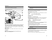
Introduction Note: ● Do not use a screw that is longer than the specified length. It may damage the internal parts. Name of Parts and their Functions Front/Bottom/Side panel A D [IRIS] Iris Terminal J I B H E [VIDEO,DC] Iris Selector Switch This should be set according to the type of lens if an automatic iris control lens is used. VIDEO : In case of lens with EE amp built-in DC : In case of lens without EE amp built-in (Default setting: DC) (A Pg.
Introduction : Only for TK-C1530U/E and TK-C1531EG Name of Parts and their Functions (continued) K [AC24V,DC12V] Power input terminal To connect to AC 24 V or DC 12 V power supply. (A Pg. 22) Back panel L [TX+ A ,TX- B ,RX+ C ,RX- D ] Control signal connection terminal 䡵 TK-C1530/TK-C925 Terminal for inputting or outputting signals with electrical characteristics conforming to the EIATIA RS-422A or RS-485 standard.
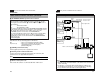
: Only for TK-C1530U/E and TK-C1531EG Introduction Name of Parts and their Functions (continued) : Only for TK-C1530U/E and TK-C1531EG Setup System Example Q [RX TERM-OFF,ON/INT,LL] Function Selector Switch R [POWER] Power indicator lamp H Av Pk L Camera 1 ALC LEVEL Power Cable DIGITAL TK-C1530U/E : AC24 V or DC12 V TK-C1531EG : AC220 V-240V Control Signal Cable Video Signal Cable ALC LEVEL Camera 2 Av Pk L H MACHINE ID : 1 (MENU screen) RX TERM : OFF (Switch) DIGITAL H Camera 8 ALC LEVEL
: Only for TK-C1530U/E and TK-C1531EG Setup System Example (continued) Flow for Connection/Settings Follow the procedures below to connect/set this unit. Turn off the power of devices to be used before connecting the cables. Precautions when using RM-P2580E: When operating a system using the RM-P2580E, several cameras (up to 16) can be connected and used on one control signal cable. Consequently, an incorrect switch setting on just a single camera will cause the entire system to work incorrectly.
Setup 1. Mounting the lens Check the mounting method of the lens before mounting ● This camera is set to CS-mount lens before shipment. To use a C-mount lens, loosen the back focus fastening screw with a screwdriver, turn the back focus adjustment ring with your finger or the screwdriver and change the mounting method. ● For the dimension (a) of the lens mounting section as illustrated in the diagram, use the value that is shown in the table below.
: Only for TK-C1530U/E and TK-C1531EG Setup : Only for TK-C1530U/E and TK-C1531EG Note: ● If thin cables are used, the resistance of the cables will be high and a significant voltage drop will occur when the camera is at its maximum power consumption. Either use a thick cable with low resistance or place the power supply near to the camera and shorten the length of the cable to restrict the voltage drop at the rated current of camera to below 10 %.
Setup Connecting the back panel (continued) Connecting alarm input/output terminal 䡵 Alarm input terminal Connect infrared sensor, door sensor, metal sensor or sensor of manual switch and the like. ● To prevent noise from entering the internal circuit, supply non-voltage setting signal. ● Do not supply voltage. ● Can be set via menu whether to set to alarm when the contact is short (MAKE), or when the contact is open (BREAK). (A Pg. 39) ● Supply such that the alarm signal continues for more than 200 ms.
Setup 1. Mounting the camera (continued) Mounting the camera-mounting bracket on top of the camera The camera-mounting bracket is originally mounted at the bottom of the camera before shipment but it can also be mounted on top of the camera. 1 2. 3. Remove the camera-mounting bracket fastening screws (x2). The camera-mounting bracket is removed from the camera.
Setup Adjusting the back focus This camera is adjusted to a optimum wide range for CS-mount lens before shipment but readjustment is required when using zoom lens or C-mount lens or when the lens focus ring is out of focus. Use the following methods to adjust the back focus. With a fixed-focus lens If the focus cannot be adjusted correctly with the lens focus ring, adjust the back focus as follows. 1. 2. Back focus adjustment ring 3. 4. 5.
Setup 䢇 LEVEL adjustment Adjusting the lens After the connection is complete, turn on the camera, display an image on the monitor and check the video image. In the case of an automatic iris control lens, the camera has been factoryadjusted to the best position, but it may need to be adjusted according to the condition of the object or the lens combination. If the image is unnatural, adjust it. ● Also read the instruction manual of the lens.
Setup 1. Adjusting the auto white balance Each light source has its own color temperature. Therefore, when the main light source lighting an object is changed, press the SET button for a while and adjust the white balance again. 2. 3. CLASS 2 ONLY(U TYPE) ISOLATED POWER ONLY(E TYPE) SEE INSTRUCTION MANUAL Place a white object at the center of the screen, under the same lighting condition as the object to be shot and zoom in to fill the screen with white. Press the SET button for approx. one second.
36 (A Pg. 38) (A Pg. 49) FACTORY SETTINGS (A Pg. 53) MAINTENANCE (A Pg. 52) COMMUNICATION MODE MAX GAIN FIX GAIN GAIN No.1 No.2 No.3 No.4 CANCEL EXECUTE This will not be displayed when the menu is activated using RM-P2580 and external communication. Use the camera switch to set this item. MASK EDIT When AONB is selected CANCEL CLEAR(WITHOUT TITLE) CLEAR(ALL) CCD SPOT SCAN TYPE STYLE MACHINE ID MASK MASK MASK MASK V.PHASE MONITOR TYPE S.E.C.
: Only for TK-C1530U/E and TK-C1531EG Setting Item AUX FUNCTION screen Item AUX MODE INPUT POLARITY Functions and settings This item sets the signal input or output of the AUX terminal. B&W OUT : A signal is output when the camera switches to B&W or Color mode. SCENE IN : Depending on the input signal of the AUX terminal, the camera can switch between scene files (A, B only). IR IN : Depending on the input signal of the AUX terminal, the camera can switch between B&W and Color mode.
Setting TITLE/VIDEO screen (continued) Item SHUTTER Item W.BALANCE AWC Functions and settings (continued) AWC SET: The Auto White Control (automatic white balance adjustment) mode adjusts the white balance automatically.
Setting TITLE/VIDEO screen (continued) Item GAIN Item GAIN Functions and settings This item sets the gain. (continued) MAX GAIN Memo: ● If the gain is increased, the screen appears grainy in a dark place. MODE Select the gain adjustment mode. Sensitivity increases electronically for an object with low illumination. AGC (Automatic Gain Control) : This automatically adjusts the electronic gain according to the illumination of the object.
: Only for TK-C1530U/E and TK-C1531EG Setting Item TITLE/VIDEO screen (continued) “COLOR” display differs depending on the model. “COLOR” is displayed for TK-C1530U/TK-C925U and “COLOUR” is displayed for TK-C1530E/TK-C1531EG/TK-C925E/TK-C926EG. From this point onwards, “COLOR” will be used for indication. Item B&W/COLOR (TK-C1530U/ TK-C925U) B&W/COLOUR (TK-C1530E/ TK-C1531EG/ TK-C925E/ TK-C926EG) MODE Functions and settings This item sets the mode switching of B&W and Color.
: Only for TK-C1530U/E and TK-C1531EG TITLE/VIDEO screen (continued) Item B&W/COLOR Item B&W/COLOR AUTO LEVEL Functions and settings (continued) When the MODE item is set to AAUTOB, this function sets the signal level of the object where the camera will switch to B&W mode. LOW : Switches to B&W mode when the signal level of the object indicates low illumination. NORMAL: Switches to B&W mode when the signal level of the object indicates normal illumination.
: Only for TK-C1530U/E and TK-C1531EG Setting DISPLAY screen TITLE/VIDEO screen (continued) Item Item BLC MODE Functions and settings Sets the backlight compensation function. Set this item when there is a bright light source in the background of the object and the object becomes dark in the automatic iris function. Set such that unnecessary light source is outside the photometry area. OFF : No backlight compensation. AREA1 to AREA4 : Refer to the diagram below to set the item.
: Only for TK-C1530U/E and TK-C1531EG Setting COMMUNICATION screen PRIVATE MASK screen Item MASK No.1 MASK No.2 MASK No.3 MASK No.4 : Only for TK-C1530U/E and TK-C1531EG Functions and settings This function masks parts of an image in gray display such that the masked parts will not be shown on the screen. Select AONB and press the SET button. The MASK EDIT screen appears and mask settings can be made. APrivate mask settingB (A Pg. 62) ON : Private mask is enabled. OFF : Private mask does not display.
Setting MAINTENANCE screen FACTORY SETTING screen White spots may appear on the screen due to changes in properties with time. This is a general characteristic of CCDs. This camera has a built-in white spot compensation function to reduce these white spots. Item CCD SPOT SCAN Functions and settings : No white spot compensation. The screen returns to the main menu. EXECUTE : Starts CCD spot detection. Item Functions and settings CANCEL Does not return to the default setting.
Detailed setting 2. Camera title setting A title can be selected for each camera. (Maximum 24 characters) CLASS 2 ONLY(U TYPE) ISOLATED POWER ONLY(E TYPE) SEE INSTRUCTION MANUAL 4. POWER + 1 2 INT DC12V d AC24V H LL RX TERM-OFF ON MENU button 5. MENU SET VIDEO OUT SELECTOR 3. SET button and SELECTOR switch Press the SELECTOR switch up, down, left or right (J, K, H, I) and select a character from the character area. The selected character is displayed flashing on and off.
: Only for TK-C1530U/E and TK-C1531EG Detailed setting : Only for TK-C1530U/E and TK-C1531EG 䡵 Set the B&W/COLOR item to AUTO Output of B&W/Color switching signal It is possible to output B&W/Color switching signal from the AUX terminal on the back of this camera. B&W/Color switching signal is output by setting both the AUX MODE and B&W/COLOR items. 䡵 Set the AUX MODE item to AB&W OUTB 1. Select the item AUX FUNCTION on the main menu screen and press the SET button. The AUX FUNCTION screen is displayed.
Detailed setting : Only for TK-C1530U/E and TK-C1531EG Control by B&W/Color switching signal from external You can use the switching signal from an external control device to link the B&W/Color switching or near-infrared illumination of this camera. Consult your nearby JVC’s dealer on the connecting devices. Example) AUX MODE : IR IN INPUT POLARITY : In the case of MAKE (A Pg. 38) B&W Color CLASS 2 ONLY(U TYPE) ISOLATED POWER ONLY(E TYPE) - 1 2 SEE INSTRUCTION MANUAL INT DC12V d AC24V H 1. 2.
: Only for TK-C1530U/E and TK-C1531EG Detailed setting : Only for TK-C1530U/E and TK-C1531EG 䡵 Setting a mask area 1. Private mask setting Perform private mask setting to mask images that you do not want to be shown on the screen in gray. You can set 4 locations in the display screen. 䡵 Selection of mask number 1. 2. 3. 2. Select the item PRIVATE MASK on the main menu screen and press the SET button. The PRIVATE MASK screen is displayed. Select a mask number with SELECTOR switch (J, K).
: Only for TK-C1530U/E and TK-C1531EG Detailed setting Scene file function This camera has 4 types of scene files (SCENE A to SCENE D) for detailed video settings according to the shooting condition of the object. Scene files can be switched using AUX terminal input (SCENE A, SCENE B only) or external communication (SCENE A to SCENE D). 䡵 Switching day/night video settings with the scene file function Example) AUX MODE INPUT POLARITY : SCENE IN : In the case of MAKE (A Pg.
Others Specifications 䡵 Camera Signaling method TK-C1530U/TK-C925U : NTSC TK-C1530E/TK-C1531EG/TK-C925E/TK-C926EG : PAL Image pickup device : 1/3 type IT CCD Color imaging method : Single color-difference line sequential system, 2:1 interlace Imaging area : 4.8 mm (H) ⳯ 3.
Others TK-C1531EG Specifications (continued) 䡵 Dimensions [Unit: mm] TK-C1530U/E 65 115 R5 4- 115 5 -R 4 7,5 7,5 35 35 55 55 65 126 U1-32 126 U1-32 42 42 1/4-20UNC 1/4-20UNC 30 30 T Specifications and appearance of this camera and related products are subject to change for improvements without notice.