TK-C1530_EN.book Page 1 Friday, August 24, 2007 9:29 AM COLOR VIDEO CAMERA TK-C1530U/E TK-C1531EG INSTRUCTIONS For Customer Use: Enter below the Serial No. which is located on the body. Retain this information for future reference. Model No. TK-C1530U/E,TK-C1531EG Serial No.
TK-C1530_EN.book Page 2 Friday, August 24, 2007 9:29 AM FOR USA These are general IMPORTANT SAFEGUARDS and certain items may not apply to all appliances. IMPORTANT SAFEGUARDS 1. Read all of these instructions. 2. Save these instructions for later use. 3. All warnings on the product and in the operating instructions should be adhered to. 4. Unplug this appliance system from the wall outlet before cleaning. Do 5. 6. 7. 8. not use liquid cleaners or aerosol cleaners. Use a damp cloth for cleaning.
TK-C1530_EN.book Page 3 Friday, August 24, 2007 9:29 AM 11. Do not allow anything to rest on the power cord. Do not locate this appliance where the cord will be abused by persons walking on it. 12. Follow all warnings and instructions marked on the appliance. 13. Do not overload wall outlets and extension cords as this can result in fire or electric shock. 14.
TK-C1530_EN.book Page 4 Friday, August 24, 2007 9:29 AM Introduction Safety Precautions FOR USA AND CANADA CAUTION RISK OF ELECTRIC SHOCK DO NOT OPEN CAUTION : TO REDUCE THE RISK OF ELECTRIC SHOCK. DO NOT REMOVE COVER (OR BACK). NO USER-SERVICEABLE PARTS INSIDE.REFER SERVICING TO QUALIFIED SERVICE PERSONNEL.
TK-C1530_EN.book Page 5 Friday, August 24, 2007 9:29 AM INFORMATION FOR USA INFORMATION This equipment has been tested and found to comply with the limits for a Class B digital device, pursuant to Part 15 of the FCC Rules. These limits are designed to provide reasonable protection against harmful interference in a residential installation.
TK-C1530_EN.book Page 6 Friday, August 24, 2007 9:29 AM Introduction Safety Precautions (continued) Information for Users on Disposal of Old Equipment [European Union] Attention: This symbol is only valid in the European Union. This symbol indicates that the electrical and electronic equipment should not be disposed as general household waste at its end-oflife.
TK-C1530_EN.book Page 7 Friday, August 24, 2007 9:29 AM POWER SYSTEM Connection to the mains supply This unit operates on voltage of 220 V to 240 V AC, 50 Hz/60 Hz. CAUTION To prevent electric shock, do not open the cabinet. No user serviceable parts inside. Refer servicing to qualified service personnel. Dear Customer, This apparatus is in conformance with the valid European directives and standards regarding electromagnetic compatibility and electrical safety.
TK-C1530_EN.book Page 8 Friday, August 24, 2007 9:29 AM Introduction Thank you for purchasing this product. (These instructions are for TK-C1530U/E and TK-C1531EG.) Before beginning to operate this unit, please read the instruction manual carefully in order to make sure that the best possible performance is obtained.
TK-C1530_EN.book Page 9 Friday, August 24, 2007 9:29 AM Contents Introduction Safety Precautions ....................................................................................... 4 Features ....................................................................................................... 8 Contents ....................................................................................................... 9 Operating Precautions ........................................................................
TK-C1530_EN.book Page 10 Friday, August 24, 2007 9:29 AM Introduction Operating Precautions Storage and Location of Use 䢇 This camera has been designed for indoor use. When you use it outdoors, be sure to use a housing or the like. 䢇 Do not install or use the camera in the following places. ● In a place exposed to rain or moisture. ● In a place with vapor or oil, for example in a kitchen.
TK-C1530_EN.book Page 11 Friday, August 24, 2007 9:29 AM Others 䢇 This camera comes with a built-in AGC circuit. The sensitivity increases automatically at a dark place and the screen may appear grainy. This is not a malfunction. 䢇 While the AGC is activated, if a transceiver which causes strong electromagnetic wave is used near the camera, the picture may suffer from beat. 䢇 Please use the camera more than five meters from such transceivers.
TK-C1530_EN.book Page 12 Friday, August 24, 2007 9:29 AM Introduction Name of Parts and their Functions Front/Bottom/Side panel A J I B H C D E G IRIS VIDEO DC F LEVEL A Back focus adjustment ring This ring switches between back focus adjustment and lens mounting method. When adjustment is required, loosen the back focus fastening screw J by turning it anti-clockwise. After the adjustment, tighten the fastening screw by turning it clockwise.
TK-C1530_EN.book Page 13 Friday, August 24, 2007 9:29 AM Note: ● Do not use a screw that is longer than the specified length. It may damage the internal parts. D [IRIS] Iris Terminal This is connected to an automatic iris control lens. E [VIDEO,DC] Iris Selector Switch This should be set according to the type of lens if an automatic iris control lens is used. VIDEO : In case of lens with EE amp built-in DC : In case of lens without EE amp built-in (Default setting: DC) (A Pg.
TK-C1530_EN.
TK-C1530_EN.book Page 15 Friday, August 24, 2007 9:29 AM K [AC24V,DC12V] Power input terminal To connect to AC 24 V or DC 12 V power supply. (A Pg. 22) L [TX+ A ,TX- B ,RX+ C ,RX- D ] Control signal connection terminal Terminal for inputting or outputting signals with electrical characteristics conforming to the EIATIA RS-422A or RS-485 standard. M [AUX,GND] External terminal This terminal is for the input/output signals that are set in the AUX MODE of the AUX FUNCTION screen. (A Pg.
TK-C1530_EN.book Page 16 Friday, August 24, 2007 9:29 AM Introduction Name of Parts and their Functions (continued) Q [RX TERM-OFF,ON/INT,LL] Function Selector Switch 䢇 [RX TERM-OFF,ON] RX Signal Terminal ON/OFF Switch This sets whether or not the signal between RX+ C and RX- D from the control signal connection terminals L should be terminated at the value of 110K resistance. ON : Terminated at 110K. OFF : Not terminated at 110K.
TK-C1530_EN.
TK-C1530_EN.book Page 18 Friday, August 24, 2007 9:29 AM Setup System Example (continued) Precautions when using RM-P2580E: When operating a system using the RM-P2580E, several cameras (up to 16) can be connected and used on one control signal cable. Consequently, an incorrect switch setting on just a single camera will cause the entire system to work incorrectly. Confirm switch settings on the monitor screen using the following methods. 1. 2.
TK-C1530_EN.book Page 19 Friday, August 24, 2007 9:29 AM Flow for Connection/Settings Follow the procedures below to connect/set this unit. Turn off the power of devices to be used before connecting the cables. step 1 Mounting the lens (A Pg. 20) Mount the lens. K Connecting the back panel (A Pg. 22) step 2 Connect the control signal cable, video signal coaxial cable and the like. K step 3 Mounting the camera (A Pg. 25) Mount the camera to the mounting location.
TK-C1530_EN.
TK-C1530_EN.book Page 21 Friday, August 24, 2007 9:29 AM 1. Check the mounting method of the lens before mounting ● This camera is set to CS-mount lens before shipment. To use a C-mount lens, loosen the back focus fastening screw with a screwdriver, turn the back focus adjustment ring with your finger or the screwdriver and change the mounting method. ● For the dimension (a) of the lens mounting section as illustrated in the diagram, use the value that is shown in the table below.
TK-C1530_EN.book Page 22 Friday, August 24, 2007 9:29 AM Setup Connecting the back panel Connect to AC 24 V or DC 12 V Connect to AC 220 V240 V power supply power supply (TK-C1530U/E) (TK-C1531EG) CLASS 2 ONLY(U TYPE) ISOLATED POWER ONLY(E TYPE) SEE INSTRUCTION MANUAL POWER + 1 2 DC12V d AC24V H INT LL RX TERM-OFF ON MENU AUX GND SET VIDEO OUT Monitor SELECTOR To the terminal of infrared illumination device etc.(A Pg.
TK-C1530_EN.book Page 23 Friday, August 24, 2007 9:29 AM Note: ● If thin cables are used, the resistance of the cables will be high and a significant voltage drop will occur when the camera is at its maximum power consumption. Either use a thick cable with low resistance or place the power supply near to the camera and shorten the length of the cable to restrict the voltage drop at the rated current of camera to below 10 %. If voltage drop occurs during operation, the performance will be unstable.
TK-C1530_EN.book Page 24 Friday, August 24, 2007 9:29 AM Setup Connecting the back panel (continued) Connecting alarm input/output terminal 䡵 Alarm input terminal Connect infrared sensor, door sensor, metal sensor or sensor of manual switch and the like. ● To prevent noise from entering the internal circuit, supply non-voltage setting signal. ● Do not supply voltage. ● Can be set via menu whether to set to alarm when the contact is short (MAKE), or when the contact is open (BREAK). (A Pg.
TK-C1530_EN.book Page 25 Friday, August 24, 2007 9:29 AM Mounting the camera When mounting the camera on a fixer, pan/tilt and the like, use the cameramounting screw hole located on the camera-mounting bracket. Camera-mounting screw hole Camera-mounting bracket fixing screws (x2: M2.6 x 6 mm) Rotation-preventive hole Camera-mounting bracket IRIS VIDEO DC COLOR VIDEO CAMERA LEVEL 7 mm or less Note: ● Use a camera-mounting screw with a length shorter than 7 mm from the camera-mounting face.
TK-C1530_EN.book Page 26 Friday, August 24, 2007 9:29 AM Setup Mounting the camera (continued) Mounting the camera-mounting bracket on top of the camera The camera-mounting bracket is originally mounted at the bottom of the camera before shipment but it can also be mounted on top of the camera. 1 Camera-mounting bracket 2 Camera-mounting bracket fastening screws 3 IRIS VIDEO DC COLOR VIDEO 26 LEVEL To mount the cameramounting bracket on top of the camera, use the screw holes on the back panel.
TK-C1530_EN.book Page 27 Friday, August 24, 2007 9:29 AM 1. 2. 3. Remove the camera-mounting bracket fastening screws (x2). The camera-mounting bracket is removed from the camera. Mounting the camera-mounting bracket on top of the camera Mounting the camera onto a fixer, pan/tilt unit and the like Note: ● Use a camera-mounting screw with a length shorter than 7 mm from the camera-mounting face. Do not use a screw that is longer than the specified length. It may damage the internal parts.
TK-C1530_EN.book Page 28 Friday, August 24, 2007 9:29 AM Setup Adjusting the back focus This camera is adjusted to a optimum wide range for CS-mount lens before shipment but readjustment is required when using zoom lens or C-mount lens or when the lens focus ring is out of focus. Use the following methods to adjust the back focus. Back focus adjustment ring Tighten Loosen Back focus fastening screw (M2.
TK-C1530_EN.book Page 29 Friday, August 24, 2007 9:29 AM With a fixed-focus lens If the focus cannot be adjusted correctly with the lens focus ring, adjust the back focus as follows. 1. 2. 3. 4. 5. Loosen the back focus fastening screw by turning it anti-clockwise with a + screwdriver. Shooting an object or a picture with fine patterns that is away from the object Turn the lens focus ring to ∞. Turn the back focus adjustment ring to focus at the best point.
TK-C1530_EN.book Page 30 Friday, August 24, 2007 9:29 AM Setup Adjusting the lens After the connection is complete, turn on the camera, display an image on the monitor and check the video image. In the case of an automatic iris control lens, the camera has been factoryadjusted to the best position, but it may need to be adjusted according to the condition of the object or the lens combination. If the image is unnatural, adjust it. ● Also read the instruction manual of the lens.
TK-C1530_EN.book Page 31 Friday, August 24, 2007 9:29 AM 䢇 LEVEL adjustment Monitor screen LEVEL adjustment direction To darken Anti-clockwise (Towards L) To brighten Clockwise (Towards H) Memo: ● If the LEVEL sensitivity adjustment is turned excessively to L, the sensitivity increases because of the AGC function of the camera and the image looks grainy.
TK-C1530_EN.book Page 32 Friday, August 24, 2007 9:29 AM Setup Adjusting the auto white balance Each light source has its own color temperature. Therefore, when the main light source lighting an object is changed, press the SET button for a while and adjust the white balance again.
TK-C1530_EN.book Page 33 Friday, August 24, 2007 9:29 AM 1. 2. 3. Place a white object at the center of the screen, under the same lighting condition as the object to be shot and zoom in to fill the screen with white. Press the SET button for approx. one second. Auto white balance adjustment begins. During operation, AAWC OPERATIONB is displayed on the screen. Adjustment is complete. When the appropriate white balance is acquired, AAWC OKB is displayed.
TK-C1530_EN.book Page 34 Friday, August 24, 2007 9:29 AM Setting Menu basic operation CLASS 2 ONLY(U TYPE) ISOLATED POWER ONLY(E TYPE) SEE INSTRUCTION MANUAL POWER + 1 2 INT DC12V d AC24V H LL RX TERM-OFF ON MENU button MENU SET VIDEO OUT SELECTOR 1. SET button and SELECTOR switch Press the MENU button The MENU screen is displayed. Press the SELECTOR switch up and down (J, K) to set the cursor (E) to a desired menu. 2. Cursor MENU E AUX FUNCTION.. TITLE/VIDEO.. SCENE A DISPLAY..
TK-C1530_EN.book Page 35 Friday, August 24, 2007 9:29 AM 4. Press the SELECTOR switch up and down (J, K) to set the cursor (E) to a desired item. TITLE/VIDEO SCENE Z CAMERA TITLE EDIT.. W. BALANCE ATW SHUTTER.. GAIN.. B&W/COLOR.. E BLC MODE OFF IRIS MODE AUTO S.E.C. OFF
(A Pg. 38) TITLE/VIDEO (A Pg. 39) AUX FUNCTION MAIN MENU MODE MAX GAIN FIX GAIN GAIN S.E.C. IRIS MODE BLC MODE B&W/COLOR Z MODE MANUAL SPEED AUTO LIMIT SHUTTER AWC SET R GAIN B GAIN AWC EXECUTE ZTK-C1530U only COLOUR is displayed for TK-C1530E/TK-C1531EG W.BALANCE ADJUST W.BALANCE When AAWCB is selected Items that are saved in scene files (A Pg. 64) CAMERA TITLE EDIT AUX MODE INPUT POLARITY TK-C1530_EN.
(A Pg. 49) FACTORY SETTINGS (A Pg. 53) MAINTENANCE (A Pg. 52) COMMUNICATION (A Pg. 51) PRIVATE MASK (A Pg. 50) LL ADJUSTMENT DISPLAY (A Pg. 49) No.1 No.2 No.3 No.4 CANCEL EXECUTE This will not be displayed when the menu is activated using RM-P2580E and external communication. Use the camera switch to set this item. MASK EDIT When AONB is selected CANCEL CLEAR(WITHOUT TITLE) CLEAR(ALL) CCD SPOT SCAN TYPE STYLE MACHINE ID MASK MASK MASK MASK V.PHASE MONITOR TYPE TK-C1530_EN.
TK-C1530_EN.book Page 38 Friday, August 24, 2007 9:29 AM Setting AUX FUNCTION screen Item AUX MODE Functions and settings This item sets the signal input or output of the AUX terminal. B&W OUT : A signal is output when the camera switches to B&W or Color mode. SCENE IN : Depending on the input signal of the AUX terminal, the camera can switch between scene files (A, B only). IR IN : Depending on the input signal of the AUX terminal, the camera can switch between B&W and Color mode.
TK-C1530_EN.book Page 39 Friday, August 24, 2007 9:29 AM Item INPUT POLARITY Functions and settings This sets the polarity of the AUX input signal. MAKE : When the contact between all alarm input terminals and GND terminals changes from open to close, the alarm will activate. BREAK : When the contact between all alarm input terminals and GND terminals changes from close to open, the alarm will activate.
TK-C1530_EN.book Page 40 Friday, August 24, 2007 9:29 AM Setting TITLE/VIDEO screen (continued) Item W.BALANCE AWC Functions and settings (continued) AWC SET: The Auto White Control (automatic white balance adjustment) mode adjusts the white balance automatically.
TK-C1530_EN.book Page 41 Friday, August 24, 2007 9:29 AM Item SHUTTER MANUAL SPEED Functions and settings (continued) This sets a shutter speed when MANUAL is set. TK-C1530U [Setting: NORMAL, 1/100, 1/250, 1/500, 1/1000, 1/2000, 1/4000, 1/10000] [Default setting: NORMAL] TK-C1530E/TK-C1531EG [Setting: NORMAL, 1/120, 1/250, 1/500, 1/1000, 1/2000, 1/4000, 1/10000] [Default setting: NORMAL] Memo: ● When SHUTTER item is set to AAUTOB, A- - -B will be displayed and settings is disabled.
TK-C1530_EN.book Page 42 Friday, August 24, 2007 9:29 AM Setting TITLE/VIDEO screen (continued) Item GAIN Functions and settings This item sets the gain. Memo: ● If the gain is increased, the screen appears grainy in a dark place. MODE Select the gain adjustment mode. Sensitivity increases electronically for an object with low illumination. AGC (Automatic Gain Control) : This automatically adjusts the electronic gain according to the illumination of the object.
TK-C1530_EN.book Page 43 Friday, August 24, 2007 9:29 AM Item GAIN Functions and settings (continued) MAX GAIN This item sets a maximum gain of the AGC (Automatic Gain Control). 0(OFF) : No AGC function. HIGH : Increase the gain up to a maximum of 26dB according to the illumination of an object. SUPER : Increase the gain up to a maximum of 32dB according to the illumination of an object.
TK-C1530_EN.book Page 44 Friday, August 24, 2007 9:29 AM Setting TITLE/VIDEO screen (continued) ACOLORB display differs depending on the model. ACOLORB is displayed for TK-C1530U and ACOLOURB is displayed for TK-C1530E/TK-C1531EG. From this point onwards, ACOLORB will be used for indication. Item B&W/COLOR (TK-C1530U) B&W/ COLOUR (TK-C1530E/ TK-C1531EG) MODE Functions and settings This item sets the mode switching of B&W and Color.
TK-C1530_EN.book Page 45 Friday, August 24, 2007 9:29 AM Item B&W/COLOR MODE (continu ed) Functions and settings (continued) [Default setting: COLOR] ZDisplay for TK-C1530U. For TK-C1530E/ TK-C1531EG, COLOUR is displayed. Memo: To ensure a successful B&W/Color switching ● If the MODE item of B&W/COLOR is set to AAUTOB, the B&W/Color setting can be switched according to the brightness of the object, but the condition of illumination and field angle may make this impossible.
TK-C1530_EN.book Page 46 Friday, August 24, 2007 9:29 AM TITLE/VIDEO screen (continued) Item B&W/COLOR AUTO LEVEL Functions and settings (continued) When the MODE item is set to AAUTOB, this function sets the signal level of the object where the camera will switch to B&W mode. LOW : Switches to B&W mode when the signal level of the object indicates low illumination. NORMAL: Switches to B&W mode when the signal level of the object indicates normal illumination.
TK-C1530_EN.book Page 47 Friday, August 24, 2007 9:29 AM Item B&W/COLOR COLOR OVERLAY (TK-C1530U) COLOUR OVERLAY (TK-C1530E/ TK-C1531EG) Functions and settings (continued) This function gives a pseudo color to the image under natural lighting such as moonlight or low brightness light. Color reproducibility is poor under artificial illumination such as infrared lamp and halogen light. In such a case, select AOFFB for this function.
TK-C1530_EN.book Page 48 Friday, August 24, 2007 9:29 AM Setting TITLE/VIDEO screen (continued) Item BLC MODE Functions and settings Sets the backlight compensation function. Set this item when there is a bright light source in the background of the object and the object becomes dark in the automatic iris function. Set such that unnecessary light source is outside the photometry area. OFF : No backlight compensation. AREA1 to AREA4 : Refer to the diagram below to set the item.
TK-C1530_EN.book Page 49 Friday, August 24, 2007 9:29 AM DISPLAY screen Item MONITOR TYPE Functions and settings This sets the monitor type. You can change the output video settings according to the type of monitor used. Select an appropriate mode. [Setting: CRT,LCD1,LCD2] [Default setting: CRT] LL ADJUSTMENT screen Item V.
TK-C1530_EN.book Page 50 Friday, August 24, 2007 9:29 AM Setting PRIVATE MASK screen Item MASK No.1 MASK No.2 MASK No.3 MASK No.4 50 Functions and settings This function masks parts of an image in gray display such that the masked parts will not be shown on the screen. Select AONB and press the SET button. The MASK EDIT screen appears and mask settings can be made. APrivate mask settingB (A Pg. 62) ON : Private mask is enabled. OFF : Private mask does not display.
TK-C1530_EN.book Page 51 Friday, August 24, 2007 9:29 AM COMMUNICATION screen This item sets the control signal connection terminals at the back of the camera. If the setting is changed, be sure to close the menu screen before switching on the power again. The screen display when power is switched on differs according to the setting of this item. Item Functions and settings TYPE This sets whether the communication with the control device is bi-directional or unidirectional.
TK-C1530_EN.book Page 52 Friday, August 24, 2007 9:29 AM Setting MAINTENANCE screen White spots may appear on the screen due to changes in properties with time. This is a general characteristic of CCDs. This camera has a built-in white spot compensation function to reduce these white spots. Item CCD SPOT SCAN Functions and settings CANCEL : No white spot compensation. The screen returns to the main menu. EXECUTE : Starts CCD spot detection.
TK-C1530_EN.book Page 53 Friday, August 24, 2007 9:29 AM FACTORY SETTING screen The values set on the menu are returned to the default settings. Item Functions and settings CANCEL Does not return to the default setting. The screen returns to the main menu. CLEAR(WITH OUT TITLE) Returns settings except titles to the default setting. CLEAR(ALL) Returns all settings including titles to the default setting. Memo: ● Once default setting is returned, the screen automatically returns to the main menu.
TK-C1530_EN.book Page 54 Friday, August 24, 2007 9:29 AM Detailed setting Camera title setting A title can be selected for each camera. (Maximum 24 characters) CLASS 2 ONLY(U TYPE) ISOLATED POWER ONLY(E TYPE) SEE INSTRUCTION MANUAL POWER + 1 2 INT DC12V d AC24V H LL RX TERM-OFF ON MENU button MENU SET VIDEO OUT SELECTOR 1. SET button and SELECTOR switch Select the item CAMERA TITLE EDIT on the TITLE/VIDEO screen and press the SET button. The CAMERA TITLE EDIT screen is displayed.
TK-C1530_EN.book Page 55 Friday, August 24, 2007 9:29 AM 2. 3. 4. 5. Press the SELECTOR switch up, down, left or right (J, K, H, I) and select a character from the character area. The selected character is displayed flashing on and off. Press the SET button The first character is confirmed and the blinking title input area moves to the second character. Repeat steps 2. to 3. It is possible to use up to 24 characters to input the camera title.
TK-C1530_EN.book Page 56 Friday, August 24, 2007 9:29 AM Detailed setting Manual adjustment of white balance When automatic adjustment of the white balance results in a “reddish screen”, adjust the white balance manually. CLASS 2 ONLY(U TYPE) ISOLATED POWER ONLY(E TYPE) SEE INSTRUCTION MANUAL POWER + 1 2 INT DC12V d AC24V H LL RX TERM-OFF MENU button ON MENU SET VIDEO OUT SELECTOR 1. SET button and SELECTOR switch Set the W.
TK-C1530_EN.book Page 57 Friday, August 24, 2007 9:29 AM 2. 3. 4. Press the SELECTOR switch up or down (J, K) and select the hue to be adjusted (R GAIN or B GAIN). Press the SELECTOR switch left or right (H, I) to change the setting. R GAIN : Adjusts the R (red) hue during AWC. The larger the number, the redder the color becomes. [Setting 0 to 255] B GAIN : Adjusts the B (blue) hue during AWC. The larger the number, the bluer the color becomes.
TK-C1530_EN.book Page 58 Friday, August 24, 2007 9:29 AM Detailed setting Output of B&W/Color switching signal It is possible to output B&W/Color switching signal from the AUX terminal on the back of this camera. B&W/Color switching signal is output by setting both the AUX MODE and B&W/COLOR items. 䡵 Set the AUX MODE item to AB&W OUTB 1. Select the item AUX FUNCTION on the main menu screen and press the SET button. The AUX FUNCTION screen is displayed.
TK-C1530_EN.book Page 59 Friday, August 24, 2007 9:29 AM 䡵 Set the B&W/COLOR item to AUTO 1. 2. 3. Select the item B&W/COLOR on the TITLE/VIDEO screen and press the SET button. The B&W/COLOR screen is displayed. Press the SELECTOR switch up or down (J, K) and select MODE. Press the SELECTOR switch left or right (H, I) and set to AUTO. TITLE/VIDEO SCENE Z CAMERA TITLE EDIT.. W. BALANCE AWC SHUTTER.. GAIN.. E B&W/COLOR.. BLC MODE OFF IRIS MODE AUTO S.E.C.
TK-C1530_EN.book Page 60 Friday, August 24, 2007 9:29 AM Detailed setting Control by B&W/Color switching signal from external You can use the switching signal from an external control device to link the B&W/Color switching or near-infrared illumination of this camera. Consult your nearby JVC’s dealer on the connecting devices. Example) AUX MODE : IR IN INPUT POLARITY : In the case of MAKE (A Pg.
TK-C1530_EN.book Page 61 Friday, August 24, 2007 9:29 AM 䡵 When performing only B&W/Color mode switching without changing other video settings 1. 2. Select the item AUX MODE on the AUX FUNCTION screen. Press the SELECTOR switch left or right (H, I) and set to AIR INB.
TK-C1530_EN.book Page 62 Friday, August 24, 2007 9:29 AM Detailed setting Private mask setting Perform private mask setting to mask images that you do not want to be shown on the screen in gray. You can set 4 locations in the display screen. 䡵 Selection of mask number 1. 2. 3. Select the item PRIVATE MASK on the main menu screen and press the SET button. The PRIVATE MASK screen is displayed. Select a mask number with SELECTOR switch (J, K).
TK-C1530_EN.book Page 63 Friday, August 24, 2007 9:29 AM 䡵 Setting a mask area 1. 2. Select a MASK No., use the SELECTOR switch (H, I) to select AONB and press the SET button (If AOFFB is selected, private mask will not be displayed.) The PRIVATE MASK EDIT screen is displayed. Editing the mask Edit left/top or right/bottom of mask respectively. Memo: ● Use SET button to switch between left/top or right/bottom of editing of mask.
TK-C1530_EN.book Page 64 Friday, August 24, 2007 9:29 AM Detailed setting Scene file function This camera has 4 types of scene files (SCENE A to SCENE D) for detailed video settings according to the shooting condition of the object. Scene files can be switched using AUX terminal input (SCENE A, SCENE B only) or external communication (SCENE A to SCENE D). 䡵 Switching day/night video settings with the scene file function Example) AUX MODE INPUT POLARITY : SCENE IN : In the case of MAKE (A Pg.
TK-C1530_EN.book Page 65 Friday, August 24, 2007 9:29 AM Memo: ● All 4 scene files can be set. (SCENE A to SCENE D) ● Only 2 scenes, SCENE A and SCENE B, can be switched in AUX terminal setting (A Pg. 38). Use external communication to switch 4 files from SCENE A to SCENE D. For details, consult your nearby JVC dealer. ● Items that can be set in a scene file are as follows. MAIN MENU TITLE/VIDEO(A Pg. 39) CAMERA TITLE EDIT (A Pg.
TK-C1530_01.fm Page 66 Friday, August 31, 2007 8:45 PM Others Specifications 䡵 Camera Signaling method TK-C1530U : NTSC TK-C1530E/TK-C1531EG : PAL Image pickup device : 1/3 type IT CCD Color imaging method : Single color-difference line sequential system, 2:1 interlace Imaging area : 4.8 mm (H) ⳯ 3.6 mm (V), (diagonal 6 mm) Scanning frequency TK-C1530U : 15.734 kHz (horizontal), 59.94 Hz (vertical) TK-C1530E/TK-C1531EG : 15.
TK-C1530_EN.book Page 67 Friday, August 24, 2007 9:29 AM 䡵 Lens Lens Mount : C/CS mount 䡵 General Power supply TK-C1530U TK-C1530E TK-C1531EG : AC 24 V 60 Hz, DC 12 V : AC 24 V 50 Hz, DC 12 V : AC220 V - 240 V 50 Hz/60 Hz Power consumption TK-C1530U : 5.0 W TK-C1530E : 420 mA TK-C1531EG : 77 mA Ambient temperature Operation : -10 I to 50 I (14 g to 122 g) Recommended : 0 I to 40 I (32 g to 104 g) Humidity : Mass TK-C1530U/E : Approx. 480 g TK-C1531EG : Approx.
TK-C1530_EN.
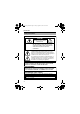
TK-C1530_EN.book Page 69 Friday, August 24, 2007 9:29 AM TK-C1531EG 126 U1-32 115 R5 4- 7,5 35 55 65 42 1/4-20UNC 30 T Specifications and appearance of this camera and related products are subject to change for improvements without notice.
TK-C1530_EN.