COLOR VIDEO CAMERA TK-WD310 INSTRUCTIONS (A) For Customer Use: Enter below the Serial No. which is located on the body. Retain this information for future reference. Model No. TK-WD310 Serial No.
These are general IMPORTANT SAFEGUARDS and certain items may not apply to all appliances. IMPORTANT SAFEGUARDS 1. Read all of these instructions. 2. Save these instructions for later use. 3. All warnings on the product and in the operating instructions should be adhered to. 4. Unplug this appliance system from the wall outlet before cleaning. Do not use liquid cleaners or aerosol cleaners. Use a damp cloth for cleaning. 5.
8. Slots and openings in the cabinet and the back or bottom are provided for ventilation, and to insure reliable operation of the appliance and to protect it from overheating, these openings must not be blocked or covered. The openings should never be blocked by placing the appliance on a bed, sofa, rug, or other similar surface. This appliance should never be placed near or over a radiator or heat register.
13. Follow all warnings and instructions marked on the appliance. 14. Do not overload wall outlets and extension cords as this can result in fire or electric shock. 15. Never push objects of any kind into this appliance through cabinet slots as they may touch dangerous voltage points or short out parts that could result in a fire or electric shock. Never spill liquid of any kind on the appliance. 16.
18. When replacement parts are required, be sure the service technician has used replacement parts specified by the manufacturer that have the same characteristics as the original part. Unauthorized substitutions may result in fire, electric shock, or other hazards. 19. Upon completion of any service or repairs to this appliance, ask the service technician to perform routine safety checks to determine that the appliance is in safe operating condition.
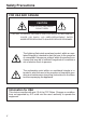
Safety Precautions FOR USA AND CANADA CAUTION RISK OF ELECTRIC SHOCK DO NOT OPEN CAUTION: TO REDUCE THE RISK OF ELECTRIC SHOCK. DO NOT REMOVE COVER (OR BACK). NO USER-SERVICEABLE PARTS INSIDE.REFER SERVICING TO QUALIFIED SERVICE PERSONNEL.
Due to design modifications, data given in this instruction book are subject to possible change without prior notice. WARNING: TO REDUCE THE RISK OF FIRE OR ELECTRIC SHOCK, DO NOT EXPOSE THIS APPLIANCE TO RAIN OR MOISTURE. AVERTISSEMENT: POUR EVITER LES RISQUES D’INCENDIE OU D’ELECTRO-CUTION, NE PAS EXPOSER L’APPAREIL A L’HUMIDITE OU A LA PLUIE. INFORMATION (FOR CANADA) RENSEIGNEMENT (POUR CANADA) This Class B digital apparatus complies with Canadian ICES-003.
INTRODUCTION Thank you for purchasing this product. (These instrustions are for TK-WD310U and TK-WD310E.) Before beginning to operate this unit, please read the instruction manual carefully in order to make sure that the best possible performance is obtained. Features 䡵 Backlight compensation over a wide area is realized by the 14-bit Wide Dynamic Range feature. The Wide Dynamic Range feature controls the exposure time using a maximum of 5 sampling timing for the image within a single screen.
EASY INSTALLATION The factory default settings are intended to give easy installation. Please attach a lens, a power supply, a video cable and mount the camera securely. You should now have good images. The additional information contained in this handbook is intended to give additional flexibility to more demanding installations. 䡲 Before starting an important recording, be sure to perform a test recording in order to confirm that a normal recording is possible.
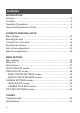
Contents INTRODUCTION Features ............................................................................................. 2 Contents ............................................................................................. 4 Operating Precautions ....................................................................... 5 Names and Operations of Parts ......................................................... 8 CONNECTION/INSTALLATION Basic System .........................................................
INTRODUCTION Operating Precautions ● To save energy, when it is not being used turn the system’s power off. ● This camera has been designed for indoor use. When you use it outdoors, be sure to use an appropriate housing. ● Do not install or use the camera in the following places. • In a place exposed to rain or moisture. • In a place with vapor or oil soot, for example in a kitchen. • When the ambient temperature rises above or falls below the acceptable range (from –10°C to 50°C).
INTRODUCTION Operating Precautions (continued) ● The white balance (ATW) of this device is optimally set for sunlight. Proper white balance may not be achieved for artificial lighting such as fluorescent lighting, etc. ● If you use this camera in locations where the camera is exposed to fluorescent light, a slow color change may occur. (White balance normal = 5,400 K, range is 2,500 K to 10,000 K.) ● AGC HIGH(×2) and up: in this mode, ATW white balance may be inaccurate.
● Blemishes: Small spots are normal, the camera contains compensation functions for blemishes above 120 mV (p-p) in value. Please contact your JVC authorised dealer for further information. ● For temperatures higher than the recommended temperature, the slow shutter may not work correctly.
INTRODUCTION Names and Operations of Parts [Front and Bottom] 2 1 4 5 3 7 6 1 Lens mount For use with CS mount lens. (C-mount lenses require a conversion ring.) 2 Backfocus adjustment ring Adjusting the back focus during lens installation. Please refer to “Back focus adjustment” on 墌 Page 22 for instructions on how to adjust the back focus.
3 [BF LOCK] Back focus locking screw (× 2: 2 mm) This serves to fix the back focus-adjusting ring. 4 Camera-mounting bracket The bracket has been attached on the bottom of the camera before shipment. It can also be attached on the top according to the circumstance. To re-attach the bracket use the threaded holes at the top, with the camera mounting bracket locking screws 7. 5 Camera-mounting screw hole (1/4 inch) Use this hole when mounting the camera onto a fixer, pan/tilt unit, and the like.
INTRODUCTION Names and Operations of Parts [Rear Panel] 8 SEE INSTRUCTION MANUAL DC12V AC24V 1 2 CLASS 2 ONLY (U TYPE) ISOLATED POWER ONLY (E TYPE) 9 A 0 POWER VIDEO OUT LL SET SELECTOR INT B C 8 [DC 12V, AC 24V] Power input terminals To input DC 12V or AC 24V power. 9 [VIDEO OUT] Video signal output connector This BNC connector outputs a composite video signal. Connect this to the video input connector of a video monitor, switcher, etc.
A [SET] button During normal screen display, pressing and holding this button for more than 2 seconds will display the MENU screen. (墌 Page 24) During MENU screen display, this button is pressed to display or enable the selected menu item. The input digit will change when entering the camera title. When selecting EXIT in the TOP MENU screen, pressing this button will return to the normal screen. B [SELECTOR] button Used when performing menu settings. This button is a multidirectional switch.
INTRODUCTION Names and Operations of Parts [Side Panel] COLOR VIDEO CAMERA IRIS VIDEO DC D E D [VIDEO/DC] Iris Selector Switch This should be set according to the type of lens if an automatic iris control lens is used. VIDEO : In case of lens with EE amp built-in. (墌 Page 20) DC : In case of lens without EE amp built-in. (墌 Page 14) (DC : At time of factory shipment) E [IRIS] Iris Terminal This is connected to an automatic iris control lens.
CONNECTION/INSTALLATION Basic System 䡵 System with up to 8 cameras H Av Pk L ALC LEVEL Camera 1 Power cable AC24V or DC12V COLOR VIDEO CAMERA Video signal cable H Av Pk L ALC LEVEL Camera 2 H ALC LEVEL Camera 8 Av Pk L AC24V or DC12V COLOR VIDEO CAMERA AC24V or DC12V COLOR VIDEO CAMERA • • • • • • Monitor DVR, etc. SR-L910 REC STOP/EJECT REVERSE REW PAUSE/ STILL REC CHECK OPERATE VIDEO CASSETTE RECORDER OPE.
CONNECTION/INSTALLATION Mounting the lens Mount the lens according to the procedures described below. Lens mount 1. (b) F (c) 3. 4. COLOR VIDEO CAMERA IRIS IRIS VIDEO DC VIDEO DC 1 3 2. 5.
1. Before mounting a lens, check whether it is CS-mount lens. Dimension (b) of the lens shown in the illustration must be as shown in the table below. If (b) exceeds the value in the table, it may damage the inside of the camera or correct mounting may be impossible; never use such lenses. The F mark indicates a focal point. Lens CS mount lens Flange back (c) 12.5mm Dimension (b) 5.5mm or less * When using the C-mount lens, use the conversion ring (CM46633001, MOUNT ADAPTOR). 2.
CONNECTION/INSTALLATION Connections on the back ● Turn off the power supply to all components before making connections. Power supply (DC 12 V or AC 24 V) SEE INSTRUCTION MANUAL DC12V AC24V 1 2 CLASS 2 ONLY (U TYPE) ISOLATED POWER ONLY (E TYPE) POWER VIDEO OUT LL SET SELECTOR INT Monitor 䡵 Video signal cable (BNC) Connect the coaxial cables (BNC) to the VIDEO OUT connector (BNC).
䡵 Power supply (DC 12 V or AC 24 V) Connect the DC 12 V or the AC 24 V power supply to the DC 12V/ AC 24V terminals. To prevent connection errors or a cable disconnection, we recommend the use of lug plates for the connections. The following table shows the connection distances and connection cables provided that 2-conductor VVF cables (vinyl-insulated vinyl sheath cables) are used. Maximum extension (reference) Conductor diameter 100 m 260 m 410 m 500 m 1.0φmm 1.6φmm 2.0φmm 2.
CONNECTION/INSTALLATION Mounting the camera Camera mounting screw hole Camera mounting bracket Rotation prevention hole When mounting the camera on a fixer, pan/tilt, etc., use the camera mounting screw hole located on the camera-mounting bracket. CAUTION: Use the screw with a length shorter than 7mm from a camera-mounting face. MAX. 7mm Furthermore, make use of the rotation prevention hole to prevent the camera from falling and securely mount the camera.
SEE INSTRUCTION MANUAL DC12V AC24V 1 2 6mm CLASS 2 ONLY (U TYPE) ISOLATED POWER ONLY (E TYPE) POWER VIDEO OUT LL SET 2mm SELECTOR INT M3 × 6 Fall Prevention • Exercise maximum caution when installing the unit to the wall or ceiling. You should not engage in the installation work yourself. Ask a professional to do the job, since the fall of the unit can result in injuries and accidents. • When installing the unit on a fixer, Pan/Tilt unit, etc.
CONNECTION/INSTALLATION Auto iris lens adjustment Connect the camera according to the connection method, turn it on, display an image on the monitor, and check the image. The white balance adjustment mode is selected. 墌 Page 33 “WHITE BALANCE” The camera has been factory-adjusted to the best position, but it may need to be adjusted according to the object conditions or combination of lenses. If the image is unnatural, adjust it as follows: (Also read the instruction manual of the lens.
• LEVEL adjustment Monitor screen Too bright Too dark LEVEL turning direction Counterclockwise (Toward L) Clockwise (Toward H) Memo ● If the sensitivity adjustment LEVEL is turned excessively to L, the sensitivity increases because of the AGC function of the camera, and the image looks grainy. ● At Low light levels, video iris lens may “Hunt”. Please adjust iris level on lens to minimise hunting.
CONNECTION/INSTALLATION Back focus adjustment Be sure to make back-focus adjustments when changing the lens mounting method or using a different lens. ● To make accurate back focus adjustments, carry out adjustments in a state where the lens iris is released. To open the lens iris, set MODE in the FOCUS ADJUST menu screen to ON. (墌 Page 27) ● The auto iris lens may operate under extremely bright conditions (7000lx or higher). In this case, use an ND filter to adjust the amount of light.
• With a fixed-focus lens If the focus can not be adjusted correctly by rotating the lens focus ring, adjust the back focus as follows. 1. Loosen the back focus locking screws by turning it counterclockwise ( ) with a Phillips screwdriver. (2 locations) 2. 3. 4. 5. Shoot a pattern closely. Turn the lens focus ring to ∞. Turn the back focus adjustment ring to focus at the best point. Tighten the back focus locking screws by turning it clockwise ( (2 locations) ).
MENU SETTING Menu settings SEE INSTRUCTION MANUAL DC12V AC24V 2 1 CLASS 2 ONLY (U TYPE) ISOLATED POWER ONLY (E TYPE) POWER VIDEO OUT SET SELECTOR INT LL SELECTOR button SET button Operation Cursor ——— ME N U — — — F OCU S A D J U S T . . V I D EO A D J US T.. C AM E R A S E T T I N G S . . F A C T OR Y S E T T I N GS . . EX I T 1. Press and hold the SET button for more than 2 seconds. ● The MENU screen appears. 2. Press Submenu (“..” displayed at the end.
— — — V I D E O A D J U ST — — — W D R M OD E A G C M OD E WH I T E B A L A N C E COL OR L E VE L E N HA NC E L E V E L EX I T MO D E 2 L OW A TW N O R MA L N O R MA L 4. Press the SELECTOR button in the vertical direction (6 or 7) and move the cursor (>) to the desired item. 5. Press the SELECTOR button in the — — — V I D E O A D J U ST — — — W D R M OD E A G C M OD E WH I T E B A L A N C E COL OR L E VE L E N HA NC E L E V E L EX I T MO D E 2 H I GH A TW N O R MA L N O R MA L ——— 6.
MENU SETTING Menu tree The menu screens are structured as shown below. Page 27 — — — FOCUS A D J U ST MOD E EX I T ——— OF F Page 28 ——— ME N U — — — FOCUS A D J US T.. V I DEO A D J US T.. C AM E R A S E T T I N G S . . F A C T OR Y S E T T I N GS . .
About menus FOCUS ADJUST ............ Used during focus adjustment of the auto iris lens. ( Page 27) VIDEO ADJUST ............. Sets the wide dynamic range, gain, color temperature, white balance, etc. ( Page 28) CAMERA SETTINGS ..... Sets the DC iris, camera title and vertical phase. ( Page 35) FACTORY SETTINGS ... Restores the menu settings to the factory settings. ( Page 39) FOCUS ADJUST screen MODE Default setting: OFF Used during focus adjustment of the auto iris lens.
MENU SETTING VIDEO ADJUST screen WDR MODE Default setting: MODE2 Setting of the wide dynamic range (WDR) is performed. CUSTOM : Manually adjusts the wide dynamic range. Pressing the SET button will display the WDR CUSTOM SETTINGS screen.
WDR CUSTOM SETTINGS screen The Wide Dynamic Range (WDR) is adjusted manually. Operation 1. Display — — — V I D E O A D J U ST — — — C U S T O M .. L OW A TW N O R MA L N O R MA L WD R MOD E A G C MOD E WH I T E B A L A N C E COL OR L E VE L E N HA NC E L E V E L EX I T the VIDEO ADJUST screen. ( Page 24) 2. Select WDR MODE and press the 3. — — W D R C U S TO M S E T T I N G S — — WD R B I A S – 36 WD R 4. 36 LI MIT E X P. B I A S WD R –8 0 25 –18 –4 BR I G HT 10 0 104 36 18 5.
MENU SETTING VIDEO ADJUST screen (continued) Item WDR BIAS WDR LIMIT EXP.
AGC MODE Default setting: LOW Sets the maximum gain of AGC (Auto Gain Control). You can set this device to maximum gain by the use of the slow shutter. Refer to the chart below and set according to the subject.
Memo ● When raising the gain, noise will appear in the screen for dark areas. ● When in a dark area and setting AGC MODE to HIGH (×2) and up: • Video may temporarily lock or noise may be noticeable. • The entire screen may temporarily change from a dark to a bright state. • When especially dark, depending on light intensity, the Wide Dynamic Range (WDR) feature will not function. (The WDR feature will function in normal light intensities.) • The right edge of the screen may temporarily jiggle.
MENU SETTING VIDEO ADJUST screen (continued) WHITE BALANCE Default setting: ATW The white balance adjustment mode is selected. White balance can be adjusted for lighting with color temperature in the range between 2,500K and 10,000K. ATW : The unit will be in the Auto Tracking White Balance mode. The white balance will be adjusted automatically according to the color temperature of the lighting.
MANUAL WHITE BALANCE screen If the entire screen appears to be reddish or bluish in color as the result of automatic white balance adjustment, manually adjust the white balance. — — — V I D E O A D J U ST — — — WD R MOD E A G C MOD E WH I T E B A L A N C E COL OR L E VE L E N HA NC E L E V E L EX I T MO D E 2 L OW MAN U AL.. N O R MA L N O R MA L Preparation Fill the entire screen with a white subject (such as paper, cloth, etc.). Operation 1. Display 2.
MENU SETTING VIDEO ADJUST screen (continued) COLOR LEVEL Default setting: NORMAL The color level of video signals is adjusted. ● To lighten colors: decrease the value. ● To darken colors: increase the value. [Setting range: -5 ~ NORMAL ~ 5] ENHANCE LEVEL Default setting: NORMAL The aperture control/contour level of the video signals is adjusted. ● Soften video: decrease the value. ● Sharpen video: increase the value.
5. When selecting EXIT and pressing the SET button, the screen will return to the CAMERA SETTINGS screen. Item DC GAIN Content Adjusts operating speed of the DC auto iris lens. Adjust according to the lens used. Increasing the value: the speed will increase [Setting range: 0 ~ 60 (default setting) ~ 255] * Depending on the lens, hunching may occur when setting this value too high. In this case, lower the value. Standard level (brightness) for controlling the DC auto iris operation is set.
MENU SETTING CAMERA SETTINGS screen (continued) CAMERA TITLE EDIT screen Up to 24 characters can be entered for the camera title. The entered camera title will appear on the bottom left of the screen when the CAMERA TITLE menu item is set to ON. Operation ——— CA M E R A SET T I NG S — — — L E NS A D J U S T .. C A ME R A T I T L E C A ME R A T I T L E E D I T OFF 1. Display the CAMERA SETTINGS screen. (墌 Page 24) 2. Press the SELECTOR button in V PHA SE 0 84 1 04 EX I T 3. 1st character 4. 5.
䡵 Allowed characters 8 direction (SELECTOR button) t direction Space Pressing the SELECTOR button in the t direction will select the character on the right and pressing in the 8 direction will select the character on the left. Pressing and holding the button will continuously change the character selected. Memo When CAMERA TITLE is set to ON, a background the width of 1 character is displayed, even when there is no camera title entered.
MENU SETTING FACTORY SETTINGS screen Returns set values to their factory settings. Operation ——— ME N U — — — F OC U S A D J U S T . . V I DEO AD J US T.. C AM E R A S E T T I N G S . . F AC T OR Y S E T T I NGS . . EX I T 1. Display 2. 3. Cursor — — — F A C T OR Y S ET T I N GS— — — CA N C E L CL E A R 4. the FACTORY SETTINGS screen. (墌 Page 24) Press the SELECTOR button in the vertical direction (6 or 7) and move the cursor (>) to CLEAR. Press the SET button.
OTHERS Troubleshooting Symptom The operation becomes unstable The auto iris will not operate There is noise in the screen or increase in residual images The colors of the screen are not natural White balance adjusted automatically/manually cannot be used The camera title will not appear The vertical phase cannot be adjusted using the V PHASE menu item 40 Remedy Drop in voltage of the power supply can be considered. Check the length and thickness of the power supply cable.
OTHERS Specifications Image pickup device Number of effective pixeis Synchronizaton method Scanning frequency : : : : 1/3 type WDR digital image device 380,000 pixels ((H) 720 × (V) 540) Internal,Line lock U Type (H) 15.734 kHz, (V) 59.94 Hz E type (H) 15.625 kHz, (V) 50.0 Hz Resolution : 480 TV lines (H) VIDEO OUT : Composite video signal 1 V(p-p), 75Ω (BNC) Video S/N ratio : 50 dB (AGC OFF) Minimum required illumination : 1.9 lx (50%, F1.2, AGC HIGH) 0.5 lx (50%, F1.2, AGC ULTRA(×16)) 0.95 lx (25%, F1.
TK-WD310 COLOR VIDEO CAMERA VICTOR COMPANY OF JAPAN, LIMITED is a registered trademark owned by VICTOR COMPANY OF JAPAN, LTD. is a registered trademark in Japan, the U.S.A., the U.K. and other countries.