COLOR VIDEO MONITOR TM-1051DG INSTRUCTIONS LCT1993-001B-H LCT1993-001A_Cover-ff.p65 1 06.1.
Thank you for purchasing this JVC Color Video Monitor. Before using it, read and follow all instructions carefully to take full advantage of the monitor’s capabilities. SAFETY PRECAUTIONS In order to prevent any fatal accidents caused by misoperation or mishandling of the monitor, be fully aware of all the following precautions. WARNINGS To prevent fire or shock hazard, do not expose this monitor to rain or moisture. Dangerous high voltages are present inside the unit.
POWER CONNECTION The power supply voltage rating of this product is AC 120 V (For U.S.A. and Canada only) and AC 220-240 V (For European countries or United Kingdom), the power cord attached conforms to the following power supply voltage and countries. Use only the power cord designated to ensure Safety and EMC regulations of each countries. Power cord Power supply voltage: Countries: AC 120 V U.S.A.
Controls and Features 7 Front Panel 1 2 3 4 1 Tally lamp 5 6 7 8 9 p 4 MENU control This lamp is controlled by the tally function of the MAKE/TRIGGER terminal. ☞ “How to Use the MAKE/TRIGGER Terminal” on pages 18 and 19 Displays or closes a menu screen. • You can set the lamp color to red or green.
UNDER SCAN button Reduces the screen size so that the whole screen is displayed. 6 SCREENS CHECK button Only the selected luminance signal or RGB element of a video signal is displayed. Each time you press this button, the screen changes in the following order: Normal screen = Monochrome screen = Red screen = Green screen = Blue screen = (back to the beginning) 7 MARKER button 7 About the status display Displays information of the current input selection and the monitor settings for about 3 seconds.
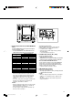
Controls and Features (cont.) 7 Rear Panel 3 1 2 4 5 1 Main power switch Turns the main power on and off. • I : on 䡬 : off NOTE: • You need to turn on the stand-by button on the front panel to turn on the monitor after turning on the main power switch. 2 AC inlet Power input connector. Connect the provided AC power cord to an AC outlet (120 V/220-240 V AC, 50 Hz/60 Hz). • Attach the provided Power Cord Holder to prevent accidental disconnection of the AC power cord.
6 6 Audio output terminals (E. AUDIO MONITOR OUT) Decodes EMBEDDED AUDIO signals and outputs them as analogue signals. • See the table below for the combinations of the audio channels from the CH1 or CH2 terminal.
Preparation 7Attaching the Power Cord Holder • The provided Power Cord Holder prevents accidental disconnection of the AC power cord from the AC inlet. • The Power Cord Holder consists of two parts; a case and a cover. 1. Attach the Power Cord Holder case to the AC inlet on the back of the monitor with 2 screws (provided). Caution: Use only the provided screws. 2. Attach the Power Cord Holder cover to the AC power cord. Close the cover until it clicks. 3.
Basic Menu Operations 7About the Menu Screens This monitor features MAIN MENU which contains the functions normally used and SET-UP MENU which contains the initial settings of the monitor. MAIN MENU Items Functions APERTURE CONTROL Compensates the frequency characteristics of the luminance signal of a video signal. sub menu SELECT Selects the positions and the contents of the sub-menu display.
Basic Menu Operations (cont.) 7Displaying the Menu Screens To display MAIN MENU Press the MENU control on the front panel. 7About “ sub menu” When “ sub menu” is displayed in the menu, only selected item in that menu can be displayed and adjusted. This allows you to make adjustments while looking at the actual screen. To display SET-UP MENU Press the CHROMA/PHASE button while moving the MENU control to . NOTES: • To exit the menu, press the MENU control several times.
How to Use MAIN MENU 7MAIN MENU Screens MAIN MENU Setting Items Move the MENU control to . ☞ page 10 ☞ page 12 Move the MENU control to / to adjust an item. About “ sub menu” and “reset,” ☞ page 10 ☞ page 12 * To go back to the previous menu, press the MENU control. NOTE: • Some items may not appear on the menu depending on the input or the input signal. Those items are not available to use.
How to Use MAIN MENU (cont.) MARKER Controls ON/OFF and other settings of the MARKER SELECT, ASPECT SELECT, and SAFETY MARKER functions included in the MARKER function. NOTES: • For the 4:3 screen ratio, only SAFETY MARKER and RSAFETY MARKER are displayed. • To set up non-“R-” items, press the MARKER button on the front panel. An external control system should not be operated at this time. • Using the external control, you can select either “R-” items or non-“R-” items to activate.
How to Use SET-UP MENU 7SET-UP MENU Screens SET-UP MENU Setting Items Move the MENU control to . ☞ page 17 Move the MENU control to / to adjust an item. About “ sub menu” and “reset,” ☞ page 10 * To go back to the previous menu, press the MENU control. NOTE: • Some items may not appear on the menu depending on the input or the input signal. Those items are not available to use. 13 EN04_LCT1993-001A-f.p65 13 06.1.
How to Use SET-UP MENU (cont.) 7Functions and Adjustment Range of Items FUNCTION SETTING Sets the control systems for the COLOR SYSTEM, synchronized signal, RUSH DELAY TIME, colors of the tally lamp, groups of the audio output modes, and MAKE/TRIGGER terminal. • Can be also used to check the amount of time that the monitor has been used. 7 COLOR SYSTEM Selects the color system. AUTO: Changes NTSC and PAL automatically. NTSC: Keeps the color system NTSC. PAL: Keeps the color system PAL.
PICTURE SUB ADJ. SIZE/POSI. ADJ. The standard value (“00”) of the picture adjustment is initially set at the factory. You can adjust the standard value as you want. 7 CONTRAST • –20 O 00 O +20 Adjusts the size and position of the picture. 7 H. SIZE Adjusts the horizontal screen size. • –20 O 00 O +20 (*) –: Reduces the screen size horizontally. +: Enlarges the screen size horizontally.
How to Use SET-UP MENU (cont.) DISTORTION ADJ. STATUS DISPLAY Compensates the picture distortion, tilt, and the color heterogeneity caused by the geomagnetic influence. 7 PARALLELOGRAM Compensates the parallelogram picture distortion. • –20 O 00 O +20 –: Moves the upper side of the picture to the right, and the lower side to the left. +: Moves the upper side of the picture to the left, and the lower side to the right. 7 TRAPEZOID Compensates the trapezoid picture distortion.
CONTROL LOCK Prohibits altering the monitor operations except turning the monitor on/off and deactivating this function. • ON/OFF NOTES: Control lock • When “CONTROL LOCK” is set to “ON,” “ on!” appears on the screen if you try to operate the monitor. • Operating the monitor by the external control is available if this function is activated.
How to Use the External Control 7About the External Control The Monitor has the MAKE/TRIGGER terminal, which allows you to control the monitor by the MAKE (make contact) or TRIG. (trigger) system selected in the function setting. MAKE (make contact) system: Controls the function by short-circuiting the corresponding pin terminal to the GND pin terminal, or disconnecting (opening) it. TRIG.
Functions controlled by the MAKE/TRIGGER Terminal Display INP. A INP. B INP. C INP. D CO. OFF MARKER ASPECT MA. SEL TALLY TA. SEL STATUS L.
Troubleshooting Solutions to common problems related to your monitor are described here. If none of the solutions presented here solve the problem, unplug the monitor and consult a JVC-authorized dealer or service center for assistance. Problems No power supply No picture with the power on Wrong color Unnatural picture Shaking picture Irregular color Points to be checked Measures (Remedy) Is the power plug loosened or disconnected? Firmly insert the power plug.
Points to be checked Problems Wrong picture position, wrong picture size Has the picture position, size, distortion, or tilt been changed? Measures (Remedy) Reference pages Adjust the picture size (H. SIZE, V. SIZE) or position (H. POSITION, V. POSITION) in “SIZE/ POSI. ADJ.” Adjust the picture distortion (PARALLELOGRAM, TRAPEZOID) or tilt (ROTATION) in “DISTORTION ADJ.” It may not be possible to expand the picture due to the selected input mode. In this case, adjustment is impossible.
Specifications Model Type Picture Tube Effective Screen Size Scanning Frequency Video Band Horizontal Resolution Input/Output Terminals Compliant Video Signal Format Environmental Conditions Power Requirements Power Consumption Dimensions Weight Accessory TM-1051DG Color Video Monitor 10" measured diagonally Width: 176.9 mm (6 15/16") Height: 137.6 mm (5 3/8") Diagonal: 224.
7Dimensions Unit : mm (inch) Front View Side View 1.5 (1/16") 220 (8 3/4") 140 (5 5/8")* 222 (8 3/4") 183 (7 1/4")* 360.3 (14 1/4") 347.8 (13 3/4") 307.8 (12 1/8") 164 (6 1/2") 7 (3/8") 63.5 (2 1/2") 222 (8 3/4") 7 (3/8") Asterisks (*) are used to indicate front panel dimensions. 23 EN04_LCT1993-001A-f.p65 23 06.1.
TM-1051DG COLOR VIDEO MONITOR © 2006 Victor Company of Japan, Limited EN04_LCT1993-001A-f.p65 24 0106MKH-MW-VP 06.1.