ENGLISH LCD DISPLAY MONITOR TM-15L1D 01_TM-15L1D-EN2indd.indd 1 INSTRUCTIONS 06.11.
Safety Precautions IMPORTANT SAFEGUARDS Electrical energy can perform many useful functions. This unit has been engineered and manufactured to assure your personal safety. But IMPROPER USE CAN RESULT IN POTENTIAL ELECTRICAL SHOCK OR FIRE HAZARD. In order not to defeat the safeguards incorporated into this product, observe the following basic rules for its installation, use, and service. Please read these “IMPORTANT SAFEGUARDS” carefully before use.
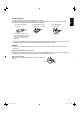
For U.S.A. and Canada: AC 120 V For European and Asian countries: AC 220 – 240 V ENGLISH POWER CONNECTION The power supply voltage rating of this product is AC 100 – 240 V. The power cord attached conforms to the following power supply voltage and countries. Use only the power cord designated to ensure safety and EMC regulations of each countries. For United Kingdom: AC 220 – 240 V • This product is equipped with a grounding-type plug to satisfy FCC rule.
Safety Precautions (cont.) • Make enough room for inserting or removing the power plug. Place the product as close to the outlet as possible. The main power supply for the product is controlled by inserting or removing the power plug. • When the product is left unattended and unused for long periods of time, unplug it from the wall outlet and disconnect the cables.
ENGLISH • Never push objects of any kind into this product through openings as they may touch dangerous voltage points or short out parts that could result in a fire or electric shock. • Never spill liquid of any kind on the product. Under the following conditions, 1. Turn off the power. 2. Unplug this product from the wall outlet. 3. Refer service to qualified service personnel. a) When the product emits smoke or unusual smell.
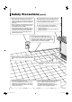
Safety Precautions (cont.) Maintenance Unplug this product from the wall outlet before cleaning. Screen To avoid irreparable change in appearance of the screen such as uneven color, discoloration, scratches, be careful about the following: • Do not paste or stick anything with any glues or adhesive tapes. • Do not write anything on the screen. • Do not strike the screen with a hard object. • Avoid condensation on the screen. • Do not wipe the screen with solvent such as alcohol, thinner, or benzine.
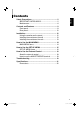
Contents ENGLISH Safety Precautions ........................................................ 2 IMPORTANT SAFEGUARDS ................................... 2 Maintenance ............................................................. 6 Controls and Features .................................................. 8 Front panel ............................................................... 8 Rear panel .............................................................. 10 Installation ......................................
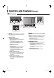
Controls and Features 7 Front panel Tally lamp Controlled by the MAKE/TRIGGER terminal. (☞ “TALLY SELECT” on page 17, “How to Use the External Control” on page 18) 1 1 Speaker (Monaural) 2 3 4 56 5 Volume control button*2 Outputs the audio signal of the selected input. While the menu is not displayed, adjust the volume level (00 to 50) by pushing the button left or right. 2 CHROMA/PHASE button*1 Activates the Chroma (picture color density) adjustment mode or the Phase (picture hue) adjustment mode.
ENGLISH 8 8 ASPECT button/lamp Changes the aspect ratio of the picture from 4:3 to 16:9. • When “16:9” is selected, the lamp lights up. • To return to 4:3, press the button again. • Use this function when the picture of 16:9 aspect ratio is squeezed into 4:3 format signal. NOTE: • When displaying the picture in the 1:1 mode (☞ “ 7 SCAN SIZE button/lamp” on page 8), this function does not work. In this case, “NO EFFECT” is displayed for about 5 seconds (the lamp lights up).
Controls and Features (cont.) 7 Rear panel a b e f cd 3 4 2 1 AC inlet Power input connector. Connect the provided AC power cord to an AC outlet (AC 120 V/AC 220 – 240 V, 50 Hz/60 Hz). 2 VIDEO terminals a VIDEO 1 terminals (BNC) Input (IN) and output (OUT) terminals for the composite signals. • The IN and OUT terminals are bridgeconnected (auto termination). • Use the AUDIO 1 terminal for the audio connection. b VIDEO 2 terminals (BNC) Input (IN) and output (OUT) terminals for the composite signals.
ENGLISH g hi j k 5 6 5 SDI terminals g AUDIO 1 terminal (pin jack) Input terminal for the analog audio signals. • Use the SDI 1 terminal for the video connection. h AUDIO 2 terminal (pin jack) Input terminal for the analog audio signals. • Use the SDI 2 terminal for the video connection. i SDI 1 terminal (BNC) Input terminal for the SD SDI signals. • Use the AUDIO 1 terminal for the audio connection. j SDI 2 terminal (BNC) Input terminal for the SD SDI signals.
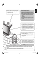
Installation NOTE: • Do not rest your arm on the monitor or lean against the monitor. • Do not hold the LCD panel when installing the monitor. • Make sure to install the monitor securely to prevent the monitor from falling over, which causes damage to the monitor or injury. 7 Using the monitor on the stand You can place the monitor in the following two ways when using the monitor on the supplied stand. You can tilt the monitor upward or downward within the range of about 20° in each direction.
ENGLISH 7 Installing the monitor on the wall Use a commercial wall mounting unit compliant with the VESA standard (100 mm x 100 mm). NOTE: • Detach the stand first. (☞ page 12) • Ask your dealer to install. VESA mounting holes (See page 22 for the specifications of the mounting holes.) 7 Installing the monitor on the rack Use a JVC’s RACK MOUNT ADAPTER (RK-C157L1G; not supplied). NOTE: • Detach the stand first. (☞ page 12) • Ask your dealer to install. 13 03_TM-15L1D-EN2.indd 13 06.11.
How to Use the MAIN MENU The MAIN MENU contains the functions for daily use. MAIN MENU 1 Select 2 Adjust 1 Select “all reset” Operation guide Shows the buttons for each operation. Perform “all reset” 2 Next 7 To exit the menu: Cancel NOTE: • The menu automatically disappears in about 30 seconds after the last menu operation. • Some items may not appear on the menu. Those items are not available for the current input or the current input signal.
How to Use the SET-UP MENU 1 Select ENGLISH The SET-UP MENU contains the initial settings of the monitor. SET-UP MENU 7 PICTURE SUB ADJ. 1 Select 2 Adjust Press CHROMA/ PHASE while pressing MENU. 2 Next 1 Select “reset” Operation guide Shows the buttons for each operation. 2 Perform “reset” 7 COLOR TEMP. 1 Select 1 Select 7 To exit the menu: 2 Adjust 2 Adjust Next (When selecting “USER1” or “USER2” in 2) 7 SIZE/POSI. ADJ. (Only when “SCAN SIZE” is “USER”) 1 Select 1 Select 2 Adjust 2 Next Ex.
How to Use the SET-UP MENU (cont.) 7 SET-UP MENU items PICTURE SUB ADJ. Sets the standard level for the picture adjustments by using the CHROMA/PHASE and CONTRAST/BRIGHT buttons on the front panel. CONTRAST* Adjusts the standard level for contrast adjustment. –20 - 00 - +20 BRIGHT* Adjusts the standard level for brightness adjustment. –20 - 00 - +20 CHROMA* Adjusts the standard level for chroma adjustment. –20 - 00 - +20 PHASE* Adjusts the standard level for phase adjustment.
ENGLISH NO SYNC FUNCTION Selects the screen status when no signal is being input. NO SYNC DISPLAY Sets the screen status when no signal is being input. OFF, SUSPEND (suspend mode), GRAY (gray screen) DELAY TIME Sets the period until the screen status changes after signals stop coming in. 5, 20, 60 (seconds, approx.) TALLY SELECT Selects the tally lamp color. Setting value: GREEN, RED NOTE: • To control the tally lamp, use the MAKE/TRIGGER terminal.
How to Use the External Control 7 About the external control The monitor has the MAKE/TRIGGER terminal, which allows you to control the monitor by the MAKE (make contact) or TRIG. (trigger) system. MAKE (make contact) system: Controls the function by short-circuiting the corresponding pin terminal to the GND pin terminal, or disconnecting (opening) it. TRIG. (trigger) system: Controls the function by inputting the pulse signal instantaneously to the corresponding pin terminal. * Select “MAKE” or “TRIG.
Troubleshooting Problems Points to be checked Measures (Remedy) Reference pages No power supply Is the power plug loosened or disconnected? Firmly insert the power plug. No picture with the power on Is the signal cable disconnected? Connect the signal cable firmly. Is the power of the connected component on? Is the signal being output from the connected component? Turn on the power of the connected component and set the output correctly.
Troubleshooting Problems Wrong picture position, wrong picture size (cont.) Points to be checked Has the picture position or size been changed? Is the input signal adapted to the monitor’s specification? Measures (Remedy) Reference pages Adjust the picture size (H. SIZE/V. SIZE) or position (H. POSI./V. POSI.) in “SIZE/POSI. ADJ. (USER)” in the SET-UP MENU. 16 For some signals, the picture cannot be displayed fully in the effective screen area. There is no sure method to solve this problem.
Model TM-15L1D Type LCD Display Monitor LCD panel 15”, active matrix TFT Effective Screen Size Width: Height: Number of Pixels Displayed 1024 x 768 Horizontal/vertical Frequency H: V: Input/Output Terminals Composite video: VIDEO 1 Video SDI 1 SDI 2 SDI SW. OUT 304.1 mm (11 15/16”) 228.1 mm (8 15/16”) 15.625 kHz/15.734 kHz 50 Hz/59.94 Hz VIDEO 2 COMPONENT ENGLISH Specifications 1 line, BNC connector x 2, 1 V(p-p), 75 Ω * The input (IN) and output (OUT) terminals are bridgeconnected.
Specifications (cont.) 7 Dimensions Unit : mm (inch) Front View Side View Rear View (without the stand) 70.5 (2 7/8) 135 (5 3/8) 100 330.6 (13 1/8)* / 295.6 (11 3/4)** 291 (11 1/2) 280 (11 1/8) 100 28.5 (1 1/8) 342 (13 1/2) VESA mounting holes (Size: M4, depth: 10 mm) 184 (7 1/4) * at the higher position ** at the lower position Specification of the COMPONENT terminal (mini D-sub 15-pin) Pin No. Input signal Pin No.