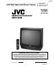
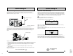
TM-2001U TM-2701SU OPERATING INSTRUCTIONS [ TM-2001U ] TM-2701SU For models: TM-2001U TM-2701SU COLOR MONITOR/RECEVER USER'S GUIDE Illustration of TM-2001U and RM-C307 IMPORTANT NOTE TO THE CUSTOMER In the space below, enter the model number and serial number of your television (located at the rear of the television cabinet). Staple your sales receipt or invoice to the inside cover of this guide. Keep this user's guide in a convenient place for future reference.
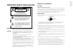
CAUTION RISK OF ELECTRIC SHOCK DO NOT OPEN CAUTION:To reduce the risk of electric shock. Do not remove cover (or back). No user serviceable parts inside. Refer servicing to qualified service personnel. The lightning flash with arrowhead symbol, within an equilateral triangle is intended to alert the user to the presence of uninsulated “dangerous voltage” within the product’s enclosure that may be of sufficient magnitude to constitute a risk of electric shock to persons.
7 An outside antenna system should not be located in the vicinity of overhead power lines or other electric light or power circuits, or where it can fall into such power lines or circuits. When installing an outside antenna system, extreme care should be taken to keep from touching such power lines or circuits as contact with them might be fatal.
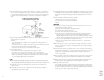
Thank you for your purchase of a JVC Color Television. Before you begin setting up your new television, please check to make sure you have all of the following items.
Quick Setup 3 Quick Setup 2 Step Two - Making Basic Connections Step Three - Auto Tuner Setup Next you will need to connect your television to an antenna or cable system. The most basic antenna/cable connection is shown below. For more detailed connections, such as ones where a cable box is required, see pages 11 and 12. JVC’s onscreen menu system lets you set your television up to meet your own personal viewing preferences. The menu screens and their features are discussed in detail in this book.
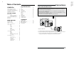
Connections Quick Setup Guide . . . . . . . . . . . . 7 BUTTON FUNCTIONS CONNECTIONS Menu. . . . . . . . . . . . Exit. . . . . . . . . . . . . Display . . . . . . . . . . . Video Status . . . . . . . . Sleep Timer . . . . . . . . . Hyper Surround . . . . . . Muting . . . . . . . . . . . 100+ . . . . . . . . . . . . Return+. . . . . . . . . . . Input. . . . . . . . . . . . VCR Buttons . . . . . . . . DVD Buttons . . . . . . . . TV/CATV Switch . . . . . . VCR/DVD Switch . . . . . .
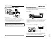
Connections Connections Cable and VCR Connections - Continued Stereo VCR/DVD Connections Diagram #2 You can use the connection shown below for high-quality stereo sound from your HiFi VCR. You can also use this diagram to connect your television to a DVDplayer.
Remote Control Connecting to a Camcorder You may connect a camcorder to your television by using the front Input Jacks (Input 2). You may also connect a game console or other equipment using these jacks. Camcorders may also be connected to the television’s rear input jacks. Remote Control Basics • Before you can operate the remote control, you must first install TV CATV VCR DVD POWER INPUT 2 VIDEO L MONO AUDIO R INPUT the batteries (included).
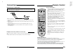
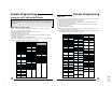
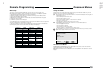
Remote Programming Remote Programming Setting the CATV, VCR and DVD Codes You can program your remote to operate your cable box, satellite receiver, VCR or DVD player by using the instructions and codes listed below. If the equipment does not respond to any of the codes listed below or to the code search function, use the remote control supplied by the manufacturer.
Onscreen Menus DVD setup Using the Guide The remote control is programmed with DVD codes for power on, power off, play, stop, fast-forward, rewind, previous chapter, next chapter, tray open/close, and still/pause operation. Certain symbols are used throughout this guide to help you learn about the features of your new television. The ones you will see most frequently are: 1) 2) 3) 4) 5) 6) ❷ Up and Down arrows mean press the CHANNEL UP or CHANNEL DOWN buttons.
Initial Setup Initial Setup Auto Tuner Setup Channel Summary If you have already run the Auto Tuner as part of the quick setup earlier in this guide, please skip ahead to “Channel Summary” to continue setting up your television. Channel Summary allows you to customize the line-up of channels received by your TV. You can add or delete channels from the line-up or prevent any unauthorized viewers from watching any or all 181 channels.
V-Chip Your TV is equipped with V-Chip technology which enables TV Parental Guidelines (for United States and Canada) and Movie (MPAA) Guideline controls. V-Chip technology allows you to program your TV to receive, or not to receive, programs based on content according to the guidelines. Programs which exceed the ratings limits you set will be blocked. When a viewer attempts to watch a blocked channel, this message appears: THIS PROGRAMMING EXCEEDS YOUR RATING LIMITS.
V-Chip V-Chip Setting US V-Chip Ratings To access Rating information about a certain program, press the V-CHIP button while viewing that program.
V-Chip Movie Ratings Canadian V-Chip Ratings ❒ NR - Not Rated. This is a film which has no rating. In many cases these films were imported from countries which do not use the MPAA ratings system. Other NR films may be from amateur producers who didn’t intend to have their film widely released. NR (Not Rated) Programming may contain all types of programming including children's programming, foreign programs, or adult material. ❒ E - Exempt.
V-Chip V-Chip Unrated Programs Set Lock Code Notes About Unrated Programs: Unrated programming refers to any programming which does not contain a rating signal. Programming on television stations which do not broadcast rating signals will be placed in the “Unrated Programming" category.
Tint Noise Muting Tint allows you to adjust the levels of red and green in your TV picture. Press the MENU button ❷ ❿ ➛ ❷ To TINT To increase the levels of green To increase the levels of red To move to the next setting The color function lets you make all the colors in the TV picture appear either more vivid or subtle. Press the MENU button ❿ ➛ ❷ This feature inserts a blank blue screen over channels which are not broadcasting or are too weak to be received clearly.
Sound Settings MTS (Multi-Channel Television Sound) Bass You can increase or decrease the level of low-frequency sound in the TV’s audio with the Bass adjustment. Press the MENU button ❷ ❿ ➛ ❷ To increase the bass To decrease the bass Press the MENU button ❷ Press the MENU button ❷ ➛❿ To move to the next setting Treble ❿ ➛ MTS technology allows several audio signals to be broadcast at once, giving you a choice in what you wish to hear with a TV program.
General Items Auto Clock Set Manual Clock Set Before you use any of your TV’s timer functions, you must first set the clock. You may precisely set your clock using the XDS time signal broadcast by most Public Broadcasting stations. To set the clock using the XDS signal: To set your clock manually (without using the XDS signal), choose MANUAL from the Set Clock menu and follow the steps below.
General Items General Items On/Off Timer Closed Caption The On/Off timer lets you program your television to turn itself on or off. You can use it as an alarm to wake up, to help you remember important programs, or as a decoy when you're not home. Use this function to display the Closed Captioning text onscreen (when included in a broadcast).
Button Functions Menu Video Status The MENU button allows you to access JVC’s onscreen menu system. Press MENU to activate the onscreen menu system. The VIDEO STATUS button gives you a choice of three TV picture display settings, including a display of your own preferences. • See individual topics (like “Set Video Status”) for specific information on using menus. Standard - Resets the picture display to the factory settings.
Button Functions Button Functions 100+ Button VCR Buttons Use the 100+ button to directly access channels above Channel 99. For example to move to channel 124, press100+, 2 (two), 4 (four). You can use this remote control to operate the basic functions of your VCR. These functions include: play, record, rewind, fast-forward, stop, pause, channel scan, TV / VCR, power on, and power off. Move the selector switch to VCR to operate.
PROBLEMS TM-2001U TM-2701SU 22 Troubleshooting Search Codes CHECK There is no power • See if the power cord became unplugged. • Check for a blown fuse or circuit breaker or a power outage. There is no picture or sound • The antenna could be disconnected. • The input mode could be set improperly. See page 40. • The tuner (Auto Tuner Setup) could be set improperly. See page 20. • The TV station may be having difficulties. Check to see if other stations are working.
BNC connector box Bridge-connection BNC connection box installation The IN and OUT terminals are bridge-connected. (When no cable is connected to the OUT terminal, the input signal is automatically terminated.) 1 IN IN OUT OUT 3 VIDEO Illustration of TM-2701SU IN L BNC Connector box AUDIO R OUT Video 2 VIDEO EQUIPMENT IDEO L/ MONO 1 Slide the claps on the BNC connector box into the slots at the back of the television until it clicks into position.
TM-2001U TM-2701SU 24 Specifications MODEL TM-2001U TM-2701SU Reception Format NTSC, BTSC System (Multi-Channel Sound) Reception Range VHF 2 to 13, UHF 14 to 69 Sub Mid, Mid, Super, Hyper and Ultra bands (181 channel frequency synthesizer system) Power Source Power Consumption Screen Size Audio Output AC 120V, 60Hz 87W / 1.4A 113W / 1.8A 20 inch / 51 cm measured diagonally full square 27 inch / 68 cm measured diagonally full square 1W + 1W 1.2W + 1.